

Vulcan-Hart VCCB25, VCCB30, VCCB36, VCCB47, VCCB60 Service Manual
...
SERVICE MANUAL
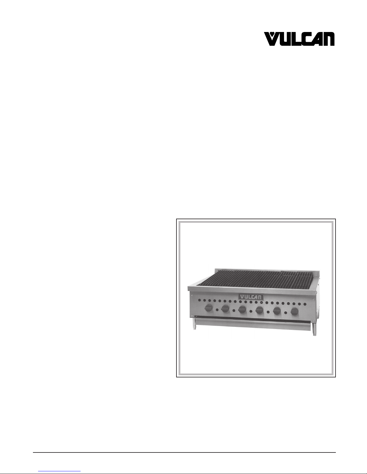
VCCB COUNTERTOP CHAR-BROILER
MODEL NO.
VCCB25 ML-114540
VCCB30 ML-114541
VCCB36 ML-114542
VCCB47 ML-114543
VCCB60 ML-114544
VCCB72 ML-114545
VCCB84 ML-114546
MODEL VCCB36
VULCAN-HART COMPANY, P.O. BOX 696, LOUISVILLE, KY 40201-0696, TEL. (502) 778-2791
FORM 30952 (1-96)
IMPORTANT FOR YOUR SAFETY
THIS MANUAL HAS BEEN PREPARED FOR PERSONNEL QUALIFIED TO INSTALL GAS
EQUIPMENT, WHO SHOULD PERFORM THE INITIAL FIELD START-UP AND
ADJUSTMENTS OF THE EQUIPMENT COVERED BY THIS MANUAL.
POST IN A PROMINENT LOCATION THE INSTRUCTIONS TO BE FOLLOWED IN THE
EVENT THE SMELL OF GAS IS DETECTED. THIS INFORMATION CAN BE OBTAINED
FROM THE LOCAL GAS SUPPLIER.
IMPORTANT
IN THE EVENT A GAS ODOR IS DETECTED, SHUT
DOWN UNITS AT MAIN SHUT-OFF VALVE AND
CONTACT THE LOCAL GAS COMPANY OR GAS
SUPPLIER FOR SERVICE.
FOR YOUR SAFETY
DO NOT STORE OR USE GASOLINE OR OTHER
FLAMMABLE VAPORS OR LIQUIDS IN THE
VICINITY OF THIS OR ANY OTHER APPLIANCE.
WARNING
IMPROPER INSTALLATION, ADJUSTMENT,
ALTERATION, SERVICE OR MAINTENANCE CAN
CAUSE PROPERTY DAMAGE, INJURY OR DEATH.
READ THE INSTALLATION, OPERATING AND
MAINTENANCE INSTRUCTIONS THOROUGHLY
BEFORE INSTALLING OR SERVICING THIS
EQUIPMENT.
IN THE EVENT OF A POWER FAILURE, DO NOT
ATTEMPT TO OPERATE THIS DEVICE.
— 2 —

TABLE OF CONTENTS
Important safety information page 2
Codes and standards information page 3
Clearance information page 3
Manual use information page 3
Data plate information page 3
Tools required for servicing page 3
General appliance information page 4
Section l Service Checks and Adjustments page 5-8
Section ll Removal of Service Parts page 9-18
Section lll Troubleshooting page 19
CODES AND STANDARDS
Vulcan-Hart Charbroilers are to be installed in accordance with state and local codes, or in the absence of local
codes, with the National Fuel Gas Code, ANSI-Z223.1 (latest edition), available from the American Gas
Association, Inc., 1515 Wilson Blvd., Arlington, Va. 22209 and with ANSI-NFPA Standard #96 (latest edition),
Vapor Removal From Cooking Equipment, available from the National Fire Protection Association, Batterymarch
Park, Quincy, MA 02269.
CLEARANCES
COMBUSTIBLE NON-COMBUSTIBLE
CONSTRUCTION CONSTRUCTION
BACK Above Grid Level 12" 0"
Below Grid Level 3" 0"
SIDES Above Grid Level 9" 0"
Below Grid Level 3" 0"
HOW TO USE THIS MANUAL
This manual is dedicated to the servicing of the Vulcan-Hart Co. VCCB Countertop Char-Broiler.
The manual is divided into 3 sections, CHECKS AND ADJUSTMENTS, REMOVAL OF SERVICE PARTS AND
TROUBLESHOOTING. For additional technical assistance refer to the service assistance number on the front
cover of this manual. Refer to parts manual to identify service replacement parts.
DATA PLATE
The data plate which identifies the appliance model no., device no., serial no., gas specification, clearances and
agency approvals is located on the lower right body side of the appliance.
TOOLS REQUIRED
Tools required to preform the service operations covered in this manual.
1. Standard set of hand tools.
2. 1/2" Deep throat socket.
3. Offset flat blade screwdriver.
2. Temperature tester (thermocouple or digital pyrometer).
4. Gas test kit.
— 3 —

GENERAL APPLIANCE INFORMATION
VCCB25 is a 25" wide Char-Broiler with 4 burners rated at 14,500 BTU's ea.
VCCB30 is a 30" wide Char-Broiler with 5 burners rated at 14,500 BTU's ea.
VCCE36 is a 36" wide Char-Broiler with 6 burners rated at 14,500 BTU's ea.
VCCB47 is a 47" wide Char-Broiler with 8 burners rated at 14,500 BTU's ea.
VCCB60 is a 60" wide Char-Broiler with 11 burners rated at 14,500 BTU's ea.
VCCB72 is a 72" wide Char-Broiler with 13 burners rated at 14,500 BTU's ea.
VCCB84 is a 84" wide Char-Broiler with 16 burners rated at 14,500 BTU's ea.
— 4 —

SECTION I
SERVICE CHECKS AND ADJUSTMENTS
WARNING: SHUT OFF GAS BEFORE SERVICING
VENTILATION CHECKS
Insure that adequate ventilation has been provided in accordance to all codes as stated on page 3 of this manual.
The vent for this appliance should be checked for restrictions every 6 months.
GAS SUPPLY CHECKS
If the gas supply piping is to be tested at a test pressure in excess of 1/2 psig(3.45Kpa), the appliance and its
individual shut-off valve must be disconnected from the supply line. If the gas supply piping system is to be tested
at a pressure equal to or less than 1/2 psig(3.45Kpa), the individual shut-off valve must be closed during testing.
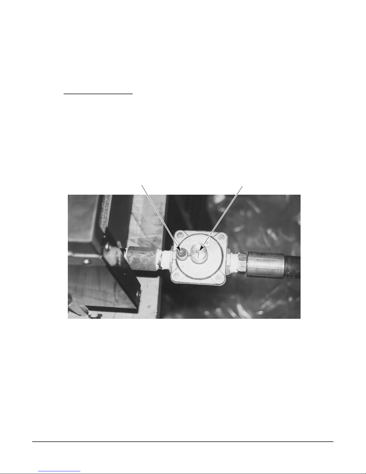
REGULATOR VENT CHECK
1. With a screwdriver pry the plastic vent plug from the top of the regulator. (See Fig. 1)
2. Check vent for clogging of the breather vent screen. If screen is obstructed, clear the obstruction.
STORE LINE GAS PRESSURE CHECK
1. Turn main gas line off.
2. Tap the store line ahead of the pressure regulator if a gas pressure tap and plug have not been supplied.
3. Install a single pilot valve fitting or similar device that will allow a gas pressure gauge to be connected to
the store line.
4. Connect the gas pressure gauge to the tapped valve device.
5. Turn the store main gas on.
6. Turn the unit gas on.
7. Take the store pressure reading. Store pressure should be at least 6" W.C. for natural gas and 11" W.C.
for propane gas.
8. If store pressure is not correct advise owner that the gas line pressure must be serviced for proper gas flow
before appliance service can be preformed.
9. If store pressure is correct, continue checking by performing the appliance gas line check.
APPLIANCE GAS LINE CHECK
1. Turn appliance gas off.
2. Remove the burner knobs.
3. With a phillips head screwdriver remove (4) screws securing the front cover to the broiler.
4. From the front right side of the appliance follow the gas pipe to the gas line pressure tap.
5. Connect the gas meter to the line pressure tap.
6. Reinstall the burner knob handle and turn the appliance gas on.
7. Check the appliance pressure. Reading should be 5" W.C. for natural gas and 10" W.C. for propane gas.
PILOT CHECK
1. Follow steps 1-3 under Removal of Pilot Tubing.
2. With a 7/16" wrench remove the pilot from the pilot tube.
3. Examine the pilot and the tube for blockage.
4. If blockage is found, remove it using air or water pressure.
5. If blockage cannot be removed, replace the pilot.
6. Reinstall or replace pilot by reversing steps 1-2 above.
— 5 —
BURNER NOZZLE ORIFICE CHECK
Perform this procedure only after the pilot has been checked and the pilot valve has been adjusted.
1. Follow steps 1-2 under Removal of Front Cover.
2. Follow steps 1-2 under Removal of Top Grates.
3. Follow steps 1-5 under Removal of Radiants.
4. Follow steps 3-5 under Removal of Burner/Deflector Assembly.
5. With a
1/2" deep throat socket remove the burner nozzle from the burner valve. (See Fig. 15)
4. Inspect the nozzle for blockage.
5. If blockage is found, loosen the hood compression nut and remove the hood.
6. Clear blockage by blowing compressed air or water through the hood orifice opening.
7. Reinstall or replace the burner nozzle by reversing steps 1-5 above.
REGULATOR ADJUSTMENT
1. Follow steps 1-2 under Regulator Vent Check.
2. Follow steps 1-9 under Store line Gas Pressure Check and steps 1-7 under Appliance Gas Line Check.
3. If store pressure checks out but the appliance pressure is not correct, with a flat blade screwdriver remove
the regulator adjustment closure cap. (Fig. 1)
VENT PLUG
Fig. 1
ADJUSTMENT CAP
4. With a flat blade screwdriver, while still connected to the pressure gauge, rotate the regulator adjustment
screw clockwise to increase pressure and counterclockwise to decrease pressure. Appliance pressure
should be 5" W.C. for natural gas and 10" W.C. for propane gas. Adjust the regulator to obtain the required
reading.
PILOT VALVE ADJUSTMENT
1. Follow lighting instructions if pilot is not already lit.
2. Follow steps 1-2 under Removal of Front Cover.
3. Remove the top grates so that the pilot flame can be clearly seen.
— 6 —
 Loading...