

Page 1

INSTALLATION &
OPERATION MANUAL
HEAVY DUTY ELECTRIC
SALAMANDER BROILERS
MODELS VB73, VB73R & ESB36
VB73 Broiler
For additional information on Vulcan-Hart or to locate an authorized parts
and service provider in your area, visit our website at www.vulcanhart.com
VULCAN-HART
DIVISION OF ITW FOOD EQUIPMENT GROUP, LLC
F-33214 Rev. A (01-04) www.vulcanhart.com
P.O. BOX 696, LOUISVILLE, KY 40201-0696
TEL. (502) 778-2791
Page 2
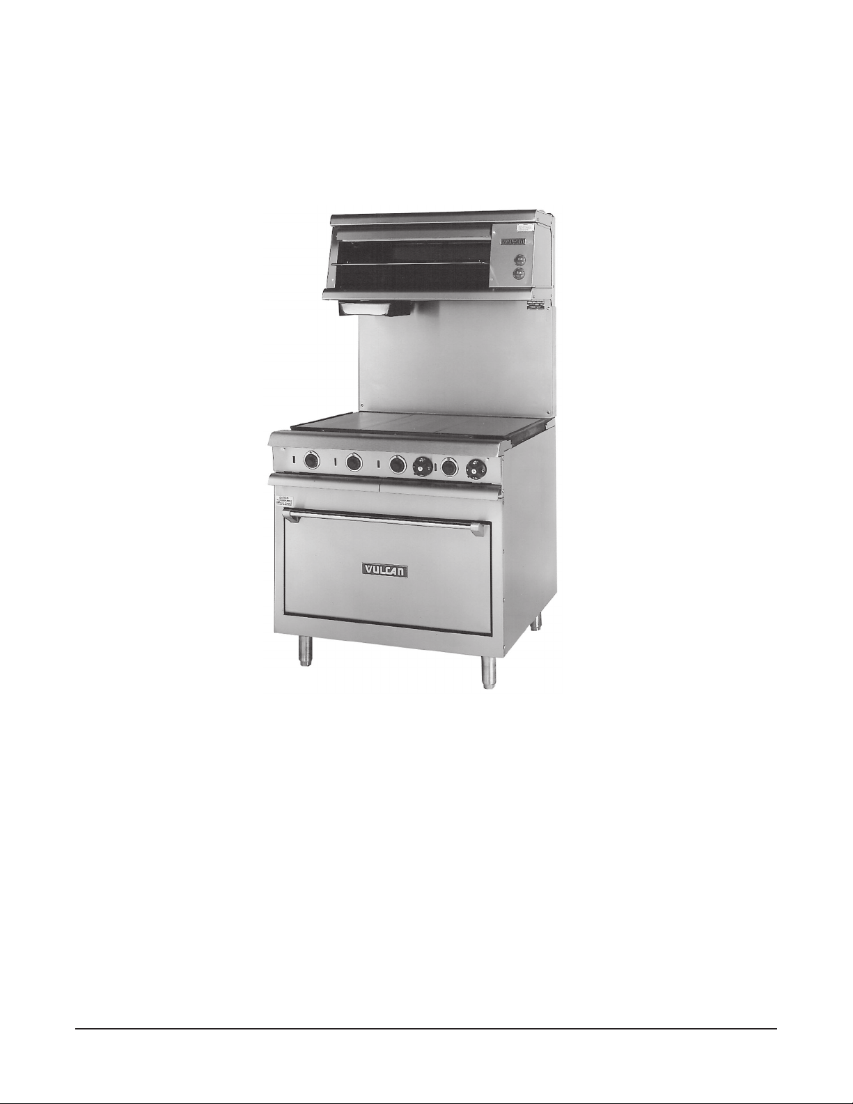
VB73 SALAMANDER BROILER MOUNTED OVER VR2 RANGE
— 2 —
Page 3

TABLE OF CONTENTS
GENERAL . . . . . . . . . . . . . . . . . . . . . . . . . . . . . . . . . . . . . . . . . . . . . . . . . . . . . . . . . . . . . . . . . . . . . . 4
INSTALLATION . . . . . . . . . . . . . . . . . . . . . . . . . . . . . . . . . . . . . . . . . . . . . . . . . . . . . . . . . . . . . . . . . . 4
Unpacking . . . . . . . . . . . . . . . . . . . . . . . . . . . . . . . . . . . . . . . . . . . . . . . . . . . . . . . . . . . . . . . . . 4
Installation Codes and Standards . . . . . . . . . . . . . . . . . . . . . . . . . . . . . . . . . . . . . . . . . . . . . . 4
Location . . . . . . . . . . . . . . . . . . . . . . . . . . . . . . . . . . . . . . . . . . . . . . . . . . . . . . . . . . . . . . . . . . 5
Assembly . . . . . . . . . . . . . . . . . . . . . . . . . . . . . . . . . . . . . . . . . . . . . . . . . . . . . . . . . . . . . . . . . 5
Electrical Connections . . . . . . . . . . . . . . . . . . . . . . . . . . . . . . . . . . . . . . . . . . . . . . . . . . . . . . . 5
OPERATION . . . . . . . . . . . . . . . . . . . . . . . . . . . . . . . . . . . . . . . . . . . . . . . . . . . . . . . . . . . . . . . . . . . . 6
Controls . . . . . . . . . . . . . . . . . . . . . . . . . . . . . . . . . . . . . . . . . . . . . . . . . . . . . . . . . . . . . . . . . . 6
Grease Pan . . . . . . . . . . . . . . . . . . . . . . . . . . . . . . . . . . . . . . . . . . . . . . . . . . . . . . . . . . . . . . . 6
Grid . . . . . . . . . . . . . . . . . . . . . . . . . . . . . . . . . . . . . . . . . . . . . . . . . . . . . . . . . . . . . . . . . . . . . . 7
Operating the Broiler . . . . . . . . . . . . . . . . . . . . . . . . . . . . . . . . . . . . . . . . . . . . . . . . . . . . . . . . 7
Grid Adjustment . . . . . . . . . . . . . . . . . . . . . . . . . . . . . . . . . . . . . . . . . . . . . . . . . . . . . . . . . . . . 7
Loading and Unloading . . . . . . . . . . . . . . . . . . . . . . . . . . . . . . . . . . . . . . . . . . . . . . . . . . . . . . 7
Care and Cleaning . . . . . . . . . . . . . . . . . . . . . . . . . . . . . . . . . . . . . . . . . . . . . . . . . . . . . . . . . . 7
Power Outage . . . . . . . . . . . . . . . . . . . . . . . . . . . . . . . . . . . . . . . . . . . . . . . . . . . . . . . . . . . . . 7
MAINTENANCE . . . . . . . . . . . . . . . . . . . . . . . . . . . . . . . . . . . . . . . . . . . . . . . . . . . . . . . . . . . . . . . . . . 8
Service and Parts Information. . . . . . . . . . . . . . . . . . . . . . . . . . . . . . . . . . . . . . . . . . . . . . . . . 8
TROUBLESHOOTING . . . . . . . . . . . . . . . . . . . . . . . . . . . . . . . . . . . . . . . . . . . . . . . . . . . . . . . . . . . . . 8
— 3 —
Page 4

Installation, Operation and Care of
MODELS VB73, VB73R & ESB36
ELECTRIC SALAMANDER BROILERS
KEEP THESE INSTRUCTIONS
GENERAL
The Vulcan-Hart Heavy Duty Salamander Broiler Model VB73 is designed to be mounted 21" (533)
above the cooking surface of the Vulcan-Hart VR/VRC Series Electric Range. Model VB73R
Salamander Broiler is designed to mounted over an old style E36/E60 Electric Range. Model ESB36
Salamander Broiler is designed to be mounted over the new style E36/E48/E60 Electric Range.
Your broiler is produced with quality workmanship and material. Proper installation, usage and
maintenance of your broiler will result in many years of satisfactory performance.
The manufacturer suggests that you thoroughly read this entire manual and carefully follow all of the
instructions provided.
INSTALLATION
UNPACKING
Immediately after unpacking, check for possible shipping damage. If the broiler is found to be
damaged, save the packaging material and contact the carrier within 7 days of delivery.
Remove all shipping wire, wood blocking, and accessories.
Before installing, verify that the electrical service agrees with the specifications on the rating plate
located on the upper right corner of the splasher back. If the supply and equipment requirements do
not agree, contact your dealer or Hobart Food Equipment Group Canada immediately.
INSTALLATION CODES AND STANDARDS
Your Vulcan broiler must be installed in accordance with:
1. State and local codes, or in the absence of local codes, with:
2. National Electrical Code ANSI/NFPA-70 (latest edition).
In Canada refer to Canadian Electrical Code C22.1 Part 1 (latest edition).
— 4 —
Page 5

LOCATION
The area around the broiler should be kept free and clear of all combustible materials.
ASSEMBLY
Mount the broiler to the range (the two broiler legs slide in and are mounted to the two channels
provided in the back of the range).
ELECTRICAL CONNECTIONS
WARNING: ELECTRICAL AND GROUNDING CONNECTIONS MUST COMPLY WITH THE
APPLICABLE PORTIONS OF THE NATIONAL ELECTRICAL CODE AND/OR OTHER LOCAL
ELECTRICAL CODES.
WARNING: DISCONNECT THE ELECTRICAL POWER SUPPLY AND PLACE A TAG AT THE
DISCONNECT SWITCH TO INDICATE THAT YOU ARE WORKING ON THE CIRCUIT.
VB73 and VB73R Broilers
Bring the broiler leads (A1, A2, B1, B2 in 208, 240 and 480 volt models, and X, Y, N in 220/380 or
240/415 volt models) down and through the range's burner box compartment to the circuit breakers or
the terminal block and connect them to the proper terminal. Refer to the wiring diagram of the range
(located on the kick panel), or the schematic decal on the broiler.
ESB36 Broiler
Bring the broiler leads (A1, A2, B1, B2 in 208, 240 and 480 volt models, and X, Y, N in 220/380 or
240/415 volt models) down through the wire chase located on the rear of the range, and connect the
terminal as required to the electrical supply. It may be necessary to remove the 1/4-20 screw that retains
the wire chase to the range in order to properly feed the wires through the chase. Refer to the wiring
diagram of the range (located on the kick panel), or the schematic decal on the broiler.
VB73, VB73R and ESB36 Broilers
Broilers wired for 3-phase service may be changed to 1-phase (or vice versa) by simply relocating two
of the four broiler leads on the range's terminal block as shown in the wiring diagram of the particular
range to which the salamander broiler is mounted.
All required broiler wiring diagrams are packaged separately in a clear plastic ziplock bag and shipped
with the broiler.
— 5 —
Page 6

OPERATION
WARNING: THE BROILER AND ITS PARTS ARE HOT. BE CAREFUL WHEN OPERATING,
CLEANING OR SERVICING THE BROILER.
CONTROLS (Fig's. 1 & 2)
Infinite Load Switches — Two switches independently control the left and right heating elements
in 208, 240, 220/380 and 240/415 volt models. Provides a variable
range of on time from 22% to 100%.
3-Heat, 4-Position Switch — Controls both elements on 480 volt models. Provides approximately
100% of total available power (6 KW) at HI position, 50% at MED
position, 25% at LO position, and 0% at OFF position. The left side
element is slightly longer than the right side element and has a higher
KW rating than the right side (3.150 vs. 2.850 KW).
INFINITE LOAD SWITCH
Fig. 1
3-HEAT, 4-POSITION SWITCH
Fig. 2
GREASE PAN (Fig. 3)
Collects grease and waste. The grease pan is located under the broiler
the grease pan to overflow. Empty the
grease pan when three-quarters full to reduce the possibility of
on the left side. DO NOT allow
spillage. Pull the grease pan out very carefully to avoid liquid wave action.
Grease Pan
Fig. 3
PL-40527-1
— 6 —
Page 7

GRID
The removable sliding grid, with usable area of 13" x 25" (330 x 635), can be mounted in 3 separate
positions, allowing loading clearance from 1
1
/4" to 5" (32 to 127).
OPERATING THE BROILER
To place 220/380 and 208/240 volt broilers into operation, turn the infinite switch knob to the desired
setting.
To place 480 volt broilers into operation, turn the 3-heat, 4-position switch knob to the desired setting.
Wait 5 minutes for the broiler to preheat, then follow normal cooking procedures.
GRID ADJUSTMENT
Position the grid farther away from the burners for thick meats and for melting cheese or butter to avoid
drying the product. Position the grid closer to the burners for bacon, toast and quick heating. Watch
carefully to avoid burning.
LOADING AND UNLOADING
Place the grid in the desired position. Pull grid out far enough to load product. Push grid back in place
for cooking. Pull grid out for unloading.
CARE AND CLEANING
Follow the recommended procedure for general care and cleaning provided with the range.
POWER OUTAGE
If a power outage occurs, the broiler will automatically shut down. When power is restored, the broiler
will automatically start heating.
If the broiler is left unattended during the power outage, turn either the infinite switch knob (220/380
& 208/240 volt) or the 3-heat, 4-position switch knob (480 volt) to the OFF position. When power is
restored, turn control knob back to ON position. The broiler will be preheated in 5 minutes and normal
cooking operation can then be resumed.
— 7 —
Page 8

MAINTENANCE
WARNING: THE BROILER AND ITS PARTS ARE HOT. BE CAREFUL WHEN OPERATING,
CLEANING OR SERVICING THE BROILER.
SERVICE AND PARTS INFORMATION
To obtain service and parts information, contact your nearest Vulcan-Hart dealer or the Vulcan Hart Company
at the address shown on the front of this manual.
TROUBLESHOOTING
PROBLEM
Uneven Broiling
Product Burns or Dries Out
Uneven Broiling Side-to-Side
Uneven Broiling Front-to-Back
POSSIBLE CAUSE
Temperature too low.
Temperature too high.
Broiling time too long.
Range not level side-to-side.
Range not level front-to-back.
F-33214 Rev. A (01-04) Printed in U.S.A.
— 8 —
Page 9

— 8 —
F-33214 RÉV. A (01-04) IMPRIMÉ AUX É.-U.
Cuisinière mal nivelée d’avant en arrière.
Cuisinière mal nivelée d’un côté à l’autre.
Temps de grillage trop long.
Température trop élevée.
Température trop basse.
CAUSES POSSIBLES
DÉPANNAGE
Cuisson inégale d’avant en arrière
Cuisson inégale d’un côté à l’autre
Produits brûlés ou déshydratés
Cuisson non uniforme
PROBLÈME
la page couverture du manuel.
avec le détaillant Vulcan-Hart le plus près ou avec la compagnie Vulcan-Hart à l'adresse figurant sur
Pour obtenir des renseignements sur les pièces de rechange et le service de l'entretien, communiquer
SERVICE DE L’ENTRETIEN ET PIÈCES DE RECHANGE
ENTRETIEN
EXERCER UNE EXTRÊME PRUDENCE LORS DE SON UTILISATION, NETTOYAGE OU ENTRETIEN.
AVERTISSEMENT : LA SALAMANDRE-GRILLOIR ET SES COMPOSANTS SONT CHAUDS.
Page 10

— 7 —
pendant cinq minutes avant de poursuivre la cuisson.
courant est rétabli, remettre le commutateur concerné à ON (MARCHE). L’appareil préchauffe
(220-380 et 208-240 V) ou le commutateur à quatre réglages (480 V) à OFF (ARRÊT). Dès que le
Si elle était sans surveillance pendant une panne de courant, mettre le commutateur à réglage continu
rétabli, elle se rallume automatiquement.
Lors d’une panne de courant, la salamandre-grilloir s’éteint automatiquement. Dès que le courant est
PANNE DE COURANT
Suivre les directives de nettoyage de la cuisinière.
NETTOYAGE
l’enceinte et cuire le temps désiré. Sortir la grille pour le déchargement.
Mettre la grille à la position désirée. La tirer vers soi pour le chargement, la pousser ensuite dans
CHARGEMENT ET DÉCHARGEMENT
surveillant ceux-ci pour les empêcher de brûler.
près des brûleurs pour la cuisson du bacon et des rôties et le réchauffage rapide des aliments en
le gratinage du fromage ou du beurre pour empêcher l’assèchement du produit. La positionner plus
Positionner la grille le plus loin possible des brûleurs pour le grillage de gros morceaux de viande et
POSITIONNEMENT DE LA GRILLE
habituelles.
Laisser la salamandre-grilloir préchauffer pendant cinq minutes, puis suivre les directives de cuisson
degrés de chaleur) jusqu’au réglage désiré.
Pour mettre la salamandre-grilloir de 480 V en marche, tourner le commutateur à quatre réglages (trois
réglage continu jusqu’au réglage désiré.
Pour mettre les salamandres-grilloirs de 220-380 et 208-240 V en marche, tourner le commutateur à
MISE EN MARCHE DE LA SALAMANDRE-GRILLOIR
(13 x 25 po), permettant une hauteur de chargement de 32 à 127 mm (1 1/4 à 5 po).
Trois positions sont offertes pour la grille amovible dont la surface utile mesure 330 x 635 mm
GRILLE
Page 11

PL-40527-1
— 6 —
Fig. 3
Grease Pan
Tiroir de propreté
quarts pour réduire les risques de débordements. Le tirer très doucement.
la graisse et les particules d’aliments. NE PAS laisser déborder. Le vider lorsqu’il est rempli aux trois
Le tiroir de propreté, qui se trouve en dessous de la salamandre-grilloir du côté gauche, sert à recueillir
TIROIR DE PROPRETÉ (Fig. 3)
Fig. 2
(TROIS DEGRÉS DE CHALEUR)
Fig. 1
RÉGLAGE CONTINU
COMMUTATEUR À QUATRE RÉGLAGES
COMMUTATEUR À
que celui de droite (3,150 contre 2,850 kW).
(ARRÊT). L’élément de gauche est légèrement plus long et puissant
MED (MOYEN), 25 % au réglage LO (BAS) et 0 % au réglage OFF
de chaleur) puissance totale (6 kW) au réglage HI (ÉLEVÉ), 50 % au réglage
réglages (trois degrés des modèles de 480 V. Fournit approximativement 100 % de la
Commutateur à quatre — Commutateur assurant la commande des deux éléments chauffants
22 à 100 %.
220-380 et 240-415 V. Gamme de temps de fonctionnement :
continu éléments chauffants gauche et droit des modèles de 208, 240,
Commutateurs à réglage — Deux commutateurs indépendants assurent la commande des
FONCTIONNEMENT
COMMANDES (Fig. 1 et 2)
EXERCER UNE EXTRÊME PRUDENCE LORS DE SON UTILISATION, NETTOYAGE OU ENTRETIEN.
AVERTISSEMENT : LA SALAMANDRE-GRILLOIR ET SES COMPOSANTS SONT CHAUDS.
Page 12

— 5 —
et glissière transparent et expédiés avec la salamandre.
Tous les schémas de câblage requis sont emballés séparément dans un sac à fermeture par pression
installée.
cuisinière comme l’illustre le schéma de câblage de la cuisinière sur laquelle la salamandre est
de changer la position de deux des quatre fils de la salamandre-grilloir sur la plaque à bornes de la
Les appareils triphasés peuvent être convertis en monophasés ou vice versa. Pour ce faire, il suffit
Salamandres-grilloirs VB73, VB73R et ESB36
ou au schéma apposé sur la salamandre.
le profilé. Se reporter au schéma de câblage de la cuisinière (apposé à l’intérieur du panneau inférieur)
d’enlever la vis 1/4-20 qui retient le profilé de câblage à la cuisinière afin de passer tous les fils dans
et raccorder la borne à l’alimentation électrique selon les besoins. Il peut s’avérer nécessaire
Y et N pour les modèles de 220-380 ou 240-415 V) par le profilé de câblage à l’arrière de la cuisinière
Amener les fils de la salamandre (A1, A2, B1 et B2 pour les modèles de 208, 240 ou 480 V et X,
Salamandre-grilloir ESB36
salamandre.
câblage de la cuisinière (apposé à l’intérieur du panneau inférieur) ou au schéma apposé sur la
passant par le boîtier des brûleurs. Les raccorder à la borne appropriée. Se reporter au schéma de
Y et N pour les modèles de 220-380 ou 240-415 V) jusqu’aux disjoncteurs ou la plaque à bornes en
Amener les fils de la salamandre (A1, A2, B1 et B2 pour les modèles de 208, 240 ou 480 V et X,
Salamandres-grilloirs VB73 et VB73R
CIRCUIT.
UNE ÉTIQUETTE AU DISJONCTEUR POUR AVERTIR QU’UN TECHNICIEN TRAVAILLE SUR LE
AVERTISSEMENT : COUPER L’ALIMENTATION ÉLECTRIQUE DE L’APPAREIL ET APPOSER
TOUT AUTRE CODE D’ÉLECTRICITÉ EN VIGUEUR.
CONFORMES AUX NORMES CONCERNÉES DU CODE CANADIEN DE L’ÉLECTRICITÉ OU DE
AVERTISSEMENT : LE RACCORDEMENT ÉLECTRIQUE ET LA MISE À LA TERRE DOIVENT ÊTRE
RACCORDEMENT ÉLECTRIQUE
profilés à l’arrière de la cuisinière).
Installer la salamandre-grilloir sur la cuisinière (insérer les deux supports de la salamandre dans les
ASSEMBLAGE
Aucune substance combustible doit se trouver à proximité de la salamandre-grilloir.
EMPLACEMENT
Page 13

— 4 —
Batterymarch Park, Quincy, MA 02269.
Code dont on peut se procurer un exemplaire auprès de la National Fire Protection Association,
Pour les États-Unis, se reporter à la norme ANSI/NFPA n° 70 (dernière édition) du National Electrical
tels codes, à la norme CSA-C22.1, première partie (dernière édition) du Code canadien de l’électricité.
L’installation des salamandres-grilloirs Vulcan doit se faire selon les codes locaux ou, en l’absence de
CODES D’INSTALLATION ET NORMES
Équipement alimentaire.
S’ils ne correspondent pas, communiquer sans tarder avec le détaillant ou le Groupe Hobart Canada
aux spécifications de la plaque signalétique dans le coin supérieur droit de l’écran anti-éclaboussures.
Avant de procéder à l’installation, s’assurer que l’alimentation électrique de l’immeuble correspond
Enlever tous les câbles et blocs de bois servant à l’expédition ainsi que tout accessoire.
suivant la date de réception.
En cas de dommages, conserver le matériel d’emballage et aviser le transporteur dans les sept jours
Immédiatement après avoir déballé l’appareil, vérifier s’il n’a pas été endommagé lors du transport.
DÉBALLAGE
INSTALLATION
Le fabricant recommande de lire ce manuel au complet et de suivre attentivement toutes les instructions.
optimal pendant de nombreuses années.
matériaux. Leur installation, utilisation et entretien appropriés permettront d’en obtenir un rendement
Les salamandres-grilloirs Vulcan sont fabriquées avec le plus grand soin et à partir des meilleurs
respectivement.
cuisinières électriques E36 et E60 et les derniers modèles de cuisinières électriques E36, E48 et E60
salamandres-grilloirs VB73R et ESB36 sont conçues pour l’installation sur les anciens modèles de
au-dessus de la surface de cuisson d’une cuisinière électrique VR ou VRC Vulcan alors que les
La salamandre-grilloir à service intense VB73 Vulcan est conçue pour l’installation 533 mm (21 po)
GÉNÉRALITÉS
DOCUMENT À CONSERVER.
SALAMANDRES-GRILLOIRS VB73, VB73R ET ESB36
Installation, fonctionnement et entretien
Page 14

— 3 —
DÉPANNAGE . . . . . . . . . . . . . . . . . . . . . . . . . . . . . . . . . . . . . . . . . . . . . . . . . . . . . . . . . . . . . . . . . . . . 8
Service de l’entretien et pièces de rechange . . . . . . . . . . . . . . . . . . . . . . . . . . . . . . . . . . . . . 8
ENTRETIEN . . . . . . . . . . . . . . . . . . . . . . . . . . . . . . . . . . . . . . . . . . . . . . . . . . . . . . . . . . . . . . . . . . . . . 8
Panne de courant . . . . . . . . . . . . . . . . . . . . . . . . . . . . . . . . . . . . . . . . . . . . . . . . . . . . . . . . . . . 7
Nettoyage . . . . . . . . . . . . . . . . . . . . . . . . . . . . . . . . . . . . . . . . . . . . . . . . . . . . . . . . . . . . . . . . . 7
Chargement et déchargement. . . . . . . . . . . . . . . . . . . . . . . . . . . . . . . . . . . . . . . . . . . . . . . . . 7
Positionnement de la grille . . . . . . . . . . . . . . . . . . . . . . . . . . . . . . . . . . . . . . . . . . . . . . . . . . . 7
Mise en marche de la salamandre-grilloir . . . . . . . . . . . . . . . . . . . . . . . . . . . . . . . . . . . . . . . 7
Grille . . . . . . . . . . . . . . . . . . . . . . . . . . . . . . . . . . . . . . . . . . . . . . . . . . . . . . . . . . . . . . . . . . . . . 7
Tiroir de propreté . . . . . . . . . . . . . . . . . . . . . . . . . . . . . . . . . . . . . . . . . . . . . . . . . . . . . . . . . . . 6
Commandes . . . . . . . . . . . . . . . . . . . . . . . . . . . . . . . . . . . . . . . . . . . . . . . . . . . . . . . . . . . . . . . 6
FONCTIONNEMENT . . . . . . . . . . . . . . . . . . . . . . . . . . . . . . . . . . . . . . . . . . . . . . . . . . . . . . . . . . . . . . 6
Raccordement électrique . . . . . . . . . . . . . . . . . . . . . . . . . . . . . . . . . . . . . . . . . . . . . . . . . . . . . 5
Assemblage . . . . . . . . . . . . . . . . . . . . . . . . . . . . . . . . . . . . . . . . . . . . . . . . . . . . . . . . . . . . . . . 5
Emplacement . . . . . . . . . . . . . . . . . . . . . . . . . . . . . . . . . . . . . . . . . . . . . . . . . . . . . . . . . . . . . . 5
Codes d’installation et normes . . . . . . . . . . . . . . . . . . . . . . . . . . . . . . . . . . . . . . . . . . . . . . . . 4
Déballage . . . . . . . . . . . . . . . . . . . . . . . . . . . . . . . . . . . . . . . . . . . . . . . . . . . . . . . . . . . . . . . . . 4
INSTALLATION . . . . . . . . . . . . . . . . . . . . . . . . . . . . . . . . . . . . . . . . . . . . . . . . . . . . . . . . . . . . . . . . . . 4
GÉNÉRALITÉS . . . . . . . . . . . . . . . . . . . . . . . . . . . . . . . . . . . . . . . . . . . . . . . . . . . . . . . . . . . . . . . . . . 4
TABLE DES MATIÈRES
Page 15

— 2 —
INSTALLÉE SUR UNE CUISINIÈRE VR2
SALAMANDRE-GRILLOIR VB73
Page 16

F-33214 RÉV. A (01-04) www.vulcanhart.com
TEL. (502) 778-2791
P.O. BOX 696, LOUISVILLE, KY 40201-0696
Salamandre-grilloir VB73
DIVISION OF ITW FOOD EQUIPMENT GROUP, LLC
VULCAN-HART
MODE D'EMPLOI
MODÈLES VB73, VB73R ET ESB36
À SERVICE INTENSE
SALAMANDRE-GRILLOIR ÉLECTRIQUE
 Loading...