

Page 1
OPERATION MANUAL
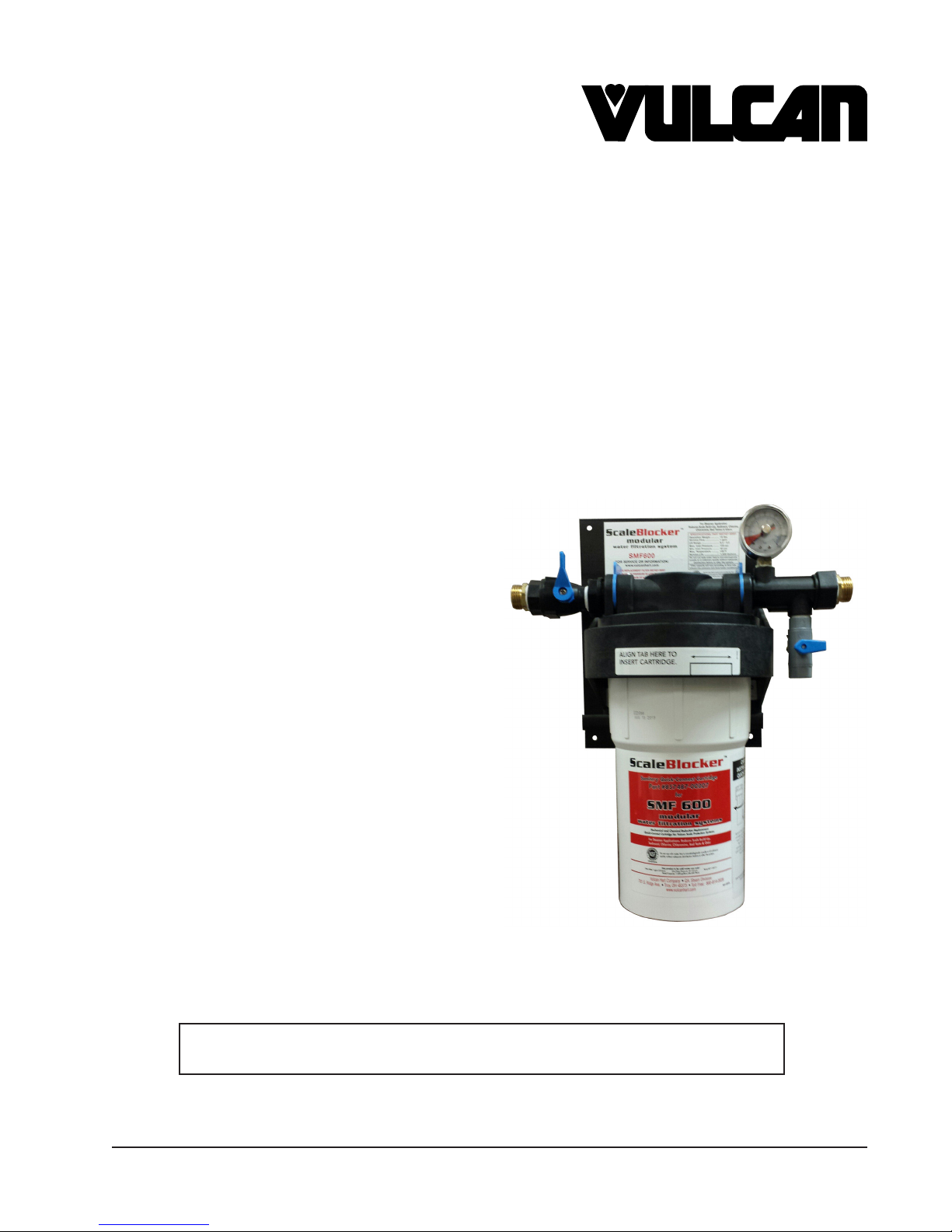
SCALEBLOCKER™
WATER FILTER SYSTEM
MODELS
SMF600
SMF620
INSTALLATION &
For additional information on Vulcan-Hart or to locate an authorized parts
and service provider in your area, visit our website at www.vulcanequipment.com
VULCAN-HART
DIVISION OF ITW FOOD EQUIPMENT GROUP, LLC
WWW.VULCANEQUIPMENT.COM TECHNICAL SUPPORT (800) 814-2028
SMF600
3600 NORTH POINT BLVD.
BALTIMORE, MD 21222
FORM 37510 (August 2016)
Page 2
IMPORTANT FOR YOUR SAFETY
THIS MANUAL HAS BEEN PREPARED FOR PERSONNEL QUALIFIED TO INSTALL
THIS EQUIPMENT, WHO SHOULD PERFORM THE INITIAL FIELD START-UP AND
ADJUSTMENTS OF THE EQUIPMENT COVERED BY THIS MANUAL.
IMPROPER INSTALLATION, ADJUSTMENT,
ALTERATION, SERVICE OR MAINTENANCE CAN CAUSE
PROPERTY DAMAGE, INJURY OR DEATH. READ
THE INSTALLATION, OPERATING AND MAINTENANCE
INSTRUCTIONS THOROUGHLY BEFORE INSTALLING OR
SERVICING THIS EQUIPMENT.
RETAIN THIS INSTRUCTION MANUAL FOR FUTURE
REFERENCE
© VULCAN, 2016
— 2 —
Page 3

TABLE OF CONTENTS
GENERAL ...........................................................................................................................................4
Water Quality Statement ................................................................................................................4
Models ...........................................................................................................................................4
Standard Features .........................................................................................................................5
INSTALLATION ...................................................................................................................................6
Unpacking ......................................................................................................................................6
Test the Water ................................................................................................................................6
Installation Instructions ..................................................................................................................6
Mounting ........................................................................................................................................6
Water Connections ........................................................................................................................7
Reversing the Inlet and Outlet .................................................................................................8
OPERATION ........................................................................................................................................8
Initializing Water Filter ...................................................................................................................8
CLEANING ..........................................................................................................................................9
Routine Deliming ...........................................................................................................................9
MAINTENANCE ..................................................................................................................................9
Cartridge Change/Replacement Schedule ....................................................................................9
Replacement Cartridge Filter Kits ................................................................................................10
Equipment Dealer Orders ......................................................................................................10
Service Parts Orders .............................................................................................................10
Cartridge Changing Instructions ..................................................................................................10
Leaks ...........................................................................................................................................11
Leaks at Threaded Connection Points ...................................................................................11
Leaks at Junction of Fittings to Filter Head ............................................................................11
Leaks Between Cartridge and Filter Head ............................................................................. 11
Warranty Registration ..................................................................................................................12
Vulcan ....................................................................................................................................12
Hobart ....................................................................................................................................12
Service .........................................................................................................................................12
Technical Support ..................................................................................................................12
— 3 —
Page 4
INSTALLATION, OPERATION AND CARE OF
SCALEBLOCKER™ WATER FILTER SYSTEM
SAVE THESE INSTRUCTIONS FOR FUTURE USE
GENERAL
Vulcan water lters are produced with quality workmanship and material. Proper installation, usage
and maintenance of your water lter will result in many years of satisfactory performance.
It is suggested that you thoroughly read this entire manual and carefully follow all of the instructions
provided.
The water lter system conforms to ANSI/NSF Standard 53 and ANSI/NSF Standard 42 for the specic
performance claims as veried and substantiated by test data.
WATER QUALITY STATEMENT
The fact that a water supply is potable is no guarantee that it is suitable for steam generation. Systems
are not to be used where water is microbiologically unsafe or with water of unknown quality without
adequate disinfections before and after use. Other factors affecting steam generation include iron
content, amount and type of chlorination (Chlorine & Chloramines), and dissolved gases. Water supplies
vary from state to state and from locations within a state.
As with all steam related products, water ltration and regular lter replacements coupled
with routine Deliming are required.
MODELS
SMF600 SMF620
Rated Capacity (Gallons) 7,500 Rated Capacity 12,000
Flow Rate (GPM) 2 Flow Rate 4
Supplied Water Pressure* 40-125 PSI Supplied Water Pressure* 40-125 PSI
Supplied Water Temperature 45-100°F Supplied Water Temperature 45-100°F
*For cold water use only.
— 4 —
Page 5
STANDARD FEATURES
• Single cartridge scale reduction hollow carbon lter system
• Mounting bracket
3
/4" Male GHT/ 3/4" NPTF inlet, outlet and cold water condensate connections.
•
• Main shutoff valve
• Test port with valve
• Pressure gauge
• Class 5 recyclable cartridge
• Reduce Scale, Chloramines, Chlorine, Sediment, Bad Tastes and Odors, Total Organic
Compounds, Tannins and Trihalomethanes
NOTE: This appliance is manufactured for commercial installation only and not intended for home
use.
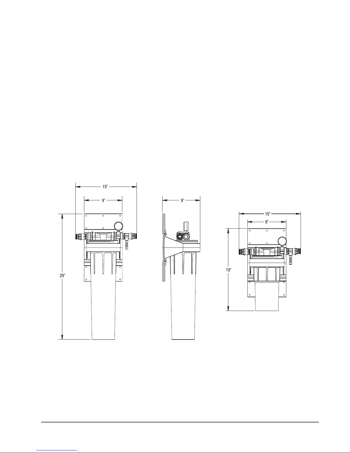
SMF620-SYSTEM TYPICAL SIDE VIEW SMF600-SYSTEM
— 5 —
Page 6
INSTALLATION
UNPACKING
This lter system was inspected before leaving the factory. The carrier assumes full responsibility for
the safe delivery upon acceptance of the shipment. Check for possible shipping damage immediately
after receipt.
If the lter system is found to be damaged, complete the following steps:
1. Carrier must be notied within 5 business days of receipt.
2. Carrier’s local terminal must be notied immediately upon discovery (note time, date, and who
was spoken to), and follow up and conrm with written or electronic communication.
3. All original packing materials must be kept for inspection purposes.
4. The lter system cannot have been moved, installed, or modied.
5. Notify Vulcan Customer Service immediately at 800-814-2028.
TEST THE WATER
Before installing your lter system test the water with a test strip provide with the lter system. If the
water TOTAL HARDNESS test is 17.5 grains (300 PPM) or below continue with installation. If the TOTAL
HARDNESS tests results are higher than 17.5 grains (300 PPM), call your dealer or technical support
immediately. The technical support contact information can be found in the MAINTENANCE Section.
INSTALLATION INSTRUCTIONS
Read all instructions and labels for lter system
before beginning. Position the lter upright on a
horizontal surface without obstructions. Locate
a position that is close to the equipment it will be
supplying water to, where it is out of the way of
possible damage from day-to-day operations,
and where it is accessible for cartridge change
out when needed. There should be a 6” minimum
bottom clearance.
MOUNTING
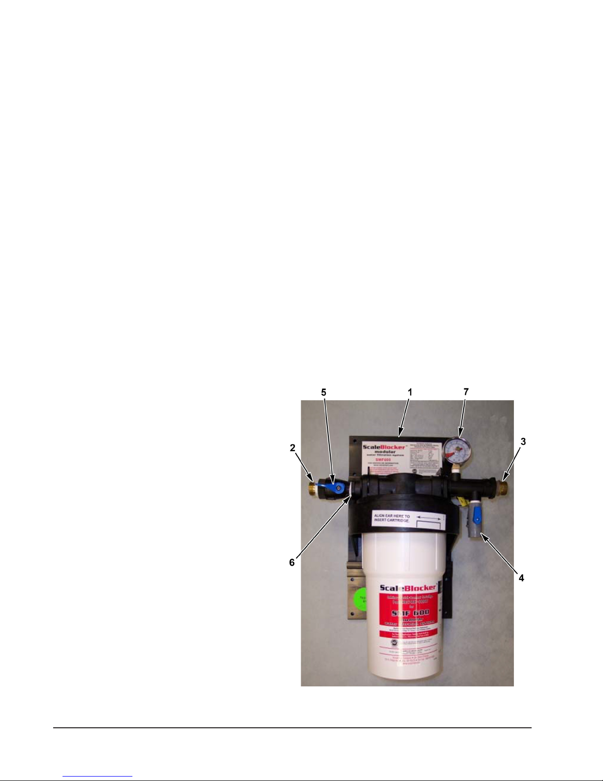
Measure back plate(Fig.1, Item 1) of lter system
and mark hole mounting locations on wall.
Ensure marks are level, and then drill holes for
anchors (if needed). Anchors must be properly
matched, to allow for wet weight of lter system
and water lines. Secure water lter system to
wall at all four mounting locations.
Fig. 1
— 6 —
Page 7

WATER CONNECTIONS
3
1. Use appropriate
/4" ttings, plumbing, or hoses to allow for a ow rate of lter. Do not over
tighten ttings into plastic parts! Backhold the ttings with a wrench or slip joint pliers! Warranty
will be voided if parts are cracked and/or broken due to misuse and/or over-tightening! Use only
approved ttings.
2. Connect water lter inlet to cold water supply to inlet tting (Fig. 1, Item 6). If hard plumbed do
not solder within 12" of plastic parts.
1
3. From ltered outlet and the condensate outlet of water lter use no less than
/2" ID tubing to the
steamer.
4. Connect ltered /treated water outlet (Fig. 1, connection with pressure gauge and Item 3 front)
to the ltered/treated water inlet on the rear of the steamer.
5. Connect unltered/untreated water outlet (Fig. 1, elbow rear Item 3 front) to the unltered/untreated
water inlet on the rear of the steamer.
6. There should not be any plumbing connections made to the test port below the pressure gauge.
This is for ltered water sampling only (Fig. 1, Item 4).
7. Verify adequate “DYNAMIC” ow rate and pressure is supplied to equipment during peak demand
and meets the specs for the lter. The pressure gauge should never drop below 20 PSI during
operation and not exceed 60 PSI.
8. If during equipment operation the supply plumbing is moving during or the steamer water ll
valve is excessively noisy, water hammer exists. A water hammer arrestor must be installed or
premature solenoid valve failure will occur or water leaks will develop.
9. This system is for single point connection only. It must not be connected to any other equipment.
10. Installation of backow preventers, vacuum breakers, water hammer arrestors, and other specic
code requirements is the responsibility of the owner and installer in compliance with local codes.
— 7 —
Page 8
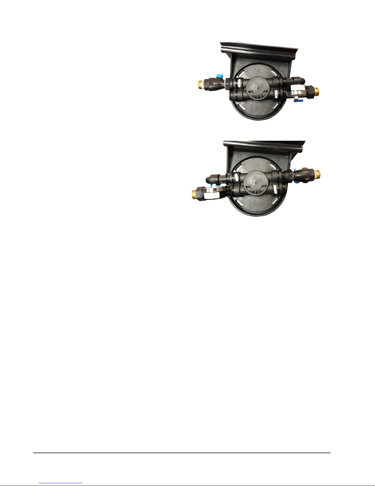
Reversing the Inlet and Outlet
NOTE: When reversing the water connections on
the ltration system you must keep all parts on the
original line on the lter head.
NOTE: Once the blue retaining ring has been removed
pull the section straight out to remove it.
1. Using a at screwdriver remove both blue
retaining rings.
2. The photo in Figure 2 shows the lter in the
as received condition with the blue retaining
clips removed. Remove all sections from the
lter head by sliding them straight out. Due to
interference the pressure relief valve will have
to be removed last.
3. The photo in Figure 3 shows the lter with the
inlet and outlet components reversed. Due to
interference the pressure relief valve will need
to be reinstalled rst.
NOTE: The pressure gauge will need to be rotated
180 degrees counterclockwise so it can be viewed from
the front of the water ltration system. Tightening it
clockwise will crack the plastic tee. Use Teon tape
to seal any leaks.
Fig. 2
Fig. 3
4. Reinstall the blue retaining clips.
5. Move the inlet and outlet stickers to the opposite side of the lter head.
OPERATION
INITIALIZING WATER FILTER
1. Check to be sure that the cartridge is properly installed. Do this by turning the cartridge
counterclockwise when looking at the bottom of the cartridge, and then back clockwise until the
positive stop is felt (Fig. 4).
2. Turn inlet ball valve to the “On” position (handle horizontal) slowly allowing water to ll lter
system (Fig. 1, Item 5).
3. Purge the cartridge so that there is no air remaining by depressing the red button until a steady
stream of water comes out (Fig. 1, Item 6).
4. Purge all air from the water lines by activating equipment for water use.
5. System is now operational. Go back and check connections for possible leaks and reseal where
needed.
— 8 —
Page 9

CLEANING
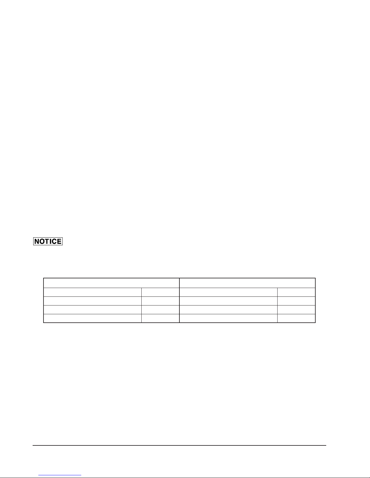
ROUTINE DELIMING
When ScaleBlocker ® water treatment system is
used, preventative maintenance along with cartridge
replacement must be performed every 6 months. Water
conditions may require additional deliming, see chart
at right.
Use ScaleRelease (14 oz) P/N 00-854893-00013 for
deliming; 14 Oz. for counter tops, 28 Oz. required for
oor models.
The cooling water supplied to the steamer is not treated.
White vinegar poured down the cavity drains will prevent
scale from forming in the drain system. Pour one
cup (8 Oz.) of white vinegar down each cavity drain at
the end of the day. Make sure the unit has been off for
5-10 minutes before adding the vinegar to the drain.
Hardness
(Grains)
0 to 5 6 Months
5 to 10 3 Months
10 to 15 Monthly
15 to 20 2 Weeks
20+
Hardness
(Grains)
0 to 5 2 Months
5 to 10 Monthly
10 to 15 2 Weeks
15 to 20 Once a Week
20+ Twice a Week
Steam Generator
Deliming Schedule
Other Water Treatment
Is Required
Drain Deliming
Schedule
MAINTENANCE
CARTRIDGE CHANGE/REPLACEMENT SCHEDULE
NOTE: The Scale Blocker pm kit (i.e. lter) must be replaced every six months, (every twelve months
for K-12 180 Day Schools). In addition, the equipment needs to be regularly delimed based on the water
hardness at the location (see chart above). Failure to perform all required preventive maintenance
will void water related warranty on the equipment.
• Gallon capacity of lter cartridge will vary according to ow rate, inlet pressure and local water
conditions. Replace cartridge immediately if outlet pressure gauge is less than 20 psi or before
end of capacity life (Maximum cartridge operating life 6 months). Fluctuations of pressure
will occur and can be seen at gauge during heavy and light usage. Inspect gauge during worst
case heavy water usage (Fig. 1, Item 7). It is recommended to change PRIOR to nearing end
of cartridge life.
• Failure to replace cartridge every 6 months will result in hard scale build up in the steam
generator. Pitting, rusting and discoloration will occur from Chloramines and Chlorine
in water supply and will damage your steamer.
• This lter reduces hard scale build-up due to hardness or other contaminants that may be in
water.
• Hardness higher than 5 grains will result in some soft scale build-up. Routine deliming is required
to remove soft scale build-up, see deliming chart.
— 9 —
Page 10

REPLACEMENT CARTRIDGE FILTER KITS
Equipment Dealer Orders
• SMF600-PMKIT – 7,500 Rated Capacity (Gallons)
• SMF620-PMKIT – 12,000 Rated Capacity (Gallons)
Service Parts Orders
• 00-857487-00600 – 7,500 Rated Capacity (Gallons)
• 00-857487-00620 – 12,000 Rated Capacity (Gallons)
CARTRIDGE CHANGING INSTRUCTIONS
1. Shut off inlet valve.
2. Push “Red” pressure relief button located at left end
of SMF lter system to relieve pressure until no more
water comes out.
1
3. Grasp lter cartridge, turn counterclockwise
/4 turn
(when viewed from bottom) and pull downward about
1
/2" to remove the lter cartridge (Fig. 4). Properly
1
dispose of old cartridge.
4. See lter cartridge label for proper replacement
cartridge part number.
5. Remove and discard the “Red” sanitary cap from the
top of the new cartridge. Be sure to apply sufcient
lubrication (supplied) to the O-Rings.
6. Align ear on cartridge with notch in lter head and
push upwards to insert. Be sure to push cartridge all
the way in.
7. Turn cartridge clockwise (when viewed from bottom)
1
/8 turn until a denite stop is felt and cartridge is
sealed (Fig. 4). Hand tight is sufcient.
Fig. 4
— 10 —
Page 11

LEAKS
All Water Filter Systems are factory pressure tested. It is normal to experience leaks of a few drops
of water at the various O-Ring sealed junction points at initial start-up only. This will subside after a
few minutes as soon as the O-Rings become under pressure and seat properly. For any leaks lasting
longer than this, or those that are more than a few drops, please see the troubleshooting points below.
NOTE: The inlet valve must be turned “OFF” (handle in vertical position), and pressure relieved by
pushing the “Red” pressure relief button before attempting to x any leakage problems or removing
the lter cartridge.
Leaks at Threaded Connection Points
This type of leak should be repaired by removing the tting, removing existing Teon tape, and
reapplying Teon tape. Do not attempt to repair by tightening the tting more! Overtightening ttings
into plastic parts may cause the plastic to crack. This type of damage is considered abuse, and not
covered by the warranty!
Leaks at Junction of Fittings to Filter Head
If leaking persists at the junction points, remove the retainer clip carefully by inserting a screwdriver
or other object into to the hole and gently prying “UP” to remove. Gently remove the leaking tting
by “pulling straight out”. Apply additional lubricant (supplied) to the O-Ring and re-insert the tting by
gently “pushing all the way in” until the shoulder on the tting contacts the lter head. Examine the
retaining clip for any cracks from removal and re-insert by “pushing straight down” until it is all the way
in. If retaining clip is cracked or stretched in any way, discard it and use a new one (supplied). If the
above procedure does not cure the leak, repeat the processes above, replacing the O-Ring (supplied).
Leaks Between Cartridge and Filter Head
While looking at the top of the lter system, grasp the
cartridge and turn slightly counterclockwise, when
viewed from bottom and then back clockwise, making
sure that the ears on the cartridge are fully engaged
into the lter head. The round locking tab in the lter
head will be engaged into the half-round recess in the
cartridge ear (Fig. 5).
If leakage persists, remove cartridge by following the
procedures of the Cartridge Changing Instructions.
Inspect the O-Ring on the top of the cartridge for
damage. Replace with a new O-Ring (supplied) and
lubricate well with lubricant supplied. Replace the
cartridge per instructions (Fig. 5).
Fig. 5
— 11 —
Page 12

WARRANTY REGISTRATION
Vulcan
The lter replacement must be registered online at www.itwltreg.com. Failure to register your lter
may result in delayed claims payment.
On the homepage select new lter registration or replacement lter registration.
NOTE: If this is a replacement lter the cells will be backlled. Please verify the accuracy of all
information before submitting the registration.
If this is a new piece of equipment click the black New Filter Installation icon. Is this lter for a steamer
or combi oven? Click the appropriate icon. Input all Specied information regarding the Business /
End User Location, Contact Information*, Filter System Information and Water Test Strip Information.
Once all information has been entered click the Submit button at the bottom of the page.
*Due to high amounts of employee turnover in the food service industry Vulcan recommends that all
replacement reminders be sent to a group e-mail address rather than to an individual.
Hobart
All Hobart registrations need to be registered online.
SERVICE
To obtain service and parts information concerning this unit, contact the Vulcan-Hart Service Agency
in your area, or contact the Vulcan-Hart Service Department at the address or phone number shown
on the front cover of this manual.
Parts and service are also available at www.vulcanequipment.com.
Technical Support
Vulcan Steamers – 800-814-2028 www.vulcanequipment.com
www.steamtech@itwfeg.com
Hobart Steamers – 888-4HOBART www.hobartservice.com
— 12 —F-37510 (August 2016) PRINTED IN U.S.A.
Page 13

— 12 —F-37510 (août 2016) IMPRIMÉ AUX ÉTATS-UNIS.
Hobart Steamers — 888 4HOBART www.hobartservice.com
www.steamtech@itwfeg.com
Vulcan Steamers — 1 800 814-2028 www.vulcanequipment.com
Assistance technique
Les pièces et services sont également disponibles sur notre site www.vulcanequipment.com.
numéro de téléphone indiqués sur la page de couverture de ce manuel.
de service Vulcan-Hart de votre région ou avec le service auxiliaire de Vulcan-Hart à l’adresse ou au
Pour obtenir des renseignements sur l’entretien et les pièces de cette unité, communiquez avec l’agence
ENTRETIEN
Tous les enregistrements Hobart doivent être effectués en ligne.
Hobart
d’envoyer les rappels de remplacement à un groupe de courriels plutôt qu’à un seul individu.
*En raison du fort roulement de personnel dans l’industrie alimentaire, Vulcan vous recommande
sur le bouton Soumettre situé au bas de la page.
le système de fi ltration et les bandelettes réactives. Une fois tous les renseignements inscrits, cliquez
les renseignements demandés concernant l’entreprise, l’emplacement d’utilisation, les coordonnées*,
Ce fi ltre servira-t-il pour une marmite ou un four mixte? Cliquez sur l’icône appropriée. Saisissez tous
S’il s’agit d’une nouvelle pièce d’équipement, cliquez sur l’icône noir Installation d’un nouveau fi ltre.
l’exactitude des renseignements avant de soumettre l’enregistrement.
REMARQUE : S’il s’agit d’un fi ltre de remplacement, les cellules seront remplies. Veuillez vérifi er
de remplacement.
Sur la page d’accueil, sélectionnez Enregistrement d’un nouveau fi ltre ou Enregistrement d’un fi ltre
fi ltre pourrait causer un retard de remboursement en cas de réclamation.
Le fi ltre de remplacement doit être enregistré en ligne au www.itwfi ltreg.com. Ne pas enregistrer votre
Vulcan
ENREGISTREMENT DE LA GARANTIE
Page 14

Fig. 5
— 11 —
place en suivant les instructions (fi g. 5).
à l’aide du lubrifi ant inclus. Remettez la cartouche en
par un nouveau joint torique (inclus) et bien lubrifi er
de la cartouche n’est pas endommagé. Remplacez-le
de fi ltre. Vérifi ez que le joint torique situé sur le dessus
suivant la procédure de remplacement de la cartouche
S’il y a toujours une fuite, enlevez la cartouche en
cercle dans l’ailette de la cartouche (fi g. 5).
la tête du fi ltre est engagé dans l’alvéole en demi-
dans la tête du fi ltre. L’onglet de verrouillage rond de
que les ailettes sur la cartouche sont bien engagées
de nouveau dans le sens horaire pour vous assurer
sens antihoraire, lorsque regardé de dessous, puis
la cartouche et faites-la tourner légèrement dans le
En regardant le dessus du système de fi ltration, tenez
Fuites entre la cartouche et la tête du fi ltre
joint torique (inclus).
pas le problème, répétez les étapes et remplacez le
une nouvelle (incluse). Si cette procédure ne règle
endommagée ou déformée, le jeter et en prendre
place en la poussant vers le bas jusqu’à ce qu’elle soit totalement enfoncée. Si l’agrafe de butée est
touche à la tête du fi ltre. Vérifi ez que l’agrafe de butée n’est pas endommagée, puis remettez-la en
de nouveau le raccord en le poussant doucement à sa position, jusqu’à ce que le coude du raccord
qui fuit en le tirant doucement à l’extérieur. Ajoutez du lubrifi ant (inclus) au joint torique, puis installez
un tournevis ou un autre objet dans le trou et en tirant doucement vers le haut. Enlevez le raccord
Si des fuites sont toujours présentes aux jonctions, enlevez délicatement l’agrafe de butée en insérant
Fuites à la jonction des raccords et de la tête du fi ltre
comme abusif et n’est pas couvert par la garantie!
serrer les raccords pourrait faire craquer la partie en plastique! Ce type de dommage est considéré
puis en enroulant du nouveau ruban. N’essayez pas de réparer la fuite en serrant plus le raccord! Trop
Ce type de fuite devrait être corrigé en enlevant le raccord et le ruban pour joint fi leté déjà en place,
Fuites à un point de connexion avec fi let
cartouche de fi ltre.
appuyant sur le détendeur de pression « rouge » avant d’essayer de corriger une fuite ou de retirer la
REMARQUE : La vanne d’entrée doit être fermée (poignée à la verticale) et le fi ltre dépressurisé en
important, veuillez consulter la section dépannage ci-dessous.
joints toriques et qu’ils prennent leur position. Pour toute fuite qui se prolonge ou dont le débit est plus
démarrage initial. Ces fuites cessent après quelques minutes, dès qu’une pression est appliquée aux
normal de remarquer des fuites de quelques gouttes d’eau aux joints toriques, mais seulement au
Tous les systèmes de fi ltration d’eau subissent un essai de résistance à la pression en usine. Il est
FUITES
Page 15

— 10 —
Fig. 4
/4 de
1
/2 po pour
1
/8 de tour jusqu’à
1
soit scellée (fi g. 4). Un serrage à la main est suffi sant.
ce qu’il n’y ait pas de mouvement et que la cartouche
regardant à partir du dessous) de
7. Faites tourner la cartouche dans le sens horaire (en
l’insérer. Assurez-vous de bien insérer la cartouche.
dans la tête du fi ltre, puis poussez vers le haut pour
6 . Alignez les ailettes de la cartouche qui ont une encoche
suffi samment de lubrifi ant (inclus) aux joints toriques.
nouvelle cartouche et le jeter. Assurez-vous d’ajouter
5. Enlevez le capuchon sanitaire « rouge » de la
connaître le numéro de pièce de remplacement.
4. Consultez l’étiquette de la cartouche de fi ltre pour
respectant la réglementation.
la retirer. (fi g. 4). Mettre la cartouche au rebut tout en
du dessous) tout en tirant vers le bas de 1
tour dans le sens antihoraire (en regardant à partir
3. Tenir la cartouche de fi ltre et la faire tourner de
la pression jusqu’à qu’il n’y ait plus d’eau qui s’écoule.
à la gauche du système de fi ltration SMF pour libérer
2. Appuyez sur le détendeur de pression « rouge » situé
1. Fermez la vanne d’entrée.
INSTRUCTIONS DE REMPLACEMENT DE LA CARTOUCHE
• 00-857487-00620 — Débit nominal de 12 000 (gallons)
• 00-857487-00600 — Débit nominal de 7 500 (gallons)
Commandes de pièces d’entretien
• SMF620-PMKIT — Débit nominal de 12 000 (gallons)
• SMF600-PMKIT — Débit nominal de 7 500 (gallons)
Commandes d’équipement chez le fournisseur
TROUSSES DE REMPLACEMENT DE LA CARTOUCHE DE FILTRE
Page 16

— 9 —
est nécessaire pour éliminer le tartre tendre, consultez le tableau de détartrage.
• Une eau d’une dureté supérieure à 5 grains produira du tartre tendre. Un détartrage régulier
présents dans l’eau.
• ce fi ltre réduit la formation de tartre dur causée par la dureté de l’eau ou d’autres contaminants
endommageront la marmite en produisant des piqûres, de la rouille et de la décoloration.
remplacée tous les 6 mois. Les chloramines et le chlore de l’approvisionnement en eau
• Du tartre dur se formera dans le générateur de vapeur si la cartouche n’est pas
est recommandé de remplacer la cartouche AVANT la fi n de sa durée de vie utile.
Vérifi ez le manomètre pendant les périodes de plus grandes utilisations (fi g. 1, élément 7). Il
et peuvent être observées au manomètre pendant les utilisations importantes et légères.
de vie maximale d’une cartouche est de 6 mois). Des variations de pression se produisent
indiquée à l’entrée est inférieure à 20 PSI ou avant la fi n de sa durée de vie utile (la durée
d’entrée et de la qualité de l’eau utilisée. Remplacez immédiatement la cartouche si la pression
• La capacité en gallons de la cartouche de fi ltre varie en fonction du débit, de la pression
préventif annulera la garantie en lien avec l’eau de l’équipement.
en fonction de la dureté de l’eau utilisée (voir le tableau plus haut). Ne pas effectuer cet entretien
12 mois pour le modèle K-12 180 Day Schools). De plus, l’équipement doit être régulièrement détartré
REMARQUE : La trousse Scale Blocker pm (c.-à-d. fi ltre) doit être remplacée tous les 6 mois (tous les
des drains
Horaire de détartrage
d’eau est requis
Un autre traitement
vapeur
du générateur de
Horaire de détartrage
20+ Deux fois semaine
15 à 20 Une fois semaine
10 à 15 aux 2 semaines
5 à 10 Tous les mois
0 à 5 2 mois
(grains)
Dureté
20+
15 à 20 aux 2 semaines
10 à 15 Tous les mois
5 à 10 3 mois
0 à 5 6 mois
(grains)
Dureté
REMPLACEMENT DE CARTOUCHE/HORAIRE DE REMPLACEMENT
ENTRETIEN
de 5 à 10 minutes avant de verser le vinaigre.
la fi n de la journée. Assurez-vous d’avoir fermé l’unité
une tasse (8 oz) de vinaigre blanc dans chaque drain à
préviendra la formation de dépôts de calcaire. Versez
pas traitée. L’ajout de vinaigre blanc dans les drains
L’eau de refroidissement acheminée à la marmite n’est
de comptoir, format 28 oz requis pour le modèle au sol.
854893-00013, pour le détartrage; 14 oz pour le modèle
Utilisez ScaleRelease (14 oz), numéro de pièce 00-
supplémentaire, consultez le tableau de droite.
mois. La qualité de l’eau peut imposer un détartrage
de la cartouche doivent être effectués tous les 6
est utilisé, l’entretien préventif et le remplacement
®
Lorsque le système de traitement de l’eau ScaleBlocker
ENTRETIEN DE DÉTARTRAGE
NETTOYAGE
Page 17

— 8 —
les fuites.
5. Le système est maintenant fonctionnel. Inspectez de nouveau le système et réparez, au besoin,
d’eau.
4. Purgez tout l’air des canalisations d’eau en démarrant l’équipement pour qu’il effectue un appel
fi let d’eau continu coule (fi g. 1, élément 6).
3. Purgez la cartouche pour qu’il n’y ait plus d’air en appuyant sur le bouton rouge jusqu’à ce qu’un
système de fi ltration (fi g. 1, élément 5).
2. Ouvrir lentement la vanne à bille (poignée à l’horizontale) pour permettre à l’eau de remplir le
horaire jusqu’à ce que vous trouviez la position d’arrêt (fi g. 4).
sens antihoraire (lorsque vous regardez au bas de la cartouche), puis à nouveau dans le sens
1. Vérifi ez que la cartouche est bien installée. Pour se faire, faites tourner la cartouche dans le
PREMIÈRE MISE EN MARCHE DU FILTRE À EAU
FONCTIONNEMENT
Fig. 3
Fig. 2
5. Replacez les autocollants d’entrée et de sortie sur les côtés opposés de la tête du fi ltre.
4. Réinstallez les agrafes de butées bleues.
pour joints fi letés pour sceller les fuites.
fera craquer le raccord en plastique. Utilisez du ruban
fi ltration d’eau. Le faire tourner dans le sens horaire
puissiez le consulter à partir de l’avant du système de
de 180° dans le sens antihoraire pour que vous
REMARQUE : Vous devrez faire pivoter le manomètre
être réinstallé en dernier.
d’interférences, le détendeur de pression devra
d’entrée et de sortie ont été inversés. En raison
3. La fi gure 3 présente le fi ltre dont les orifi ces
être retiré en dernier.
d’interférences, le détendeur de pression devra
en les faisant glisser à l’extérieur. En raison
Enlevez toutes les sections de la tête du fi ltre
reçu, mais sans les agrafes de butées bleues.
2. La fi gure 2 présente le fi ltre comme vous l’avez
les deux anneaux d’arrêt bleues.
1. À l’aide d’un tournevis à lame plate, enlevez
enlevée, tirez sur la section pour la faire sortir.
REMARQUE : Une fois l’anneau d’arrêt bleue
raccordements d’eau du système de fi ltration.
même ordre sur la tête du fi ltre si vous inversez les
REMARQUE : Conservez toutes les pièces dans le
Inverser l’orifi ce d’entrée et de sortie
Page 18

— 7 —
et autres éléments requis par le code en respectant les réglementations locales.
10. Vous êtes responsable d’ajoutes des disconnecteurs hydrauliques, renifl ards, dispositifs antibéliers
autre équipement.
9. Ce système est conçu pour être relié à un seul point de connexion. Il ne doit pas être relié à un
ou se crée une fuite d’eau.
antibélier doit être installé pour ne pas que se produise une défaillance prématurée de l’électrovanne
en eau de la marmite est très bruyante, vous pouvez ajouter un dispositif antibélier. Un dispositif
8. Si, pendant le fonctionnement de l’équipement, la plomberie bouge ou la vanne d’alimentation
pas excéder 60 PSI.
manomètre ne devrait jamais indiquer moins de 20 PSI pendant le fonctionnement et ne doit
pendant les périodes de grande demande et qu’ils répondent aux spécifi cations du fi ltre. Le
7. Assurez-vous qu’une pression et un débit « DYNAMIQUE » adéquat sont fournis à l’équipement
Cette prise sert exclusivement à échantillonner l’eau fi ltrée (fi g. 1, élément 4).
6. Il ne devrait pas y avoir de connexion de plomberie effectuée à la prise d’essai sous le manomètre.
l’entrée d’eau traitée/fi ltrée située à l’arrière de la marmite.
5. Branchez la sortie d’eau non traitée/fi ltrée (fi g. 1, arrière du coude et avant de l’élément 3) à
à l’entrée d’eau traitée/fi ltrée située à l’arrière de la marmite.
4. Branchez la sortie d’eau traitée/fi ltrée (fi g. 1, raccord avec manomètre et avant de l’élément 3)
de condensats du fi ltre à eau à la marmite.
/2 po de diamètre intérieur pour relier l’orifi ce de sortie et du raccord
1
3. Utilisez un tube d’au moins
plastique.
Si vous utilisez une plomberie à tuyaux rigides, ne pas souder à moins de 12 po des pièces en
2. Branchez le raccord de l’orifi ce d’entrée du fi ltre à eau à une source d’eau froide (fi g. 1 élément 6).
/4 po nécessaires pour acheminer le bon
3
que les raccords approuvés.
craquées ou brisées en raison d’une mauvaise utilisation ou d’un serrage excessif. N’utilisez
à l’aide d’une clé ou d’une pince à joint coulissant! La garantie est annulée si des pièces sont
débit au fi ltre. Ne serrez pas trop les raccords sur les parties en plastique! Tenir les raccords
1. Utilisez les raccords, la plomberie ou les tuyaux de
RACCORDEMENTS D’EAU
Page 19

Fig. 1
— 6 —
d’ancrage.
système de fi ltration au mur aux quatre points
des tuyaux lorsqu’ils sont alimentés. Fixez le
pouvoir supporter le poids du système et
l’encrage (au besoin). Les encrages doivent
sont de niveau, puis percez les trous pour
fi xation au mur. Assurez-vous que les marques
système de fi ltration et marquez les trous de
Mesurez la plaque arrière (fi g. 1, élément 1) du
INSTALLATION
positionné à au moins 6 po du sol.
remplacer la cartouche. Le système devrait être
que l’emplacement vous permet de facilement
par les activités quotidiennes. Assurez-vous
isolé pour que l’appareil ne soit pas endommagé
être approvisionné en eau, mais suffi samment
emplacement situé près de l’équipement devant
surface horizontale dégagée. Trouvez un
l’installation. Placez le fi ltre debout sur une
système de fi ltration avant de procéder à
Lire toutes les instructions et étiquettes du
INSTRUCTIONS D’INSTALLATION
ENTRETIEN.
technique sont inscrites dans la section
immédiatement avec votre fournisseur ou l’assistance technique. Les coordonnées de l’assistance
l’installation. Si la DURETÉ TOTALE de l’eau est supérieure à 17,5 grains (300 ppm), communiquez
avec le système. Si la DURETÉ TOTALE de l’eau est de 17,5 grains ou moins (300 ppm), continuez
Avant d’installer votre système de fi ltration, vérifi ez l’eau à l’aide d’une bandelette réactive fournie
ÉVALUATION DE L’EAU
5. Notifi ez le service à la clientèle Vulcan immédiatement au 1 800 814-2028.
4. Le système de fi ltration ne doit pas avoir été déplacé, installé ou modifi é.
3. Tous les matériaux d’emballage originaux doivent être conservés aux fi ns d’inspection.
confi rmez-la au moyen de communication écrite ou électronique.
constaté (notez l’heure, la date et la personne de contact), faites un suivi de la notifi cation et
2. La gare locale de la société de transport doit être notifi ée immédiatement une fois le dommage
1. La société de transport doit être notifi ée dans les 5 jours ouvrables suivant la réception.
Si vous constatez que le système de fi ltration est endommagé, procédez comme suit :
dommages possibles d’expédition immédiatement à la réception de la marmite.
responsabilité de la livraison en bon état puisqu’elle accepte d’effectuer l’expédition. Vérifi ez les
Ce système de fi ltration a été inspecté avant de quitter l’usine. La société de transport assume l’entière
DÉBALLAGE
INSTALLATION
Page 20

— 5 —
SMF620-SYSTEM VUE NORMALE DE CÔTÉ SMF600-SYSTEM
/4 po NPTF, orifi ce de sortie et raccords de condensats
3
/4 po GHT mâle
3
pour une utilisation domestique.
REMARQUE : Cet appareil est conçu pour une utilisation commerciale seulement, il n’est pas conçu
totaux, tannins et trihalométhanes
• Réduit : tartre, chloramines, chlore, sédiment, mauvais goût et odeurs, composées organiques
• Cartouche recyclable classe 5
• Manomètre
• Prise d’essai avec soupape
• Soupape d’arrêt principale
d’eau froide.
• Orifi ce d’entrée de
• Support d’installation
• Système de fi ltre au charbon évidé à cartouche unique avec réduction du tartre
CARACTÉRISTIQUES STANDARDS
Page 21

— 4 —
*Utilisez de l’eau froide seulement.
Température de l’eau à l’entrée* 45 à 100 °F Température de l’eau à l’entrée* 45 à 100 °F
Pression d’eau à l’entrée* 40 à 125 PSI Pression d’eau à l’entrée* 40 à 125 PSI
Débit (gallons par minute) 2 Débit 4
Débit nominal (gallons) 7 500 Débit nominal 12 000
SMF600 SMF620
MODÈLES
GÉNÉRALITÉS
des fi ltres, en plus du détartrage régulier, représentent un entretien nécessaire.
Comme avec tous les appareils à vapeur, la fi ltration de l’eau et le remplacement fréquent
en eau varie d’un état à l’autre et d’un lieu à un autre dans l’état.
la quantité et le type de chlore (chlore et chloramines), ainsi que les gaz dissous. L’approvisionnement
décontamination appropriée. D’autres facteurs affectent la production de vapeur comme la teneur en fer,
potable microbiologiquement ou si la qualité de l’eau est inconnue avant et après une utilisation sans
pour la production de vapeur. Ces systèmes ne doivent pas être utilisés lorsque l’eau est non
Le fait que l’approvisionnement en eau est potable n’est pas une garantie que l’eau est appropriée
QUALITÉ DE L’EAU
indiqué, puisque vérifi é et appuyé par de nombreuses données.
Le système de fi ltration d’eau est conforme à la norme ANSI/NSF 53 et 42 pour le rendement spécifi que
soigneusement toutes les instructions fournies.
Nous vous recommandons de lire attentivement ce manuel dans son intégralité et de suivre
rendement effi cace.
Une installation, une utilisation et un entretien appropriés du fi ltre à eau offriront plusieurs années de
Les fi ltres à eau Vulcan sont produits par une main-d’œuvre qualifi ée et avec des matériaux de qualité.
CONSERVEZ CES INSTRUCTIONS AUX FINS DE RÉFÉRENCES ULTÉRIEURES
SYSTÈME DE FILTRATION D’EAU SCALEBLOCKER™
INSTALLATION, FONCTIONNEMENT ET ENTRETIEN DU
Page 22

— 3 —
Assistance technique .............................................................................................................12
Entretien ......................................................................................................................................12
Hobart ....................................................................................................................................12
Vulcan ....................................................................................................................................12
Enregistrement de la garantie .....................................................................................................12
Fuites entre la cartouche et la tête du fi ltre............................................................................12
Fuites à la jonction des raccords et de la tête du fi ltre...........................................................12
Fuites à un point de connexion avec fi let...............................................................................12
Fuites ...........................................................................................................................................11
Instructions de remplacement de la cartouche ............................................................................11
Commandes de pièces d’entretien ........................................................................................11
Commandes d’équipement chez le fournisseur.....................................................................10
Trousses de remplacement de la cartouche de fi ltre ...................................................................10
Remplacement de cartouche/horaire de remplacement ..............................................................10
ENTRETIEN ........................................................................................................................................9
Entretien de détartrage ..................................................................................................................9
NETTOYAGE .......................................................................................................................................9
Première mise en marche du fi ltre à eau .......................................................................................9
FONCTIONNEMENT ...........................................................................................................................9
Inverser l’orifi ce d’entrée et de sortie .......................................................................................8
Raccordements d’eau ....................................................................................................................7
Installation .....................................................................................................................................7
Instructions d’installation ...............................................................................................................7
Évaluation de l’eau ........................................................................................................................6
Déballage ......................................................................................................................................6
INSTALLATION ...................................................................................................................................6
Caractéristiques standards ............................................................................................................5
Modèles .........................................................................................................................................4
Qualité de l’eau ..............................................................................................................................4
GÉNÉRALITÉS ...................................................................................................................................4
TABLE DES MATIÈRES
Page 23

— 2 —
© VULCAN, 2016
ULTÉRIEURE
CONSERVEZ CE MANUEL AUX FINS DE RÉFÉRENCE
ÉQUIPEMENT.
L’ENTRETIEN AVANT D’INSTALLER OU D’ENTRETENIR CET
RELATIVES À L’INSTALLATION, AU FONCTIONNEMENT ET À
VOIRE LA MORT. LISEZ ATTENTIVEMENT LES INSTRUCTIONS
PEUT PROVOQUER DES DOMMAGES, DES BLESSURES
ALTÉRATION, UN SERVICE OU UN ENTRETIEN INAPPROPRIÉ
UNE INSTALLATION, UN RÉGLAGE, UNE
SUR LE TERRAIN DE L’ÉQUIPEMENT DÉCRIT DANS LE PRÉSENT MANUEL.
ÉQUIPEMENT, QUI DOIT EFFECTUER LE DÉMARRAGE ET LES RÉGLAGES INITIAUX
CE MANUEL EST DESTINÉ AU PERSONNEL QUALIFIÉ POUR INSTALLER CET
IMPORTANT POUR VOTRE SÉCURITÉ
Page 24

FORMULAIRE 37510 (août 2016)
BALTIMORE, MD 21222
3600 NORTH POINT BLVD.
SMF600
WWW.VULCANEQUIPMENT.COM ASSISTANCE TECHNIQUE 1 800 814 2028
DIVISION DE ITW FOOD EQUIPMENT GROUP, LLC
VULCAN-HART
pièces ou de services dans votre région, visitez notre site à l’adresse www.vulcanequipment.com
Pour de plus amples renseignements sur Vulcan-Hart ou pour trouver un fournisseur agréé de
SMF620
SMF600
MODÈLES
SCALEBLOCKER™
SYSTÈME DE FILTRATION D’EAU
ET D’UTILISATION
MANUEL D’INSTALLATION
 Loading...