

Page 1

!"#"$%&'(%)*+#"$*%,$-%.$$/-00)))1.,(+&(2(*"3.$14&5
%65,"7%&'(%$*4.8"4,7%#'//&($%,$-%/(&9'4$#'//&($:.,(+&(2(*"3.$14&5
Owner’s Manual & Safety Instructions
Save This Manual%Keep this manual for the safety warnings and precautions, assembly,
operating, inspection, maintenance and cleaning procedures. Write the product’s serial number in the
back of the manual near the assembly diagram (or month and year of purchase if product has no number).
Keep this manual and the receipt in a safe and dry place for future reference.
When unpacking, make sure that the product is intact
and undamaged. If any parts are missing or broken,
please call 1-<?>-1-888-380-0318 as soon as possible.
Copyright© 2017 by Harbor Freight Tools®. All rights reserved.
No portion of this manual or any artwork contained herein may be reproduced in
any shape or form without the express written consent of Harbor Freight Tools.
Diagrams within this manual may not be drawn proportionally. Due to continuing
improvements, actual product may differ slightly from the product described herein.
To ol s re q u ir e d f o r a s s e mb l y a n d s e r vi c e m a y n o t b e in c l ud e d .
;*,9%$."#%5,$*(",7%+*2&(*%'#"83%$."#%/(&9'4$1%
<,"7'(*%$&%9&%#&%4,8%(*#'7$%"8%#*("&'#%"8='(>1%
?@!6%ABC?%D@EF@G1
Owner’s Manual & Safety Instructions
Save This Manual%Keep this manual for the safety warnings and precautions, assembly,
operating, inspection, maintenance and cleaning procedures. Write the product’s serial number in the
back of the manual near the assembly diagram (or month and year of purchase if product has no number).
Keep this manual and the receipt in a safe and dry place for future reference.
When unpacking, make sure that the product is intact
and undamaged. If any parts are missing or broken,
please call 1-888-380-0318 as soon as possible.
Copyright© 2017 by Harbor Freight Tools®. All rights reserved.
No portion of this manual or any artwork contained herein may be reproduced in
any shape or form without the express written consent of Harbor Freight Tools.
Diagrams within this manual may not be drawn proportionally. Due to continuing
improvements, actual product may differ slightly from the product described herein.
To ol s re q u ir e d f o r a s s e mb l y a n d s e r vi c e m a y n o t b e in c l ud e d .
;*,9%$."#%5,$*(",7%+*2&(*%'#"83%$."#%/(&9'4$1%
<,"7'(*%$&%9&%#&%4,8%(*#'7$%"8%#*("&'#%"8='(>1%
?@!6%ABC?%D@EF@G1
Owner’s Manual & Safety Instructions
Save This Manual%Keep this manual for the safety warnings and precautions, assembly,
operating, inspection, maintenance and cleaning procedures. Write the product’s serial number in the
back of the manual near the assembly diagram (or month and year of purchase if product has no number).
Keep this manual and the receipt in a safe and dry place for future reference. 17d
When unpacking, make sure that the product is intact
and undamaged. If any parts are missing or broken,
please call 1-888-380-0318 as soon as possible.
Copyright© 2017 by Harbor Freight Tools®. All rights reserved.
No portion of this manual or any artwork contained herein may be reproduced in
any shape or form without the express written consent of Harbor Freight Tools.
Diagrams within this manual may not be drawn proportionally. Due to continuing
improvements, actual product may differ slightly from the product described herein.
To ol s re q u ir e d f o r a s s e mb l y a n d s e r vi c e m a y n o t b e in c l ud e d .
;*,9%$."#%5,$*(",7%+*2&(*%'#"83%$."#%/(&9'4$1%
<,"7'(*%$&%9&%#&%4,8%(*#'7$%"8%#*("&'#%"8='(>1%
?@!6%ABC?%D@EF@G1
Page 2
Page 2 <&(%$*4.8"4,7%H'*#$"&8#I%/7*,#*%4,77%JKLLLKMLNKNMJL1 Item 63618
?@<6AO D@CEA6E@EP6Q@?CP%R6GSCET R6GSCET%ACU?
SETUP
?@<6AO D@CEA6E@EP6Q@?CP%R6GSCET R6GSCET%ACU?
SETUP
A,+7*%&2%P&8$*8$#
Safety ......................................................... 2
Specifications ............................................. 7
Setup .......................................................... 8
Basic Welding ............................................ 12
Welding Tips .............................................. 20
Maintenance and Service .......................... 24
Parts List and Diagrams ............................ 25
Warranty .................................................... 28
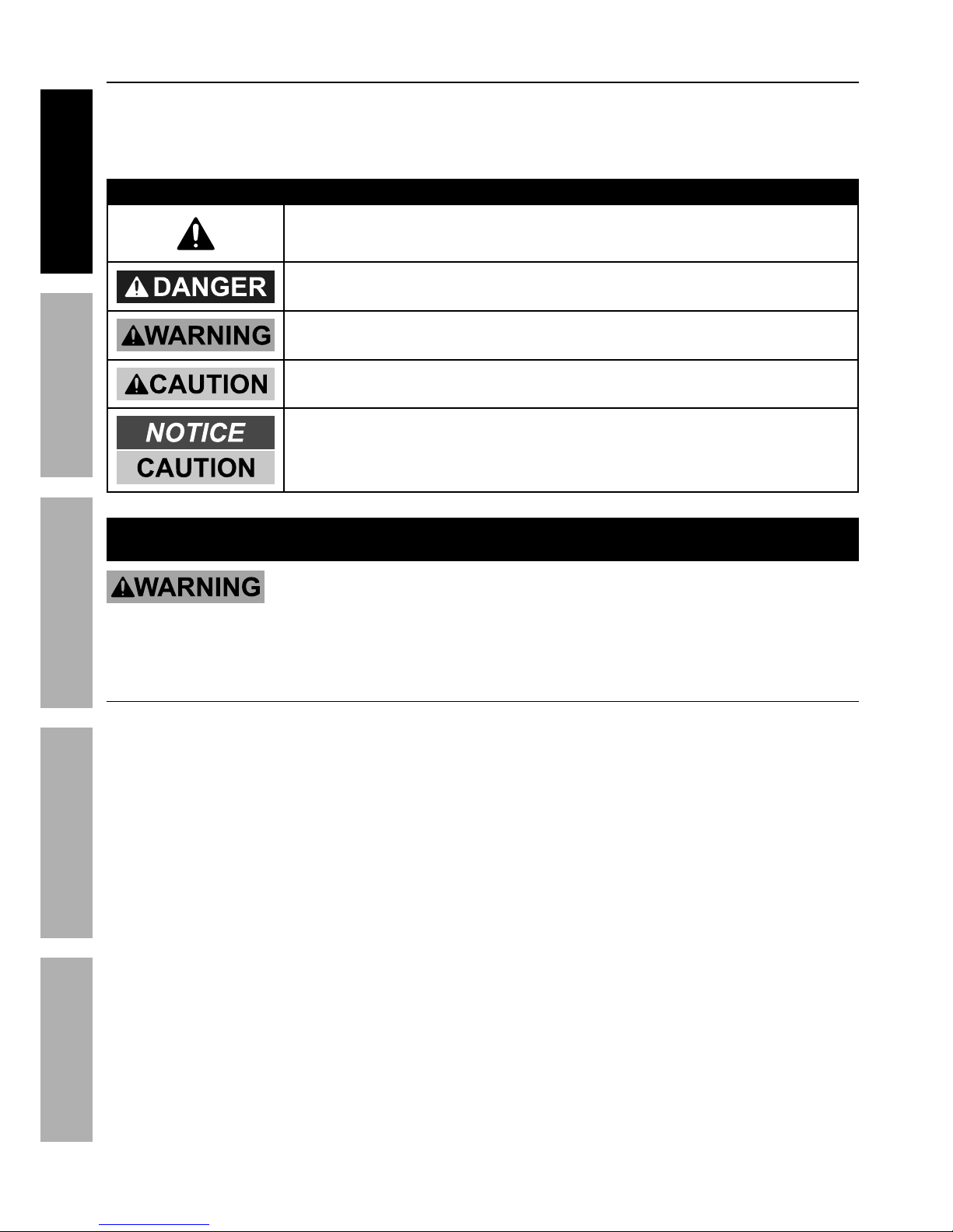
R@;ECET%?ODQVG?%@ES%S6<CECACVE?
This is the Safety alert symbol. It is used to alert you to potential
personal injury hazards. Obey all Safety messages that
follow this symbol to avoid possible injury or death.
Indicates a hazardous situation which, if not avoided,
will result in death or serious injury.
Indicates a hazardous situation which, if not avoided,
could result in death or serious injury.
Indicates a hazardous situation which, if not avoided,
could result in minor or moderate injury.
Addresses practices not related to personal injury.
CDUV;A@EA%?@<6AO%CE<V;D@ACVE
;*,9%,77%?,2*$>%),(8"83#%,89%"8#$('4$"&8#1%%
<,"7'(*%$&%2&77&)%$.*%),(8"83#%,89%"8#$('4$"&8#%5,>%(*#'7$%"8%*7*4$("4%#.&4WI%2"(*%,890&(%#*("&'#%"8='(>1%%%
?,X*%,77%),(8"83#%,89%"8#$('4$"&8#%2&(%2'$'(*%(*2*(*84*1
T*8*(,7%?,2*$>
U;VA6PA%>&'(#*72%,89%&$.*(#1%%;*,9%,89%'89*(#$,89%$."#%"82&(5,$"&81
1. Q*2&(*%'#*I%(*,9%,89%'89*(#$,89%
manufacturer′s instructions,
Material Safety Data Sheets (MSDS′s),
employer′s Safety practices, and ANSI Z49.1.
2. Y**/%&'$%&2%(*,4.%&2%4."79(*81%%%
Keep children and bystanders away while operating.
3. U7,4*%$.*%)*79*(%&8%,%#$,+7*%7&4,$"&8%+*2&(*%'#*1%%%
If it falls while plugged in, severe injury,
electric shock, or fire may result.
4. S&%8&$%&X*((*,4.1%%%
Y**/%/(&/*(%2&&$"83%,89%+,7,84*%,$%,77%$"5*#1
5. ?$,>%,7*($I%),$4.%).,$%>&'%,(*%9&"83%,89%'#*%
4&55&8%#*8#*%).*8%&/*(,$"83%,%)*79*(1%%
S&%8&$%'#*%,%)*79*(%)."7*%>&'%,(*%$"(*9%&(%'89*(%
$.*%"827'*84*%&2%9('3#I%,74&.&7%&(%5*9"4,$"&81
A moment of inattention while operating welders
may result in serious personal injury.
6. @X&"9%'8"8$*8$"&8,7%#$,($"831%%Make sure you are
prepared to begin work before turning on the Welder.
7. E*X*(%7*,X*%$.*%R*79*(%'8,$$*89*9%)."7*%
*8*(3"Z*91%Turn power off if you have to leave.
8. A.*%),(8"83#I%/(*4,'$"&8#I%,89%"8#$('4$"&8#%
9"#4'##*9%"8%$."#%"8#$('4$"&8%5,8',7%4,88&$%
4&X*(%,77%/&##"+7*%4&89"$"&8#%,89%#"$',$"&8#%
$.,$%5,>%&44'(1%%It must be understood by the
operator that common sense and caution are
factors which cannot be built into this product,
but must be supplied by the operator.
9. WARNING: This product, when used for welding,
plasma cutting, soldering, or similar applications,
produces chemicals known to the State of
California to cause cancer and birth defects
or other reproductive harm. (California Health
& Safety Code § 25249.5, et seq.)
10. WARNING: The cord of this product contains
lead and/or di (2-ethylhexyl) phthalate (DEHP),
chemicals known to the State of California
to cause cancer, and birth defects or other
reproductive harm. Wash hands after handling.
(California Health & Safety Code § 25249.5, et seq.)
Page 3
Page 3<&(%$*4.8"4,7%H'*#$"&8#I%/7*,#*%4,77%JKLLLKMLNKNMJL1Item 63618
?@<6AOD@CEA6E@EP6 Q@?CP%R6GSCETR6GSCET%ACU?
SETUP
?@<6AOD@CEA6E@EP6 Q@?CP%R6GSCETR6GSCET%ACU?
SETUP
<'5*%,89%T,#%?,2*$>
INHALATION HAZARD:%
R*79"83%,89%U7,#5,%P'$$"83%/(&9'4*%$&["4%2'5*#1
1. 6[/&#'(*%$&%)*79"83%&(%4'$$"83%*[.,'#$%
2'5*#%4,8%"84(*,#*%$.*%("#W%&2%9*X*7&/"83%
4*($,"8%4,84*(#I%#'4.%,#%4,84*(%&2%$.*%
7,(>8[%,89%7'83%4,84*(1 Also, some diseases
that may be linked to exposure to welding
or plasma cutting exhaust fumes are:
• Early onset of Parkinson’s Disease
• Heart disease
• Ulcers
• Damage to the reproductive organs
• Inflammation of the small intestine or stomach
• Kidney damage
• Respiratory diseases such as
emphysema, bronchitis, or pneumonia
Use natural or forced air ventilation and wear
a respirator approved by NIOSH to protect
against the fumes produced to reduce the
risk of developing the above illnesses.
2. S&%8&$%'#*%8*,(%9*3(*,#"83%&(%
/,"8$"83%&/*(,$"&8#1
3. Y**/%.*,9%&'$%&2%2'5*#1%%
Do not breathe exhaust fumes.
4. F#*%*8&'3.%X*8$"7,$"&8I%*[.,'#$%,$%,(4I%&(%
+&$.I%$&%W**/%2'5*#%,89%3,#*#%2(&5%+(*,$."83%
Z&8*%,89%3*8*(,7%,(*,1%%If engineering controls
are not feasible, use an approved respirator.
5. R&(W%"8%,%4&82"8*9%,(*,%&87>%"2%"$%
"#%)*77KX*8$"7,$*9I%&(%)."7*%)*,("83%
,8%,"(K#'//7"*9%(*#/"(,$&(1
6. B,X*%,%(*4&38"Z*9%#/*4",7"#$%"8%
C89'#$(",7%B>3"*8*%&(%68X"(&85*8$,7%?*(X"4*#%
4.*4W%$.*%&/*(,$"&8%,89%,"(%H',7"$>%
,89%5,W*%(*4&55*89,$"&8#%
2&(%$.*%#/*4"2"4%)*79"83%#"$',$"&81%%
Follow OSHA guidelines for
Permissible Exposure Limits (PEL’s) and
the American Conference of Governmental
Industrial Hygienists recommendations for
Threshold Limit Values (TLV’s) for fumes and gases.
@(4%;,>%?,2*$>
@;P%;@O?%4,8%"8='(*%*>*#%,89%+'(8%#W"81
1. R*,(%@E?CK,//(&X*9%)*79"83%*>*%/(&$*4$"&8%
2*,$'("83%,$%7*,#$%,%8'5+*(%JN%#.,9*%7*8#%(,$"831
2. R*,(%7*,$.*(%7*33"83#I%2"(*%(*#"#$,8$%#.&*#%
&(%+&&$#%9'("83%'#*1%%Do not wear pants with
cuffs, shirts with open pockets, or any clothing
that can catch and hold molten metal or sparks.
3. Y**/%47&$."83%2(**%&2%3(*,#*I%&"7I%
#&7X*8$#I%&(%,8>%27,55,+7*%#'+#$,84*#1%%
Wear dry, insulating gloves and protective clothing.
4. R*,(%,8%,//(&X*9%.*,9%4&X*("83%$&%/(&$*4$%
$.*%.*,9%,89%8*4W1%Use aprons, cape, sleeves,
shoulder covers, and bibs designed and
approved for welding and cutting procedures.
5. R*,(%,8%,//(&X*9%)*79"83%=,4W*$%&(%7&83%#7**X*#%
$&%/(&$*4$%2&(*,(5#%2(&5%(,9",$"&8%+'(8#1%
6. R.*8%)*79"8304'$$"83%&X*(.*,9%&(%"8%4&82"8*9%
#/,4*#I%)*,(%27,5*%(*#"#$,8$%*,(%/7'3#%&(%
*,(%5'22#%$&%W**/%#/,(W#%&'$%&2%*,(#1
Page 4
Page 4 <&(%$*4.8"4,7%H'*#$"&8#I%/7*,#*%4,77%JKLLLKMLNKNMJL1 Item 63618
?@<6AO D@CEA6E@EP6Q@?CP%R6GSCET R6GSCET%ACU?
SETUP
?@<6AO D@CEA6E@EP6Q@?CP%R6GSCET R6GSCET%ACU?
SETUP
67*4$("4,7%?,2*$>
6G6PA;CP%?BVPY%4,8%YCGG1
1. A'(8%&22I%9"#4&88*4$%/&)*(I%,89%
9"#4.,(3*%67*4$(&9*%$&%3(&'89%+*2&(*%#*$$"83%
9&)8%$&(4.067*4$(&9*%.&79*(%,89%+*2&(*%#*(X"4*1
2. S&%8&$%$&'4.%*8*(3"Z*9%*7*4$("4,7%/,($#1%%
Wear dry, insulating gloves. Do not touch Electrode
holder, Electrode, welding torch, or welding wire with
bare hand. Do not wear wet or damaged gloves.
3. P&88*4$%$&%3(&'89*9I%T<PCK/(&$*4$*9%
/&)*(%#'//7>%&87>1
4. S&%8&$%'#*%8*,(%),$*(%&(%9,5/%&+=*4$#1
5. U*&/7*%)"$.%/,4*5,W*(#%#.&'79%4&8#'7$%$.*"(%
physician(s) before use. Electromagnetic fields
in close proximity to heart pacemaker could cause
pacemaker interference or pacemaker failure.
6. S&%8&$%*[/&#*%)*79*(#%$&%(,"8%&(%)*$%4&89"$"&8#1%%%
Water entering a welder will increase
the risk of electric shock.
7. S&%8&$%,+'#*%$.*%4&(91%%E*X*(%'#*%$.*%4&(9%
2&(%4,((>"83I%/'77"83%&(%'8/7'33"83%$.*%)*79*(1%%
Y**/%4&(9%,),>%2(&5%.*,$I%&"7I%#.,(/%*93*#%
&(%5&X"83%/,($#1%%Damaged or entangled
cords increase the risk of electric shock.
8. S&%8&$%'#*%&'$9&&(#1
9. C8#'7,$*%>&'(#*72%2(&5%$.*%)&(W/"*4*%,89%
3(&'891%Use nonflammable, dry insulating
material if possible, or use dry rubber mats,
dry wood or plywood, or other dry insulating
material large enough to cover your full
area of contact with the work or ground.
<"(*%?,2*$>
@;P%@ES%?G@T%4,8%4,'#*%2"(*1
1. P7*,(%,),>%&(%/(&$*4$%27,55,+7*%&+=*4$#1%%%
Remove or make safe all combustible materials for a
radius of 35 feet (10 meters) around the work area.
Use a fire resistant material to cover
or block all open doorways, windows,
cracks, and other openings.
2. Y**/%@QPK$>/*%2"(*%*[$"83'"#.*(%8*,(%
)&(W%,(*,%,89%W8&)%.&)%$&%'#*%"$1
3. D,"8$,"8%,%#,2*%)&(W"83%*8X"(&85*8$1%%%
Keep the work area well lit.
Make sure there is adequate
surrounding workspace. Keep the work area free
of obstructions, grease, oil, trash, and other debris.
4. S&%8&$%&/*(,$*%)*79*(#%"8%,$5&#/.*(*#%
4&8$,"8"83%9,83*(&'#7>%(*,4$"X*%&(%
27,55,+7*%7"H'"9#I%3,#*#I%X,/&(#I%&(%9'#$1%%
Provide adequate ventilation in work areas
to prevent accumulation of such substances.
Welders create sparks which may ignite flammable
substances or make reactive fumes toxic.
5. C2%)&(W"83%&8%,%5*$,7%),77I%4*"7"83I%*$41I%
/(*X*8$%"38"$"&8%&2%4&5+'#$"+7*#%&8%$.*%
&$.*(%#"9*%+>%5&X"83%$.*%4&5+'#$"+7*#%$&%,%
#,2*%7&4,$"&81 If relocation of combustibles is
not possible, designate someone to serve as
a fire watch, equipped with a fire extinguisher,
during the cutting process and for at least one
half hour after the cutting is completed.
6. S&%8&$%)*79%&(%4'$%&8%5,$*(",7#%.,X"83%
,%4&5+'#$"+7*%4&,$"83%&(%4&5+'#$"+7*%
"8$*(8,7%#$('4$'(*I%,#%"8%),77#%&(%4*"7"83#I%)"$.&'$%
,8%,//(&X*9%5*$.&9%2&(%*7"5"8,$"83%$.*%.,Z,(91
7. S&%8&$%9"#/&#*%&2%.&$%#7,3%"8%4&8$,"8*(#%
.&79"83%4&5+'#$"+7*%5,$*(",7#1
8. @2$*(%)*79"83I%5,W*%,%$.&(&'3.%*[,5"8,$"&8%
2&(%*X"9*84*%&2%2"(*1%%Be aware that easily
visible smoke or flame may not be present
for some time after the fire has started.
9. S&%8&$%,//7>%.*,$%$&%,%4&8$,"8*(%$.,$%.,#%.*79%
,8%'8W8&)8%#'+#$,84*%&(%,%4&5+'#$"+7*%
5,$*(",7%).&#*%4&8$*8$#I%).*8%.*,$*9I%
4,8%/(&9'4*%27,55,+7*%&(%*[/7&#"X*%X,/&(#1%%
Clean and purge containers before applying heat.
Vent closed containers, including castings,
before preheating, welding, or cutting.
Page 5
Page 5<&(%$*4.8"4,7%H'*#$"&8#I%/7*,#*%4,77%JKLLLKMLNKNMJL1Item 63618
?@<6AOD@CEA6E@EP6 Q@?CP%R6GSCETR6GSCET%ACU?
SETUP
?@<6AOD@CEA6E@EP6 Q@?CP%R6GSCETR6GSCET%ACU?
SETUP
R*79*(%F#*%,89%P,(*
1. S&%8&$%'#*%$.*%)*79*(%"2%$.*%#)"$4.%9&*#%8&$%$'(8%
"$%&8%,89%&221%%Any welder that cannot be controlled
with the switch is dangerous and must be repaired.
2. S"#4&88*4$%$.*%/7'3%2(&5%$.*%/&)*(%
#&'(4*%+*2&(*%5,W"83%,8>%,9='#$5*8$#I%
4.,83"83%,44*##&("*#I%&(%#$&("83%)*79*(#1%%
Such preventive Safety measures reduce the
risk of starting the welder accidentally.
3. U(*X*8$%'8"8$*8$"&8,7%#$,($"831%
68#'(*%$.*%#)"$4.%"#%"8%$.*%&22K
/&#"$"&8%+*2&(*%4&88*4$"83%$&%/&)*(%
#&'(4*%&(%5&X"83%$.*%)*79*(1 Carrying
or energizing welders that have the
switch on invites accidents.
4. ?$&(*%"97*%)*79*(#%&'$%&2%$.*%(*,4.%&2%
4."79(*8%,89%9&%8&$%,77&)%/*(#&8#%'82,5"7",(%
)"$.%$.*%)*79*(%&(%$.*#*%"8#$('4$"&8#%$&%
&/*(,$*%$.*%)*79*(1%%Welders are dangerous
in the hands of untrained users.
5. F#*%$.*%)*79*(%,89%,44*##&("*#%"8%
,44&(9,84*%)"$.%$.*#*%"8#$('4$"&8#I%$,W"83%
"8$&%,44&'8$%$.*%)&(W"83%4&89"$"&8#%,89%
$.*%)&(W%$&%+*%/*(2&(5*91 Use of the welder
for operations different from those intended
could result in a hazardous situation.
6. S&%8&$%'#*%$.*%)*79*(%2&(%/"/*%$.,)"831
D,"8$*8,84*
1. D,"8$,"8%)*79*(#1%%P.*4W%2&(%5"#,7"385*8$%&(%
+"89"83%&2%5&X"83%/,($#I%+(*,W,3*%&2%/,($#%
,89%,8>%&$.*(%4&89"$"&8%$.,$%5,>%,22*4$%$.*%
)*79*(\#%&/*(,$"&81%%C2%9,5,3*9I%.,X*%$.*%
)*79*(%(*/,"(*9%+*2&(*%'#*1 Many accidents
are caused by poorly maintained welders.
2. B,X*%>&'(%)*79*(%#*(X"4*9%+>%,%H',7"2"*9%
(*/,"(%/*(#&8%'#"83%&87>%"9*8$"4,7%
(*/7,4*5*8$%/,($#1%%This will ensure that
the Safety of the welder is maintained.
3. D,"8$,"8%7,+*7#%,89%8,5*/7,$*#%&8%$.*%R*79*(1%%%
These carry important information.
If unreadable or missing, contact
Harbor Freight Tools for a replacement.
4. F8/7'3%+*2&(*%5,"8$*8,84*1%Unplug the Welder
from its electrical outlet before any inspection,
maintenance, or cleaning procedures.
T,#%?."*79*9%R*79"83%K%P>7"89*(%?,2*$>
P>7"89*(#%4,8%*[/7&9*%).*8%9,5,3*91
1. S&%8&$%)*79%&8%,%/(*##'("Z*9%&(%47&#*9%4>7"89*(1
2. S&%8&$%,77&)%,8%67*4$(&9*%.&79*(I%
67*4$(&9*I%)*79"83%$&(4.I%&(%)*79"83%
)"(*%$&%$&'4.%$.*%4>7"89*(1
3. Y**/%4>7"89*(#%,),>%2(&5%,8>%*7*4$("4,7%4"(4'"$#I%
"847'9"83%)*79"83%4"(4'"$#1
4. Y**/%/(&$*4$"X*%4,/%"8%/7,4*%&X*(%$.*%X,7X*%
*[4*/$%).*8%$.*%4>7"89*(%"#%"8%'#*1
5. F#*%&87>%4&((*4$%3,#%#."*79"83%*H'"/5*8$%
9*#"38*9%#/*4"2"4,77>%2&(%$.*%$>/*%&2%)*79"83%
>&'%)"77%9&1%%Maintain this equipment properly.
6. U(&$*4$%3,#%4>7"89*(#%2(&5%.*,$I%+*"83%#$('4WI%
/.>#"4,7%9,5,3*I%#7,3I%27,5*#I%#/,(W#I%,89%,(4#1
7. F#*%/(&/*(%/(&4*9'(*#%$&%5&X*%4>7"89*(#1
%?@!6%AB6?6%CE?A;FPACVE?1
Page 6

Page 6 <&(%$*4.8"4,7%H'*#$"&8#I%/7*,#*%4,77%JKLLLKMLNKNMJL1 Item 63618
?@<6AO D@CEA6E@EP6Q@?CP%R6GSCET R6GSCET%ACU?
SETUP
?@<6AO D@CEA6E@EP6Q@?CP%R6GSCET R6GSCET%ACU?
SETUP
T(&'89"83
AV%U;6!6EA%6G6PA;CP%?BVPY%@ES%S6@AB%%
<;VD%CEPV;;6PA%T;VFESCET%RC;6%PVEE6PACVE-%
P.*4W%)"$.%,%H',7"2"*9%*7*4$("4",8%"2%>&'%,(*%"8%9&'+$%,#%$&%).*$.*(%$.*%&'$7*$%"#%
/(&/*(7>%3(&'89*91%%%
S&%8&$%'#*%$.*%)*79*(%"2%$.*%/&)*(%4&(9%&(%/7'3%"#%9,5,3*91%%C2%9,5,3*9I%.,X*%"$%(*/,"(*9%+>%,%#*(X"4*%
2,4"7"$>%+*2&(*%'#*1%%C2%$.*%/7'3%)"77%8&$%2"$%$.*%&'$7*$I%.,X*%,%/(&/*(%&'$7*$%"8#$,77*9%+>%,%H',7"2"*9%*7*4$("4",8I%
9&%8&$%'#*%,9,/$*(%/7'3#1
1. The green wire inside the cord is connected to
the grounding system in the welder. The green
wire in the cord must be the only wire connected
to the welder’s grounding system and must never
be attached to an electrically “live” terminal.
Never leave the grounding wire disconnected
or modify the Power Cord Plug in any way.
2. Make sure the tool is connected to an outlet having
the same configuration as the plug. If the tool must
be reconnected for use on a different type of electric
circuit, the reconnection should be made by qualified
service personnel; and after reconnection, the tool
should comply with all local codes and ordinances.
B"3.%<(*H'*84>%T(&'89"83
1. The Welder has internal grounding, there
is no need to ground the Welder.
2. The metal work bench must be properly grounded
in accordance with all relevant electrical codes
and standards before operation. Have the work
bench grounded by a qualified electrician
if you are not qualified to do so.
3. To ground the work bench, connect a #12 AWG
grounding wire (not included) from the work
bench to a grounding rod (not included).
The grounding rod must be an earth-driven
copper or brass rod (electrode) which can
adequately ground the work bench.
4. Refer to local regulations for
ground source information.
B"3.%<(*H'*84>%;,9",$"&8
1. The operator of welding equipment that causes
harmful interference to radio services shall promptly
take appropriate measures to correct the problem.
2. If the operator of welding equipment is notified
by the FCC that operation of such equipment is
endangering the functioning of a radio navigation
or safety service, the operator shall immediately
cease operating the equipment. Operation may
be resumed on a temporary basis only for the
purpose of eliminating the harmful interference.
Operation may be resumed on a regular basis
only after the harmful interference has been
eliminated and approval from the FCC obtained.
3. When notified by the FCC that a particular
installation is causing harmful interference, the
operator or manufacturer shall arrange for an
engineer skilled in techniques of interference
measurement and control to make an investigation
to ensure that the harmful interference has
been eliminated. The Regional Director may
require the engineer making the investigation
to furnish proof of his or her qualifications.
6[$*8#"&8%P&(9#
S&%8&$%'#*%,8%*[$*8#"&8%4&(9%&8%$."#%)*79*(1
;*/7,4*5*8$%P&(9#
1. F#*%&87>%&8*%&2%$.*%#'//7"*9%/&)*(%4&(9#%2&(%
$."#%)*79*(%&(%,8%"9*8$"4,7%(*/7,4*5*8$%4&(91
2. S&%8&$%"8#$,77%,%$."88*(%&(%7&83*(%
4&(9%&8%$."#%)*79*(1
3. S&%8&$%/,$4.%4&(9#%&2%,8>%7*83$.%
$&3*$.*(%2&(%$."#%"$*51%%U,$4.*#%5,>%,77&)%
5&"#$'(*%$&%/*8*$(,$*%$.*%"8#'7,$"&8I%
(*#'7$"83%"8%*7*4$("4%#.&4W1
Page 7
Page 7<&(%$*4.8"4,7%H'*#$"&8#I%/7*,#*%4,77%JKLLLKMLNKNMJL1Item 63618
?@<6AOD@CEA6E@EP6 Q@?CP%R6GSCETR6GSCET%ACU?
SETUP
?@<6AOD@CEA6E@EP6 Q@?CP%R6GSCETR6GSCET%ACU?
SETUP
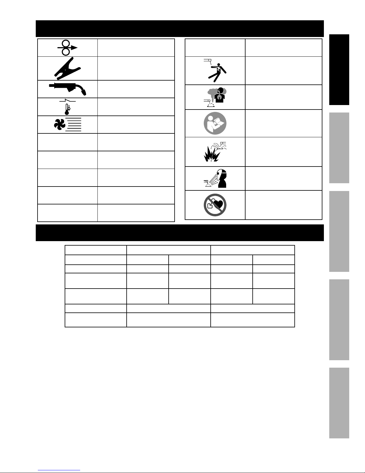
?>5+&7&3>
Wire Feed (Speed)
Workpiece Ground Cable
Torch Cable
Overheat Shutdown Indicator
Cooling Fan
!@P
Volts Alternating Current
@
Amperes
VP!
Open Circuit Voltage
Y!@
Kilovolt Amperes
(Volts / 1000 * Amperes)
CUD
Inches Per Minute
@RT
American Wire Gauge
Electric Shock Hazard.
Do not touch energized parts.
Inhalation Hazard.
Keep head out of fumes
and use proper ventilation.
Read manual before
setup and/or use.
Fire Hazard.
Keep flammable materials
away during welding. Spatter
can cause accidental fires.
Arc Ray Hazard.
Wear welding helmet with
properly rated filter lens.
Pacemaker Hazard.
Welding processes may
interfere with pacemakers.
Consult doctor before use.
?/*4"2"4,$"&8#
TIG Stick
Power Input 120VAC / 60Hz 240VAC / 60Hz 120VAC / 60Hz 240VAC / 60Hz
Current Input at Output 21.4A at 130A 14.7A at 165A 21.4A at 90A 22.4A at 165A
Welding Current Range 10A - 130A 10A - 165A 10A - 90A 10A - 165A
Rated Duty Cycles
25% @ 130A
100% @ 65A
30% @ 165A
100% @ 90A
25% @ 90A
100% @ 55A
30% @ 165A
100% @ 90A
Maximum OCV 103VDC 82VDC
Weldable Materials
Mild Steel, Stainless Steel,
Chrome Moly
Mild Steel, Stainless Steel
Page 8

Page 8 <&(%$*4.8"4,7%H'*#$"&8#I%/7*,#*%4,77%JKLLLKMLNKNMJL1 Item 63618
?@<6AO D@CEA6E@EP6Q@?CP%R6GSCET R6GSCET%ACU?
SETUP
?*$'/
% ;*,9%$.*%6EAC;6%CDUV;A@EA%?@<6AO%CE<V;D@ACVE%#*4$"&8%,$%$.*%+*3"88"83%&2%$."#%
5,8',7%"847'9"83%,77%$*[$%'89*(%#'+.*,9"83#%$.*(*"8%+*2&(*%#*$%'/%&(%'#*%&2%$."#%/(&9'4$1
AV%U;6!6EA%?6;CVF?%CE]F;O%<;VD%@PPCS6EA@G%VU6;@ACVE-%
A'(8%$.*%U&)*(%?)"$4.%&22%,89%'8/7'3%$.*%)*79*(%+*2&(*%#*$%'/1
Place the Welder on a level surface that can bear its weight near the work
area. Leave space around the Welder for proper air flow.
ACT%?*$'/
P&88*4$%P,+7*#
ACT%
A&(4.
T(&'89%
P7,5/
E*3,$"X*%
?&4W*$
<&&$%U*9,7%
?&4W*$
U&#"$"X*%
?&4W*$
<&&$%
U*9,7
1. Plug Ground Clamp cable into Positive Socket.
Twist clockwise all the way to lock in place.
2. Plug TIG Torch cable into Negative Socket.
Twist clockwise all the way to lock in place.
3. Plug Foot Pedal cable into Foot Pedal Socket.
Secure by turning collar clockwise until tight.
P&88*4$%?$(,/%
1. Thread end of Strap through slot on end of Welder.
2. Thread same end through bottom of buckle.
3. Repeat for other side.
4. Adjust Strap as necessary.
5. Pull on both ends of strap to make sure it is secure.
Page 9
Page 9<&(%$*4.8"4,7%H'*#$"&8#I%/7*,#*%4,77%JKLLLKMLNKNMJL1Item 63618
?@<6AOD@CEA6E@EP6 Q@?CP%R6GSCETR6GSCET%ACU?
SETUP
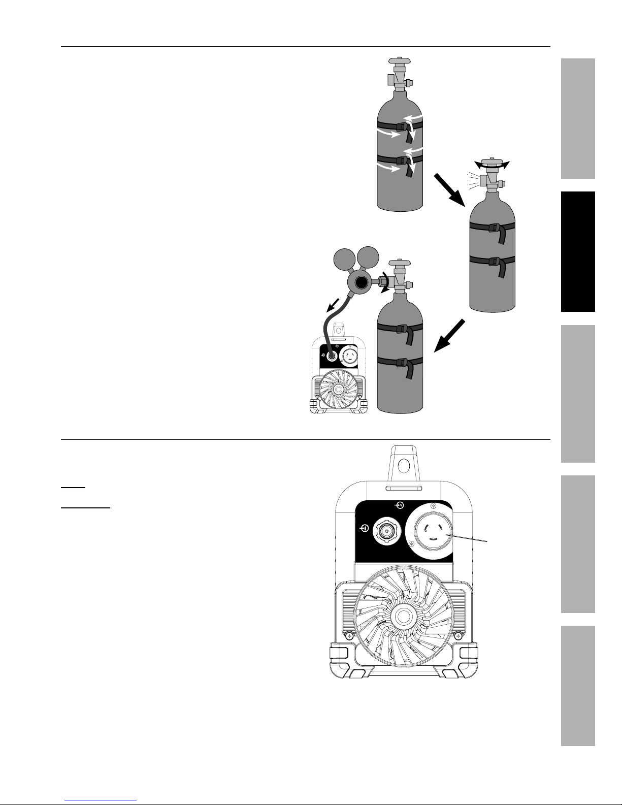
P&88*4$%?."*79"83%T,#
1. With assistance, place an 100% Argon cylinder
(not included) onto a cabinet or cart near the
Welder and secure the cylinder in place with
two straps (not included) to prevent tipping.
2. Remove the cylinder’s cap. Stand to the
side of the valve opening, then open the
valve briefly to blow dust and dirt from the
valve opening. Close the cylinder valve.
3. Close the Regulator’s valve by backing off
knob until it is loose, then thread Regulator
onto cylinder and wrench tighten connection.
4. Attach the Gas Hose (included) to the
Regulator’s Outlet and the Welder’s Gas Inlet.
Wrench-tighten both connections.
4
M
Q("*27>%&/*8%X,7X*%
$&%47*,8I%%
$.*8%47&#*%%
X,7X*1
^
J
Power Input
Gas Inlet
P&88*4$%U&)*(%P&(9
Plug either 120VAC or 240VAC cord
into Power Input Socket.
E&$*- Plug will only fit one way.
R@;ECET_ AV%U;6!6EA%?6;CVF?%CE]F;O%
<;VD%@PPCS6EA@G%VU6;@ACVE-%Do not
plug cord into wall outlet at this time.
Power Input
Gas Inlet
U&)*(%
C8/'$
Page 10

Page 10 <&(%$*4.8"4,7%H'*#$"&8#I%/7*,#*%4,77%JKLLLKMLNKNMJL1 Item 63618
?@<6AO D@CEA6E@EP6Q@?CP%R6GSCET R6GSCET%ACU?
SETUP
?.,(/*8%A'83#$*8%67*4$(&9*
To avoid Electrode contamination, dedicate a fine grit grinding wheel exclusively to Electrode grinding.
R@;ECET_ Some Electrodes may have
materials added to them that are hazardous to
breathe. Wear a respirator and ANSI-approved
Safety goggles when grinding an Electrode.
1. Shut off the welder and wait until Electrode
and Torch have cooled enough to handle.
2. Remove Back Cap. Pull Electrode from front
of Torch. (Pulling it from rear will damage
Collet and create burrs on Electrode).
3. If Electrode has dulled or been otherwise
contaminated, use pliers or a suitable tool to
grip the Electrode above the contaminated
section and snap off the end of the Electrode.
4. Lightly press Electrode tip
against the surface of
the grinding wheel at an angle.
Rotate Electrode tip until a
blunt point is formed.
E&$*- Grinding direction must be
parallel to length of Electrode.
5. The conical portion of the ideal
tip will be 2-1/2 times as long
as the Electrode diameter.
6. Re-insert Electrode into Collet with tip
protruding 1/8″-1/4″ beyond the Ceramic
Nozzle, then re-tighten the Back Cap.
@##*5+7*%ACT%A&(4.
1. Consult Settings Chart, on top of Welder, to
determine proper Tungsten Electrode size to be
used with thickness of material to be welded.
2. Match Collet and Collet Body sizes
to Tungsten Electrode size.
3. Thread Collet Body into the front of the Torch.
4. Make sure Ceramic Nozzle size is
appropriate for application.
5. Thread Ceramic Nozzle onto Collet Body.
6. Insert Collet into back of Torch and into Collet Body.
7. Insert tungsten Electrode into
Collet on front of Torch.
8. Lock Electrode in place with Back Cap.
Electrode should protrude 1/8″ to 1/4″
beyond the Ceramic Nozzle.
P&77*$%
Q&9>
P*(,5"4%
E&ZZ7*
P&77*$
Q,4W%P,/
C8#*($%$'83#$*8%
67*4$(&9*%.*(*1
T("89"83%
R.**7
67*4$(&9*
Page 11

Page 11<&(%$*4.8"4,7%H'*#$"&8#I%/7*,#*%4,77%JKLLLKMLNKNMJL1Item 63618
?@<6AOD@CEA6E@EP6 Q@?CP%R6GSCETR6GSCET%ACU?
SETUP
?$"4W%?*$'/
P&88*4$%P,+7*#
67*4$(&9*%
B&79*(
T(&'89%
P7,5/
U&#"$"X*%
?&4W*$
E*3,$"X*%
?&4W*$
1. Plug Ground Clamp cable into Negative Socket.
Twist clockwise all the way to lock in place.
2. Plug Electrode Holder cable into Positive Socket.
Twist clockwise all the way to lock in place.
P&88*4$%U&)*(%P&(9
Plug either 120VAC or 240VAC cord
into Power Input Socket.
E&$*- Plug will only fit one way.
R@;ECET_ AV%U;6!6EA%?6;CVF?%CE]F;O%
<;VD%@PPCS6EA@G%VU6;@ACVE-%Do not
plug cord into wall outlet at this time.
Power Input
Gas Inlet
U&)*(%
C8/'$
Page 12

Page 12 <&(%$*4.8"4,7%H'*#$"&8#I%/7*,#*%4,77%JKLLLKMLNKNMJL1 Item 63618
?@<6AO D@CEA6E@EP6Q@?CP%R6GSCET R6GSCET%ACU?
SETUP
Q,#"4%R*79"83
% ;*,9%$.*%6EAC;6%CDUV;A@EA%?@<6AO%CE<V;D@ACVE%#*4$"&8%,$%$.*%+*3"88"83%&2%$."#%
5,8',7%"847'9"83%,77%$*[$%'89*(%#'+.*,9"83#%$.*(*"8%+*2&(*%#*$%'/%&(%'#*%&2%$."#%/(&9'4$1
%
AV%U;6!6EA%?6;CVF?%CE]F;O-%
U(&$*4$"X*%3*,(%5'#$%+*%)&(8%).*8%'#"83%$.*%R*79*(`%5"8"5'5%#.,9*%8'5+*(%JN%2'77%2,4*%#."*79%
(or welding mask), ear protection, welding gloves, sleeves and apron, NIOSH-approved respirator, and fire
(*#"#$,8$%)&(W%47&$.*#%)"$.&'$%/&4W*$#%#.&'79%+*%)&(8%).*8%)*79"831%%%
G"3.$%2(&5%$.*%,(4%4,8%4,'#*%/*(5,8*8$%9,5,3*%$&%$.*%*>*#%,89%#W"81%%
S&%8&$%+(*,$.*%,(4%2'5*#1
• DC TIG Welding is used to weld mild
steel and stainless steel using a TIG Rod
and shielding gas. (To weld aluminum,
an AC TIG Welder must be used.)
• Stick Welding is used to weld mild
steel and stainless steel using a
Stick Electrode without shielding gas.
Good welding takes a degree of skill and experience.
Practice a few sample welds on scrap before
welding your first project. Additional practice
periods are recommended whenever you weld:
• a different thickness of material
• a different type of material
• a different type of connection
• using a different process
D,W*%/(,4$"4*%)*79#%&8%/"*4*#%&2%#4(,/%$&%/(,4$"4*%
$*4.8"H'*%+*2&(*%)*79"83%,8>$."83%&2%X,7'*1
AV%U;6!6EA%?6;CVF?%CE]F;OI%%
<C;6%@ES%QF;E?-%
Y**/%)*79"83%$"/%47*,(%&2%3(&'89*9%
&+=*4$#%).*8*X*(%'8"$%"#%/7'33*9%
"8%,89%$'(8*9%&81
U&)*(%
V8
a
U(,4$"4*%>&'(%)*79"83%
$*4.8"H'*%&8%#4(,/%
/"*4*#%+*2&(*%)*79"83%
,8>$."83%&2%X,7'*1
Page 13

Page 13<&(%$*4.8"4,7%H'*#$"&8#I%/7*,#*%4,77%JKLLLKMLNKNMJL1Item 63618
?@<6AOD@CEA6E@EP6 Q@?CP%R6GSCETR6GSCET%ACU?
SETUP
P&8$(&7#
!&7$,3*%
C8/'$0
A.*(5,7%
VX*(7&,9%
C89"4,$&(
U&)*(%
C89"4,$&(
U(&4*##%
?*7*4$%
Q'$$&8
U&)*(%
?)"$4.
@5/*(,3*%
Y8&+
?*$$"83#%P.,($
(on top of Welder)
U&)*(%C89"4,$&(-
Lights when power is on.
!&7$,3*%C8/'$0A.*(5,7%VX*(7&,9%C89"4,$&(-
Lights when input voltage is outside the Welder’s
specifications or duty cycle has been exceeded.
@5/*(,3*%Y8&+-%
Controls output amperage.
U(&4*##%?*7*4$%Q'$$&8-%
Push to cycle through processes.
Page 14

Page 14 <&(%$*4.8"4,7%H'*#$"&8#I%/7*,#*%4,77%JKLLLKMLNKNMJL1 Item 63618
?@<6AO D@CEA6E@EP6Q@?CP%R6GSCET R6GSCET%ACU?
SETUP
?*$$"83%'/%$.*%R*79
47,5/#
)&(W/"*4*#
P.,52*(%$."4W%)&(W/"*4*#1
P7*,8%#'(2,4*#%
$&%+,(*%5*$,71
D,W*%/(,4$"4*%)*79#%&8%/"*4*#%
&2%#4(,/%$.*%#,5*%$."4W8*##%
,#%>&'(%"8$*89*9%)&(W/"*4*%
$&%/(,4$"4*%$*4.8"H'*%+*2&(*%
)*79"83%,8>$."83%&2%X,7'*1
%
1. Clean the weld surfaces thoroughly with
a wire brush or angle grinder; there must
be no rust, paint, oil, or other materials on
the weld surfaces, only bare metal.
2. Use clamps (not included) to hold the workpieces
in position so that you can concentrate on
proper welding technique. The distance
(if any) between the two workpieces must be
controlled properly to allow the weld to hold
both sides securely while allowing the weld
to penetrate fully into the joint. The edges of
thicker workpieces may need to be chamfered
(or beveled) to allow proper weld penetration.
NOTICE: When welding equipment on a vehicle,
disconnect the vehicle battery power from both the
positive connection and the ground before welding.
This prevents damage to some vehicle electrical
systems and electronics due to the high voltage
and high frequency bursts common in welding.
T(&'89%R&(W/"*4*
Attach Ground Clamp to bare metal on the
workpiece near the weld area, or to metal work
bench where the workpiece is clamped.
R&(W/"*4*
T(&'89%
P7,5/
P7*,8%
#'(2,4*%$&%
+,(*%5*$,71
Page 15

Page 15<&(%$*4.8"4,7%H'*#$"&8#I%/7*,#*%4,77%JKLLLKMLNKNMJL1Item 63618
?@<6AOD@CEA6E@EP6 Q@?CP%R6GSCETR6GSCET%ACU? ?6AFU
Duty Cycle (Duration of Use)
@X&"9%9,5,3*%$&%$.*%R*79*(%+>%8&$%)*79"83%2&(%
5&(*%$.,8%$.*%/(*#4("+*9%9'$>%4>47*%$"5*1 The Duty
Cycle defines the number of minutes, within a 10 minute
period, during which a given welding process can
produce a particular welding current without overheating.
For example, a 30% duty cycle at 165 A welding
current must be allowed to rest for at least 7 minutes
after every 3 minutes of continuous welding.
Failure to carefully observe duty cycle limitations
can easily over-stress a welder’s power generation
system contributing to premature welder failure.
This welder has an internal thermal protection
system to help prevent this sort of over-stress.
When the Welder overheats, it automatically shuts
down and the Overload Indicator lights. The welder
automatically returns to service after cooling
off. Rest the Tig Torch or Electrode Holder on an
electrically non-conductive, heat-proof surface, such
as a concrete slab, well clear of the ground clamp.
@77&)%$.*%R*79*(%$&%4&&7%)"$.%$.*%U&)*(%?)"$4.%&8I%
#&%$.,$%$.*%"8$*(8,7%<,8%)"77%.*7/%4&&7%$.*%)*79*(1
When the Overload Indicator is no longer lit and the
Welder can be used again, use shorter welding periods
and longer rest periods to prevent needless wear.
240VAC
30% Use at 165 A
<&(%JN%P&8$"8'&'#%D"8'$*#
100% Continuous Use at 90 A
M
D"8'$*#%
R*79"83
b%
D"8'$*#%
;*#$"83
J^N!@P
25% Use at 90 A
<&(%JN%P&8$"8'&'#%D"8'$*#
100% Continuous Use at 55 A
^KJ0^
D"8'$*#%
R*79"83
bKJ0^%
D"8'$*#%
;*#$"83
?$"4W%;,$*9%S'$>%P>47*#
240VAC
30% Use at 165 A
<&(%JN%P&8$"8'&'#%D"8'$*#
100% Continuous Use at 90 A
M
D"8'$*#%
R*79"83
b%
D"8'$*#%
;*#$"83
J^N!@P
25% Use at 130 A
<&(%JN%P&8$"8'&'#%D"8'$*#
100% Continuous Use at 65 A
^KJ0^
D"8'$*#%
R*79"83
bKJ0^%
D"8'$*#%
;*#$"83
ACT%;,$*9%S'$>%P>47*#
Page 16

Page 16 <&(%$*4.8"4,7%H'*#$"&8#I%/7*,#*%4,77%JKLLLKMLNKNMJL1 Item 63618
?@<6AO D@CEA6E@EP6Q@?CP%R6GSCET R6GSCET%ACU?
SETUP
ACT%R*79"83
AV%U;6!6EA%?6;CVF?%CE]F;O%@ES%S6@AB-%%%
S&%8&$%)*79%)"$.&'$%T(&'89"83%P7,5/1%%
R.*8%$.*%&/*(,$&(%"#%8&$%.&79"83%$.*%A&(4.I%"$%5'#$%+*%#"$$"83%&8%,%8&84&89'4$"X*I%8&827,55,+7*%#'(2,4*1%
V87>%.&79%ACT%;&9%)"$.%,8%*7*4$("4,77>%"8#'7,$*9%)*79"83%37&X*1
%%%
AV%U;6!6EA%S6@AB%<;VD%@?UBOcC@ACVE-%
S&%8&$%&/*8%3,#%)"$.&'$%/(&/*(%X*8$"7,$"&81%%<"[%3,#%7*,W#%"55*9",$*7>1 Shielding gas can displace
air and cause rapid loss of consciousness and death. ?."*79"83%3,#%)"$.&'$%4,(+&8%9"&["9*%4,8%+*%
*X*8%5&(*%.,Z,(9&'#%+*4,'#*%,#/.>[",$"&8%4,8%#$,($%)"$.&'$%2**7"83%#.&($8*##%&2%+(*,$.1
EVACP6-% TIG welding is a complicated process,
requiring experience and skill to achieve
successful results. Training beyond the scope of
this manual is required to TIG weld properly.
1. Open gas cylinder’s valve all the way.
2. Set Flow Gauge to SCFH value indicated
on Settings Chart on top of Welder.
3. Turn the Power Switch to the OFF position, then
plug the Welder into a properly grounded, GFCI
protected, 120 VAC (20 amp rated) outlet or 240V
outlet.
The circuit must be equipped with delayed
action-type circuit breaker or fuses.
4. Set TIG Torch down on nonconductive,
nonflammable surface away from
any grounded objects.
5. Turn the Power Switch ON.
6. Set amperage according to Settings Chart on top of
Welder.
Set to high end of amperage range.
For example: Range is 80-100A,
set amperage to 100A.
EVA6- Settings are approximate. Adjust as necessary.
CDUV;A@EA- If Welder is plugged into 120V outlet, set
amperage according to settings on white band.
If Welder is plugged into 240V outlet, set amperage
according to settings on orange band.
7. ?*7*4$%U(&4*##- Press Process Select
Button until desired process(es) light up:
U(&4*##%
?*7*4$%
Q'$$&8
J^N!%
@5/*(,3*%
?*$$"83#%
(white)
240V
@5/*(,3*%
?*$$"83#
(orange)
ACT%B<%
B"3.%<(*H'*84>%?$,($%)"$.%E&(5,7%R*79"83%
Usual way to initiate arc and weld.
and ACT%B<%,89%ACT%UFG?6%%
B"3.%<(*H'*84>%?$,($%)"$.%U'7#*%R*79"83%
Usual way to initiate arc.
Pulse welding reduces heat input to minimize
distortion and allows for faster travel speeds.
R@;ECET_ D*$,7%)&(W%+*84.%5'#$%+*%3(&'89*9%
).*8%'#"83%B"3.%<(*H'*84>%?$,($%d#**%B"3.%
Frequency Grounding on page 6).
EVACP6- When welding close to sensitive electronics
or on vehicles, use Lift Start instead of High Frequency.
ACT%GC<A
G"2$%?$,($ )"$.%E&(5,7%R*79"83
Use when High Frequency Start cannot be used.
and ACT%GC<A%,89%ACT%UFG?6
G"2$%?$,($%)"$.%U'7#* R*79"83
Use when High Frequency Start cannot be used.
Pulse welding reduces heat input to minimize
distortion and allows for faster travel speeds.
%%?ACPY%K%T&%$&%?$"4W%R*79"83%&8%/,3*%JL1
Page 17

Page 17<&(%$*4.8"4,7%H'*#$"&8#I%/7*,#*%4,77%JKLLLKMLNKNMJL1Item 63618
?@<6AOD@CEA6E@EP6 Q@?CP%R6GSCETR6GSCET%ACU?
SETUP
R@;ECET_%%AV%U;6!6EA%?6;CVF?%CE]F;O-%%
U(&$*4$"X*%3*,(%5'#$%+*%)&(8%).*8%'#"83%$.*%
R*79*(`%5"8"5'5%#.,9*%8'5+*(%JN%2'77%2,4*%#."*79%
(or welding mask), ear protection, welding gloves,
#7**X*#%,89%,/(&8I%ECV?BK,//(&X*9%(*#/"(,$&(I%
,89%2"(*%(*#"#$,8$%)&(W%47&$.*#%)"$.&'$%/&4W*$#%
#.&'79%+*%)&(8%).*8%)*79"831%%G"3.$%2(&5%$.*%
,(4%4,8%4,'#*%/*(5,8*8$%9,5,3*%$&%$.*%*>*#%
,89%#W"81%%S&%8&$%+(*,$.*%,(4%2'5*#1
After practice welding on scrap, stop,
and check your progress. Perform
Strike Test according to ?$("W*%A*#$%&8%
/,3*%^N1 After making any necessary
adjustments, continue to weld while
carefully following the DUTY CYCLE
guidelines as explained on page 14.
8. Hold TIG Torch in one gloved hand and
TIG Rod in other gloved hand.
9. Specific Welding Techniques:
ACT%B<%?$,($%
• Hold Torch ,),>%2(&5%$.*%)&(W/"*4*
the same distance as 1 to 1.5 times the
diameter of the Tungsten Electrode.
E&$*- To prevent Tungsten Electrode contamination,
do not touch Torch to workpiece before arc initiates.
• Press Foot Pedal down slowly until arc
initiates. Then, press Foot Pedal down all
the way to reach maximum amperage. Let
up on Foot Pedal to lower amperage.
ACT%GC<A%?$,($%
• Touch Tungsten Electrode to workpiece.
• Press Foot Pedal down 1 - 2 seconds.
Then, lift Electrode off workpiece the same
distance as 1 to 1.5 times the diameter
of the Electrode, to initiate the arc.
• Press Foot Pedal down all the way to
reach maximum amperage. Let up on
Foot Pedal to lower amperage.
ACT%UFG?6%R*79"83
• After arc is initiated, Welder will
pulse between Peak Amperage and
Background Current at a rate of 2 PPS.
• Peak Amperage Time is 50%.
Background Current is 30% of
Peak Amperage Current.
EVA6- Maintain a constant distance between the
Tungsten Electrode and the workpiece: between
1 and 1.5 times the diameter of the Electrode.
10. When welding puddle is hot enough, tilt torch
backward about 10-15 degrees from vertical and
move it back slightly. Add TIG Rod material as
needed to the front end of the weld puddle.
11. Alternate between pushing the torch/weld
puddle and adding the TIG Rod material.
EVA6- Back the TIG Rod off each time the Electrode
is advanced, but do not remove it from the gas shield.
This prevents oxidation from contaminating the weld.
12. When finished welding, release the Foot Pedal, but
keep Torch on weld puddle until gas flow ends.
13. Set TIG Torch down on nonconductive,
nonflammable surface away from
any grounded objects.
14. Turn the Amperage Knob to the lowest
setting, then turn the Power Switch off.
15. To prevent accidents, after use:
• Allow Welder to cool down.
• Unplug Welder’s power cord from outlet.
• Remove Ground Clamp from workpiece or table.
• Disconnect TIG Torch, Ground
and Food Pedal Cables.
• Close gas cylinder’s valve securely,
remove regulator and replace cap.
• Disconnect Gas Hose from Welder.
• Store and secure gas cylinder.
• Clean, then store Welder and its accessories
indoors out of children’s reach.
Page 18

Page 18 <&(%$*4.8"4,7%H'*#$"&8#I%/7*,#*%4,77%JKLLLKMLNKNMJL1 Item 63618
?@<6AO D@CEA6E@EP6Q@?CP%R6GSCET R6GSCET%ACU?
SETUP
?$"4W%R*79"83
AV%U;6!6EA%?6;CVF?%CE]F;O%@ES%S6@AB-%%%
S&%8&$%)*79%)"$.&'$%T(&'89"83%P7,5/1%%
R.*8%$.*%&/*(,$&(%"#%8&$%.&79"83%$.*%67*4$(&9*%B&79*(I%"$%5'#$%+*%
#"$$"83%&8%,%8&84&89'4$"X*I%8&827,55,+7*%#'(2,4*1%%
1. Turn the Power Switch to the OFF position, then
plug the Welder into a properly grounded, GFCI
protected, 120 VAC (20 amp rated) outlet or 240V
outlet.
The circuit must be equipped with delayed
action-type circuit breaker or fuses.
2. Set Electrode Holder down on
nonconductive, nonflammable surface
away from any grounded objects.
3. Turn the Power Switch ON.
R@;ECET_ R.*8%?$"4W%"#%#*7*4$*9I%R*79*(%
"#%*8*(3"Z*9I%B&$%?$,($%"#%,4$"X,$*9%,89%
V/*8%P"(4'"$%!&7$,3*%"#%/(*#*8$1
4. ?*7*4$%U(&4*##- Press Process Select
Button until %%?ACPY%process lights up.
U(&4*##%
?*7*4$%
Q'$$&8
J^N!%
@5/*(,3*%
?*$$"83#%
(white)
240V
@5/*(,3*%
?*$$"83#
(orange)
5. Set Amperage according to Stick Settings Chart.
EVA6- Settings are approximate. Adjust as necessary.
CDUV;A@EA- If Welder is plugged into 120V outlet, set
amperage according to settings on white band.
If Welder is plugged into 240V outlet, set amperage
according to settings on orange band.
?$"4W%?*$$"83#%P.,($%
67*4$(&9*%
A>/*
67*4$(&9*%
S",5*$*(
@5/*(,3*%
;,83*
eNJN%SP
eNJJ%@P0SP
M0M^f 40-70
J0Lf bgKJMN
g0M^f 90-175
M0Jef 140-225
eNJM%@P0SP
J0Jef 25-40
M0M^f 40-90
J0Lf bgKJ^g
g0M^f JNgKJbg
7014 AC/DC
M0M^f bgKJJN
J0Lf JNgKJeN
g0M^f JgNK^NN
bNJL%@P0SP
M0M^f bNKJJN
J0Lf 90-160
g0M^f JMNK^JN
7024 AC/DC
M0M^f 100-145
J0Lf JJNKJbg
Page 19

Page 19<&(%$*4.8"4,7%H'*#$"&8#I%/7*,#*%4,77%JKLLLKMLNKNMJL1Item 63618
?@<6AOD@CEA6E@EP6 Q@?CP%R6GSCETR6GSCET%ACU?
SETUP
R@;ECET_%%AV%U;6!6EA%?6;CVF?%CE]F;O-%%
U(&$*4$"X*%3*,(%5'#$%+*%)&(8%).*8%'#"83%$.*%
R*79*(`%5"8"5'5%#.,9*%8'5+*(%JN%2'77%2,4*%#."*79%
(or welding mask), ear protection, welding gloves,
#7**X*#%,89%,/(&8I%ECV?BK,//(&X*9%(*#/"(,$&(I%
,89%2"(*%(*#"#$,8$%)&(W%47&$.*#%)"$.&'$%/&4W*$#%
#.&'79%+*%)&(8%).*8%)*79"831%%G"3.$%2(&5%$.*%
,(4%4,8%4,'#*%/*(5,8*8$%9,5,3*%$&%$.*%*>*#%
,89%#W"81%%S&%8&$%+(*,$.*%,(4%2'5*#1
After practice welding on scrap, stop,
and check your progress. Perform
Strike Test, then clean and compare your
weld’s appearance with the diagrams and
descriptions in the R*79"83%A"/# section
starting on the next page. After making any
necessary adjustments, continue to weld
while carefully following the DUTY CYCLE
guidelines as explained on page 14.
6. Place the bare metal end of the Stick
Electrode (sold separately) inside the
jaws of the Electrode Holder.
7. Stroke the workpiece lightly to initiate the arc.
Tips for igniting the arc:
a. Tap the surface with the Electrode.
b. Stroke the surface with the Electrode.
c. Strike the surface like a match with the Electrode.
8. After the arc initiates:
a. Lift the Electrode off workpiece the same
distance as the diameter of the bare metal end.
b. Tilt Electrode back 10 to 20 degrees.
c. Drag Electrode to the back end of the weld
puddle to deposit material as needed.
9. When finished welding; lift the Electrode from
the workpiece, then set Electrode Holder
down on nonconductive, nonflammable
surface away from any grounded objects.
10. Turn the Power Switch off.
11. To prevent accidents, after use:
• Allow Welder to cool down.
• Unplug Welder’s power cord from outlet.
• Remove Ground Clamp.
• Disconnect TIG Torch and Ground Cables.
• Close gas cylinder’s valve
securely and replace cap.
• Disconnect Gas Hose from Welder.
Store and secure gas cylinder.
• Clean, then store Welder and its accessories
indoors out of children’s reach.
Page 20

Page 20 <&(%$*4.8"4,7%H'*#$"&8#I%/7*,#*%4,77%JKLLLKMLNKNMJL1 Item 63618
?@<6AO D@CEA6E@EP6Q@?CP%R6GSCET R6GSCET%ACU?
SETUP
R*79"83%A"/#
A good way to test welding technique is to examine a weld’s appearance after it has
cooled and the slag has been removed (for Stick welds). Then, better welding can be
learned by adjusting your weld technique to remedy any problems found.
NOTICE: TIG welding is a complicated process, requiring experience and skill to achieve successful
results. Training beyond the scope of this manual is required to TIG weld properly.
@2$*(%/(,4$"4*%)*79"83%,%4&'/7*%
&2%)*79"83%+*,9#I%?AVU%,89%
*[,5"8*%>&'(%)*79%'#"83%
$.*%2&77&)"83%3'"9*7"8*#1
?$("W*%A*#$
@%$*#$%)*79%&8%,%UC6P6%V<%?P;@U%4,8%+*%
$*#$*9%+>%'#"83%$.*%2&77&)"83%/(&4*9'(*1
R6@;%@E?CK@UU;V!6S%?@<6AO%TVTTG6?%
SF;CET%ABC?%U;VP6SF;61
R@;ECET_ A."#%$*#$%RCGG%9,5,3*%$.*%)*79%"$%"#%
/*(2&(5*9%&81%%A."#%$*#$%"#%VEGO%,8%"89"4,$&(%&2%)*79%
$*4.8"H'*%,89%"#%8&$%"8$*89*9%$&%$*#$%)&(W"83%)*79#1
1. After two scraps have been welded together and the
weld has cooled, clamp one side in a sturdy vise.
2. Stay clear from underneath while you strike
the opposite side with a heavy hammer,
preferably a dead-blow hammer.
3. A TVVS%R6GS will deform but not break, as shown
on top.
A UVV;%R6GS will be brittle and snap
at the weld, as shown on bottom.
!"#*
?P;@U%
R&(W/"*4*
TVVS%R6GS%%
Q*89#%,89%"#%E&$%Q("$$7*
S*,9KQ7&)%B,55*(
!"#*
?P;@U%
R&(W/"*4*
UVV;%R6GS%%
?8,/#%&(%P(,4W#
S*,9KQ7&)%B,55*(
P7*,8"83%?$"4W%R*79
AV%U;6!6EA%?6;CVF?%CE]F;O-%
R*,(%@E?CK,//(&X*9%#,2*$>%3&337*#%
,89%/(&$*4$"X*%)*,(%).*8%47*,8"83%,%
)*791%%
?/,(W#%&(%4."/#%5,>%27>%).*8%47*,8"831
1. A weld from Stick welding will be covered
by slag. Use a chipping hammer to knock
this off. Q*%4,(*2'7%8&$%$&%9,5,3*%
$.*%)*79%&(%+,#*%5,$*(",71
2. Use a wire brush to further clean the weld
or use an angle grinder (sold separately) to
shape the weld.
P."//"83%
B,55*(
R"(*%Q('#.
Page 21

Page 21<&(%$*4.8"4,7%H'*#$"&8#I%/7*,#*%4,77%JKLLLKMLNKNMJL1Item 63618
?@<6AOD@CEA6E@EP6 Q@?CP%R6GSCETR6GSCET%ACU?
SETUP
?$"4W%R*79%S",38&#"#%K%R&(W/"*4*%B*,$%P&8$(&7%0%R*79%U*8*$(,$"&8
6cP6??%U6E6A;@ACVE%V;%
QF;EKAB;VFTB
U;VU6;%U6E6A;@ACVECE@S6hF@A6%U6E6A;@ACVE
E&$%.&$%*8&'3. A&&%.&$C9*,7%.*,$
B&)%$&%"84(*,#*%)&(W/"*4*%.*,$%%
,89%"84(*,#*%/*8*$(,$"&8-%%
d$&%)*79%ABCPY6; workpieces properly)
a. Increase current. b. Weld more slowly.
B&)%$&%(*9'4*%)&(W/"*4*%.*,$%%
,89%7"5"$%/*8*$(,$"&8-%%
d$&%)*79%ABCEE6; workpieces properly)
a. Decrease current. b. Weld more quickly.
?$"4W%R*79%6[,5/7*%S",3(,5#
PG6@E%R6GS?%<C;?A_
?$"4W%)*79#%)"77%.,X*%,%4&,$%&2%#7,3%&X*(%$.*5%'8$"7%47*,8*91
T&&9%
R*79
P'((*8$%%
A&&%G&)%
AV%PV;;6PA- %
Increase the
current
AV%PV;;6PA- %
Decrease
the current
P'((*8$%%
A&&%B"3.
AV%PV;;6PA-
Weld slower
R*79%?/**9%
A&&%<,#$
AV%PV;;6PA-
Weld faster
R*79%?/**9%
A&&%?7&)
@(4%G*83$.%%
A&&%?.&($%
AV%PV;;6PA-
Increase
distance
@(4%G*83$.%%
A&&%G&83%
AV%PV;;6PA-
Decrease
distance
Page 22

Page 22 <&(%$*4.8"4,7%H'*#$"&8#I%/7*,#*%4,77%JKLLLKMLNKNMJL1 Item 63618
?@<6AO D@CEA6E@EP6Q@?CP%R6GSCET R6GSCET%ACU?
SETUP
Stick Weld Penetration (Workpiece Heat Control)
6cP6??%U6E6A;@ACVE%V;%
QF;EKAB;VFTB
R*79%9(&&/#%&8%$&/%,89%
'89*(8*,$.%&(%2,77#%$.(&'3.%
*8$"(*7>I%5,W"83%,%.&7*1
U;VU6;%U6E6A;@ACVE
R*79%"#%X"#"+7*%'89*(8*,$.%,89%
+'73*#%#7"3.$7>%&8%$&/1
CE@S6hF@A6%U6E6A;@ACVE
R*79%9&*#%8&$%4&8$,4$%$.*%=&"8$%
2'77>I%='#$%&8%$.*%#'(2,4*1
PROFILE VIEWS
UV??CQG6%P@F?6?%@ES%?VGFACVE?%<V;%
1. R&(W/"*4*%&X*(.*,$"83-%
Reduce current.
2. R*79"83%#/**9%$&&%#7&)-
Increase welding speed and ensure
that welding speed is kept steady.
UV??CQG6%P@F?6?%@ES%?VGFACVE?%<V;
1. C84&((*4$%)*79"83%$*4.8"H'*-
Keep arc on leading edge of weld puddle.
Hold torch at proper angles.
2. C8#'22"4"*8$%)*79%.*,$-%
Slow down so fill material has time to melt
into the weld location. Increase current.
3. R&(W/"*4*#%$&&%$."4W047&#*-
Bevel thick workpieces, allow slight
gap, and weld in several passes.
4. C8#'22"4"*8$%)*79%5,$*(",7-%
Increase amount of fill material.
?$"4W%R*79%K%R*79%E&$%@9.*("83%U(&/*(7>%
T,/#%/(*#*8$%+*$)**8%)*79%,89%/(*X"&'#%+*,9%&(%+*$)**8%)*79%,89%)&(W/"*4*1%%?**%,(*,#%+*7&)1
UV??CQG6%P@F?6?%@ES%?VGFACVE?
PROFILE
VIEW
1. C84&((*4$%)*79"83%$*4.8"H'*-
Place stringer bead at correct place in joint.
Adjust workpiece position or weld angle to permit
proper welding to bottom of piece.
Keep arc on leading edge of weld puddle.
Hold Electrode and fill material at proper angles.
2. C8#'22"4"*8$%)*79%.*,$-%
Increase current.
3. S"($>%)&(W/"*4*-
Clean workpiece down to bare metal.
4. C8#'22"4"*8$%)*79%5,$*(",7-%
Increase amount of fill material.
5. G,89%$&&%$,77-%
Increase bevel to decrease land.
?$"4W%R*79%K%Q*89%,$%]&"8$%
UV??CQG6%P@F?6?%@ES%?VGFACVE?
PROFILE
VIEW
1. C5/(&/*(%47,5/"83-
Clamp workpieces securely.
Make tack welds to hold workpieces.
2. 6[4*##"X*%.*,$-
Weld a small portion and allow to cool before
proceeding.
Increase weld speed.
Page 23

Page 23<&(%$*4.8"4,7%H'*#$"&8#I%/7*,#*%4,77%JKLLLKMLNKNMJL1Item 63618
?@<6AOD@CEA6E@EP6 Q@?CP%R6GSCETR6GSCET%ACU?
SETUP
?$"4W%R*79%K%P&,$%&2%?7,3%VX*(%R*79%
TOP
VIEW
PARTIALLY CHIPPED AWAY TO SHOW WELD
?7,3%"#%,%8*4*##,(>%/,($%&2%,%#$"4W%)*791%%C$%#."*79#%
$.*%)*79%2(&5%"5/'("$"*#1%%P7*,8%&22%$.*%#7,3%)"$.%$.*%
P."//"83%B,55*(%,89%R"(*%Q('#.%,2$*(%)*79"831
?$"4W%R*79%K%U&(&#"$>%K%?5,77%4,X"$"*#%&(%.&7*#%"8%$.*%+*,91
UV??CQG6%P@F?6?%@ES%?VGFACVE?
TOP
VIEW
1. S"($>%)&(W/"*4*%&(%2"77%5,$*(",7-
Clean workpiece down to bare metal.
Make certain that fill material and Electrode are
clean and free from oil, coatings, and other residues.
2. C84&8#"#$*8$%)*79"83%#/**9-%
Maintain steady weld speed.
?$"4W%R*79%K%P(&&W*90R,X>%Q*,9%
UV??CQG6%P@F?6?%@ES%?VGFACVE?
TOP
VIEW
1. C8,44'(,$*%)*79"83-
Use two hands or rest hand on steady surface.
2. C84&8#"#$*8$%)*79"83%#/**9-%
Maintain steady weld speed.
?$"4W%R*79%K%6[4*##"X*%?/,$$*(%
UV??CQG6%P@F?6?%@ES%?VGFACVE?
TOP
VIEW
<"8*%#/,$$*(%"#%8&(5,71%?/,$$*(%$.,$%"#%
3(,"8>%,89%7,(3*%"#%,%/(&+7*51%
S"($>%)&(W/"*4*%&(%2"77%5,$*(",7-
Clean workpiece down to bare metal.
Make certain that fill material and Electrode are
clean and free from oil, coatings, and other residues.
?$"4W%R*79%K%Q'(8KA.(&'3.%K%Q,#*%5,$*(",7%5*7$#%,),>I%7*,X"83%,%.&7*%"8%$.*%)*791
UV??CQG6%P@F?6?%@ES%?VGFACVE?
TOP
VIEW
1. R&(W/"*4*%&X*(.*,$"83-%
Reduce current.
2. R*79"83%#/**9%$&&%#7&)-
Increase welding speed and ensure
that welding speed is kept steady.
3. 6[4*##"X*%5,$*(",7%,$%)*79-%
Reduce amount of fill material.
Page 24

Page 24 <&(%$*4.8"4,7%H'*#$"&8#I%/7*,#*%4,77%JKLLLKMLNKNMJL1 Item 63618
?@<6AO D@CEA6E@EP6Q@?CP%R6GSCET R6GSCET%ACU?
SETUP
D,"8$*8,84*%,89%?*(X"4*
AV%U;6!6EA%?6;CVF?%CE]F;OI%<C;6%@ES%QF;E?-%
F8/7'3%$.*%R*79*(I%(*#$%$.*%ACT%A&(4.%&8%,%.*,$K/(&&2I%*7*4$("4,77>%8&8K4&89'4$"X*%#'(2,4*I%,89%
,77&)%,77%/,($#%&2%$.*%R*79*(%$&%4&&7%$.&(&'3.7>%+*2&(*%#*(X"4*1%
1. Q6<V;6%6@PB%F?6I inspect the general
condition of the welder. Check for:
• loose hardware,
• misalignment or binding of moving parts,
• damaged cord/electrical wiring,
• frayed or damaged cables,
• cracked or broken parts, and
• any other condition that may
affect its safe operation.
2. U6;CVSCP@GGOI Have a qualified technician unplug
the Welder, remove the Back Housing, and using
compressed air, blow out all dust from the interior.
3. @<A6;%6!6;O%F?6I Store in a
clean and dry location.
A(&'+7*#.&&$"83%
CDUV;A@EA_
Q*%P6;A@CE%$&%#.'$%&22%$.*%R*79*(I%9"#4&88*4$%"$%2(&5%/&)*(I%,89%9"#4.,(3*%$.*%
*7*4$(&9*%$&%3(&'89%+*2&(*%,9='#$"83I%47*,8"83I%&(%(*/,"("83%$.*%'8"$1
U(&+7*5 U&##"+7*%P,'#*# G"W*7>%?&7'$"&8#
When Switched On
Power Indicator
Lights, But Welder
Does Not Function
1. Tripped thermal protection device.
2. Ground Clamp not attached
to workpiece.
3. Machine is in low- or
over-voltage protection.
4. Shielding Gas not connected.
1. Reduce duration or frequency of welding periods
to help reduce wear on the welder. Refer to
Duty Cycle (Duration of Use) on page 14.
2. Attach Ground Clamp to workpiece.
3. If Voltage Input/Thermal Overload Indicator is
illuminated, check input voltage and ensure it
falls within the specified range. If input voltage is
correct, press Reset Button on back of machine.
4. Connect shielding gas to Welder.
When Switched On
Power Indicator
Does Not Light
1. Unit is not connected to outlet properly.
2. Outlet is unpowered.
3. Circuit supplies insufficient
input voltage or amperage.
4. Circuit breaker has tripped due
to high input amperage.
1. Verify the voltage at the outlet and
the connection to the outlet.
2. Check circuit breaker/GFCI devices; if any are tripped,
determine and remedy cause before resetting.
3. Verify that the circuit is designed to supply the required input
amperage as detailed in Specifications on page 7.
4. Press Reset Button on back of machine
to reset circuit breaker.
Weak Arc Strength 1. Incorrect line voltage.
2. Improper gauge or length of cord.
1. Check the line voltage and, if insufficient, have
a licensed electrician remedy the situation.
2. Do not use an extension cord on this Welder. Use
only one of the supplied power cords for this
Welder or an identical replacement cord.
Welding Arc Not Stable. 1. Loose electrode cable or ground cable.
2. Damaged electrode holder or loose
connection within electrode holder.
3. Adjust current setting.
4. Shielding gas getting low.
1. Check to ensure that all connections are tight.
2. Have a qualified technician inspect and
repair/replace as necessary.
3. Make sure setting matches recommended setting on chart.
4. Replace shielding gas cylinder.
% <&77&)%,77%?,2*$>%/(*4,'$"&8#%).*8*X*(%9",38&#"83%&(%#*(X"4"83%$.*%$&&71%%%
S"#4&88*4$%/&)*(%#'//7>%+*2&(*%#*(X"4*1
Page 25

Page 25<&(%$*4.8"4,7%H'*#$"&8#I%/7*,#*%4,77%JKLLLKMLNKNMJL1Item 63618
?@<6AOD@CEA6E@EP6 Q@?CP%R6GSCETR6GSCET%ACU?
SETUP
U,($#%G"#$%,89%S",3(,5#
U,($#%G"#$
U,($ S*#4("/$"&8 h$>
1 Arc PCB 1
2 Rectifier Radiator 1
3 Air Duct 1
4 Radiator Support Bar 2
5 Rectier Radiator 1
6 Bridge Rectier 2
7 120 Volt Power Cord 1
8 240 Volt Power Cord 1
9 Fan 1
10 Power Socket 1
11 Rear Handle Cover 1
12 Rear Panel 1
13 Nut 1
14 Flat Washer 1
15 Solenoid Valve 1
16 IGBT 2
U,($ S*#4("/$"&8 h$>
17 Power PCB 1
18 Main PCB 1
19 Beam 1
20 Top Handle Cover 1
21 Top Handle Base 1
22 Top Housing 1
23 Front Panel 1
24 Display PCB 1
25 Control Panel 1
26 Foot Pedal 1
27 Settings Knob 1
28 Positive Socket 1
29 Power Switch 1
30 Food Pedal Socket 1
31 Gas Socket 1
32 Copper Anode 1
U,($ S*#4("/$"&8 h$>
33 Transformer 1
34 Bottom Housing 1
35 Electrode Holder 1
36 Ground Clamp 1
37 High Frequency
Rectier
5
38 TIG Torch 1
39 IGBT Right Radiator 1
40 Rectier Radiator 1
41 High Frequency
Rectier
2
42 IGBT Left Radiator 1
43 Insulation 1
44 Negative Socket 1
45 Strap (not shown) 1
@##*5+7>%S",3(,5
1
2
5
6
16
9
12
10
11
13 14 15
20
19 21
22
23
24
25
31
29
323337
4
41 34
18
27
28
30
42 39
17
40
3
7
8
26
36 3538
43
44
Page 26

Page 26 <&(%$*4.8"4,7%H'*#$"&8#I%/7*,#*%4,77%JKLLLKMLNKNMJL1 Item 63618
?@<6AO D@CEA6E@EP6Q@?CP%R6GSCET R6GSCET%ACU?
SETUP
R"("83%S",3(,5
AC1
AC2
G
v
34
-t
〜
1
〜
3
-
4
+
2
〜
1
〜
3
-
4
+
2
15V
J
2 1
IGBT
PFC
5
6
4
1
OUT
+
OUT
-
Switch
RECITIFIER
Main Board
control panel
1
2
FAN
1
2
3
4
CN9
High Frequency And Remote Control Board
1
2
CN3
LED4
LED5
LED6
VR1
M3
LED3
LED2
LED1
1
2
3
4
5
6
7
8
9
10
CN3-1
1
2
3
4
5
6
7
8
9
10
CN1
1
2
3
4
5
6
CN3-2
1
2
3
4
5
6
CN3
TIG HF
TIG PULSE
TIG LIFT
STICK
1
234
CN2
M4
1
2
3
4
5
6
7
8
CN7
1
2
3
4
5
6
7
8
CN1
1
2
HF2
1
2
HF1
1
2
3
4
5
6
7
CN3
M2
1
2
FAN
1
2
3
4
5
6
POWER
1
2
3
4
5
6
POWER
1
2
3
4
5
6
7
8
9
CN5
1
2
3
4
5
6
7
8
9
CN5
Power Board
SW1
1
2
3
4
5
6
7
Remote control plug
1
*
Hall Sensor
2
314
5
6
T1
Page 27

Page 27<&(%$*4.8"4,7%H'*#$"&8#I%/7*,#*%4,77%JKLLLKMLNKNMJL1Item 63618
?@<6AOD@CEA6E@EP6 Q@?CP%R6GSCETR6GSCET%ACU?
SETUP
UG6@?6%;6@S%AB6%<VGGVRCET%P@;6<FGGO
THE MANUFACTURER AND/OR DISTRIBUTOR HAS PROVIDED THE PARTS LIST AND ASSEMBLY DIAGRAM
IN THIS MANUAL AS A REFERENCE TOOL ONLY. NEITHER THE MANUFACTURER OR DISTRIBUTOR
MAKES ANY REPRESENTATION OR WARRANTY OF ANY KIND TO THE BUYER THAT HE OR SHE IS
QUALIFIED TO MAKE ANY REPAIRS TO THE PRODUCT, OR THAT HE OR SHE IS QUALIFIED TO REPLACE
ANY PARTS OF THE PRODUCT. IN FACT, THE MANUFACTURER AND/OR DISTRIBUTOR EXPRESSLY
STATES THAT ALL REPAIRS AND PARTS REPLACEMENTS SHOULD BE UNDERTAKEN BY CERTIFIED AND
LICENSED TECHNICIANS, AND NOT BY THE BUYER. THE BUYER ASSUMES ALL RISK AND LIABILITY
ARISING OUT OF HIS OR HER REPAIRS TO THE ORIGINAL PRODUCT OR REPLACEMENT PARTS
THERETO, OR ARISING OUT OF HIS OR HER INSTALLATION OF REPLACEMENT PARTS THERETO.
;*4&(9%U(&9'4$\#%?*(",7%E'5+*(%B*(*-%
E&$*- If product has no serial number, record month and year of purchase instead.
E&$*- Some parts are listed and shown for illustration purposes only,
and are not available individually as replacement parts.
Page 28

3491 Mission Oaks Blvd. • PO Box 6009 • Camarillo, CA 93011 • 1-888-380-0318
G"5"$*9%V8*%O*,(%R,((,8$>
Harbor Freight Tools Co. makes every effort to assure that its products meet high quality and durability standards,
and warrants to the original purchaser that this product is free from defects in materials and workmanship for the
period of one year from the date of purchase. This warranty does not apply to damage due directly or indirectly,
to misuse, abuse, negligence or accidents, repairs or alterations outside our facilities, criminal activity, improper
installation, normal wear and tear, or to lack of maintenance. We shall in no event be liable for death, injuries
to persons or property, or for incidental, contingent, special or consequential damages arising from the use of
our product. Some states do not allow the exclusion or limitation of incidental or consequential damages, so the
above limitation of exclusion may not apply to you. THIS WARRANTY IS EXPRESSLY IN LIEU OF ALL OTHER
WARRANTIES, EXPRESS OR IMPLIED, INCLUDING THE WARRANTIES OF MERCHANTABILITY AND FITNESS.
To take advantage of this warranty, the product or part must be returned to us with transportation charges
prepaid. Proof of purchase date and an explanation of the complaint must accompany the merchandise.
If our inspection verifies the defect, we will either repair or replace the product at our election or we may
elect to refund the purchase price if we cannot readily and quickly provide you with a replacement. We will
return repaired products at our expense, but if we determine there is no defect, or that the defect resulted
from causes not within the scope of our warranty, then you must bear the cost of returning the product.
This warranty gives you specific legal rights and you may also have other rights which vary from state to state.
 Loading...