

VULCAN Pool Heater
Installation & Operating Manual
Important Notes!
Thank you for purchasing the VULCAN direct electric swimming pool
heater manufactured in England to the highest standards.
To ensure your new heater will give years of trouble free service please
carefully read the following instructions. Incorrect installation will
a ect your warranty.
Do not discard this manual, please retain for future reference.
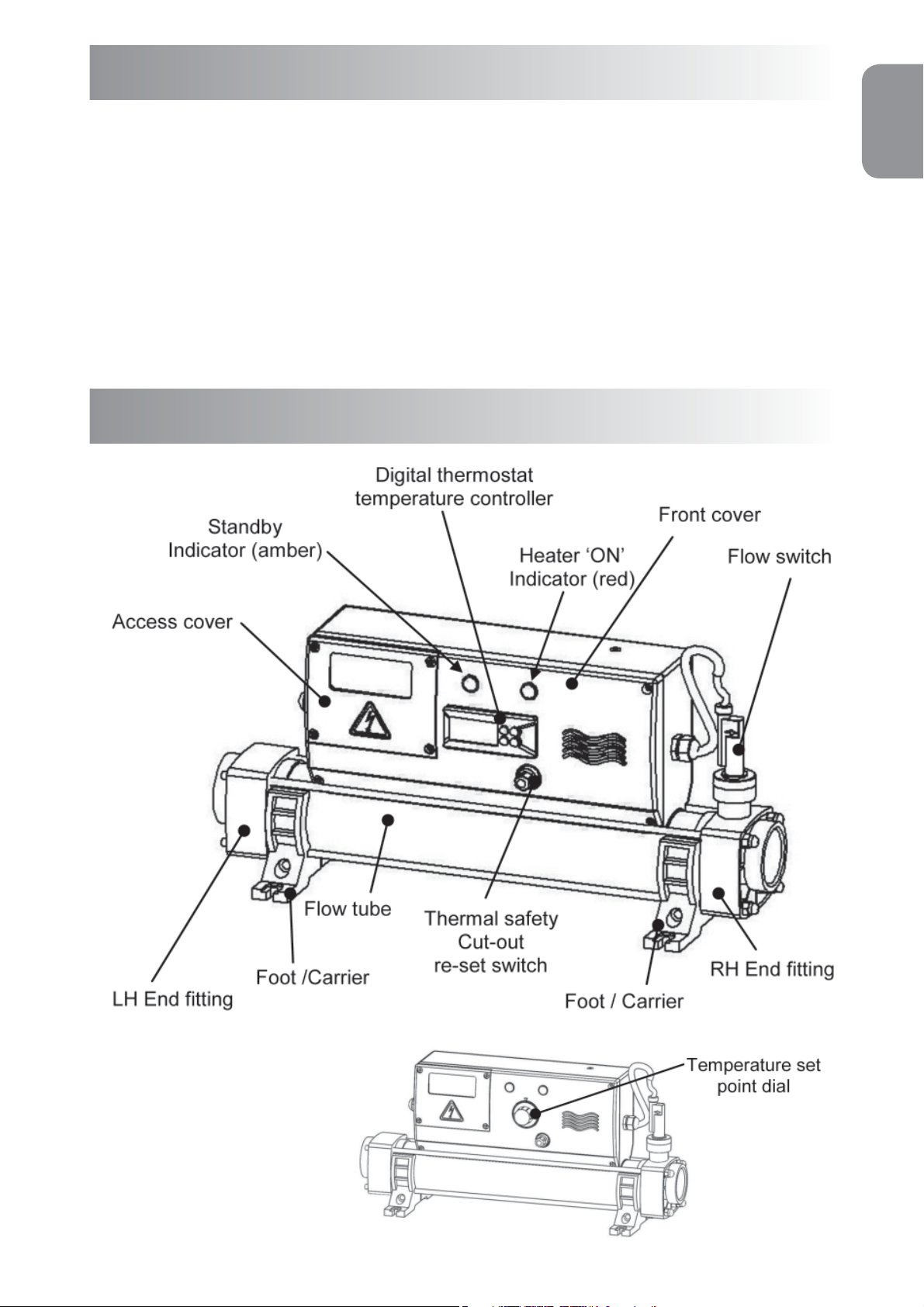
Product Overview
ENGLISH
DIGITAL
Version
ANALOGUE
Version
Fig 1.
1
ENGLISH
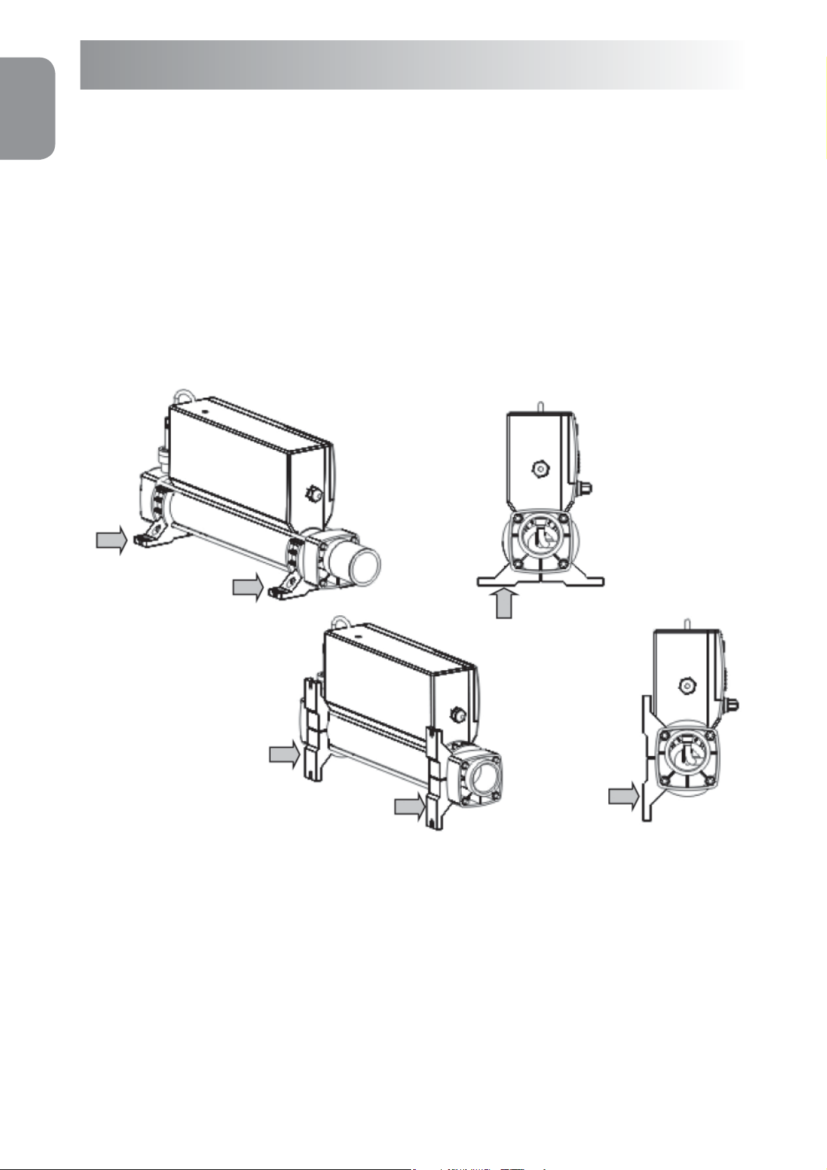
Positioning
Your heater must be horizontally or vertically sited allowing su cient
space for pipe connections and wiring, it should be screw xed securely to
a rm base or wall.
NOTE: See gure 2 for details of the foot arrangement when securing
to the wall or oor.
Floor mount ‘Foot position’
Fig 2.
Factory set oor
mount ‘Foot position’
To reset for wall
mount option,
undo the bolts and
re-assemble in the
vertical position as
shown.
Wall mount ‘Foot position’
The heater should be installed at a low point in the ltration system.
It should be positioned downstream (after) of the lter and upstream
(before) of any dosing or other water treatment plant. (see g.3)
NOTE : If the ow direction is reversed (explained later in this
booklet) the heater must remain sited after the lter.
2
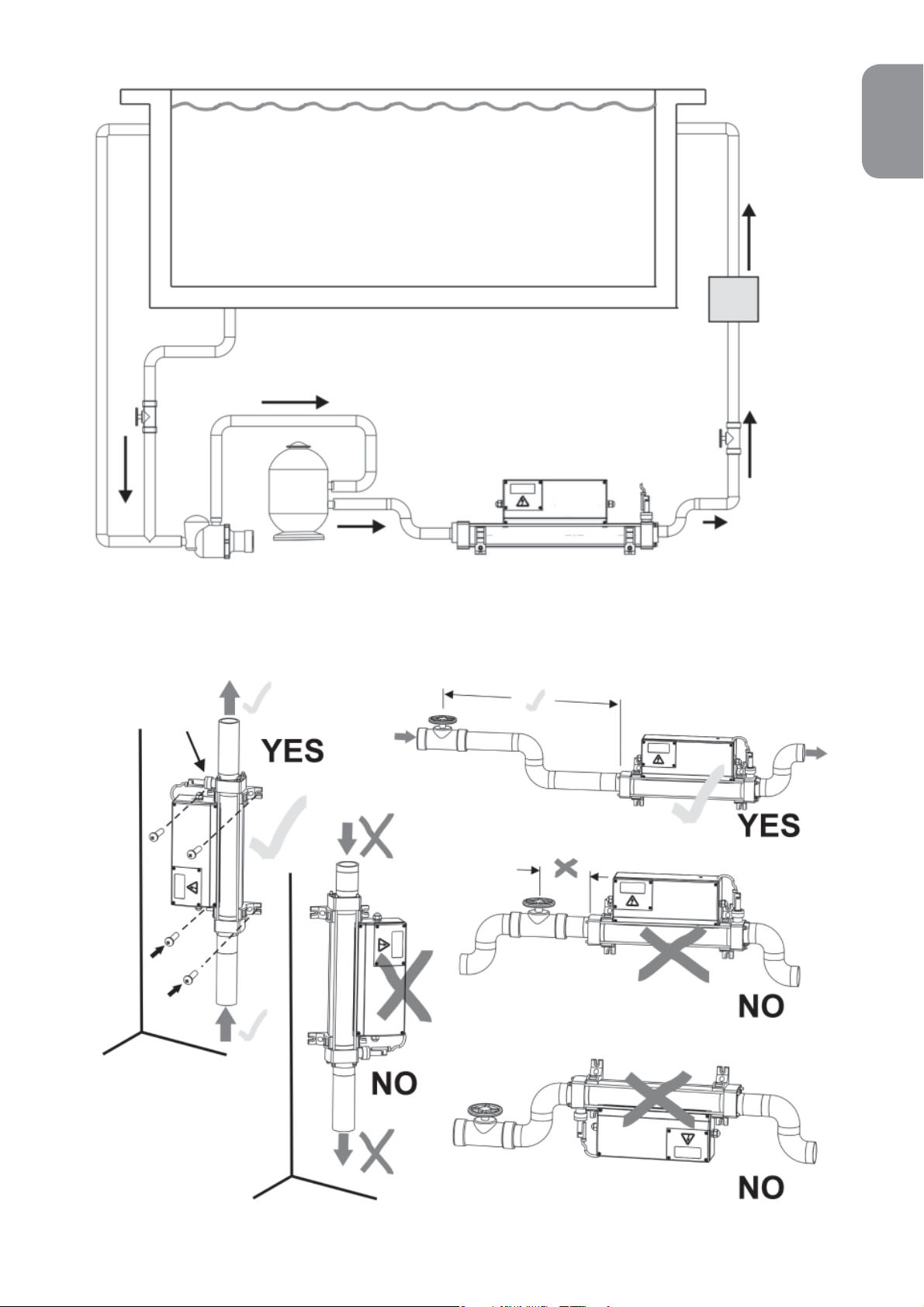
Fig 3.
PUMP
FILTER
POOL
ENGLISH
WATER
TREATMENT
VALVE
NON RETURN
VULCAN HEATER
Flow switch
at top
For vertical wall
mounting water
must always enter
at the bottom
Fig 4.
3

ENGLISH
Pipe Work
It is essential that the pipe work connecting to and from the heater
has a minimum bore (internal diameter) of 1¼” (32mm). To assist correct air
purging and to ensure the heater remains completely full of water during
operation, the return pipe which carries the water back to the pool must
incorporate a safety loop or ‘kick-up’ in the pipe as close as possible to the
heater (see g 4)
NOTE: When coupling to a exible pipe a safety loop can simply be
created by routing the pipe up and over an obstacle.
Remember to use pipe clips to securely fasten all hose connections.
Weather Protection
The heater must be installed within a dry weather proof enclosure.
Caution! If the heater is not used during winter months it must be drained to
prevent frost damage.
Electrical Connection
The heater must be installed in accordance with the country / regional
requirements & regulations. In any event the work must be carried out by
a quali ed electrician, who will provide a certi cate of conformity upon
completion of the work. The power supply must be tted with a RCD. If
required your electrician may replace the supplied cable entry gland with a
larger size to secure the cable powering the heater, this will not a ect your
warranty if carried out by a quali ed electrician.
Cable section: This should be calculated at 5-amp / mm for distances
up to 20 metres (these sections are indicative and should be checked and
adapted if necessary for cable lengths over 20 metres.
Remove Access Cover
to make the electrical
connections
(Quali ed electricians only)
Fig 5.
4
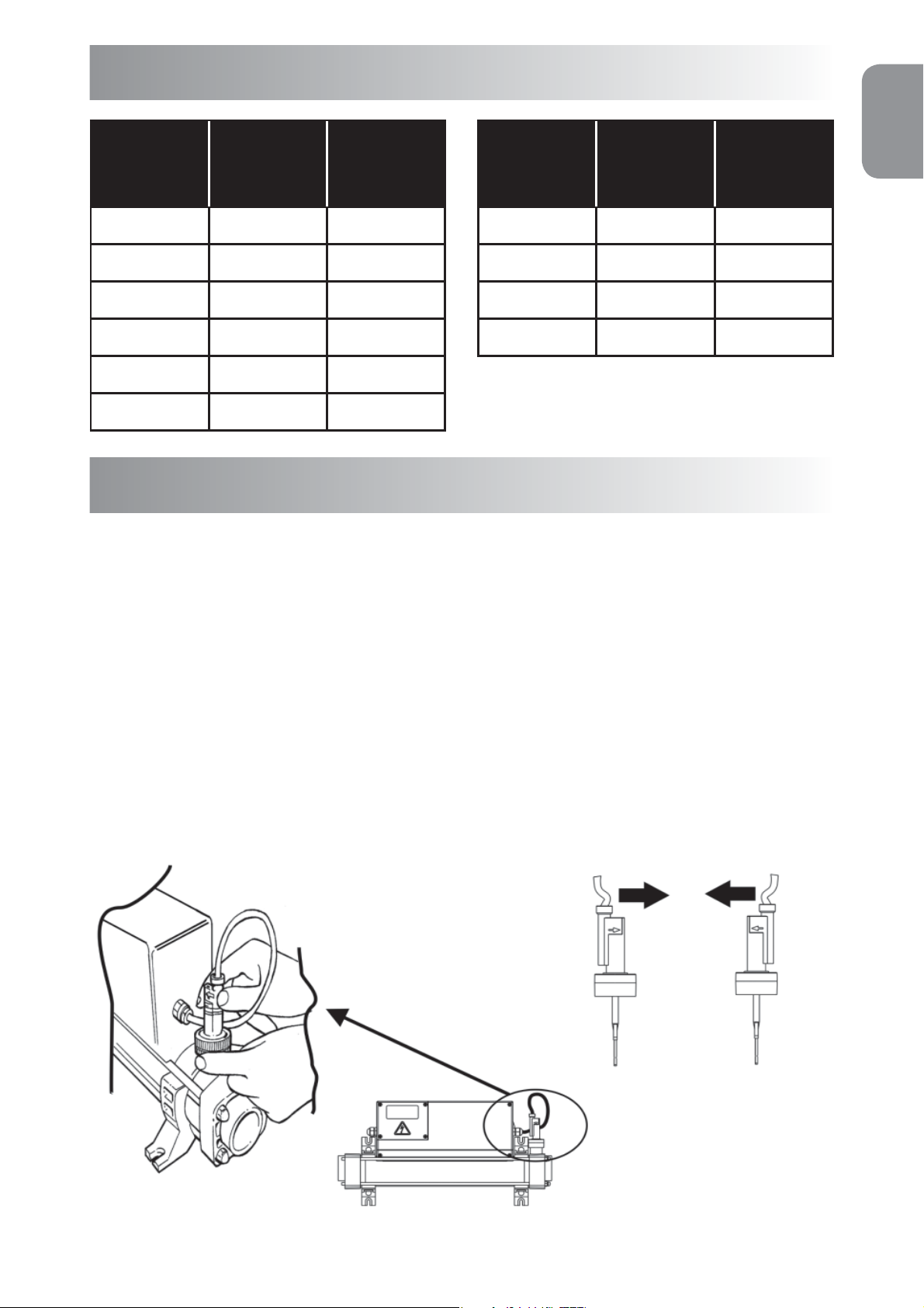
Power Requirements
Power
Output
3 - kW 230 13
4.5 - kW 230 20
6 - kW 230 27
9 - kW 230 40
12 - kW 230 53
15 - kW 230 66
Voltage
Amp
(V)
3 Phase
Power
Output
6 - kW 400 / 230V 9 / 15
9 - kW 400 / 230V 13 / 23
12 - kW 400 / 230V 18 / 31
15 - kW 400 / 230V 22 / 38
400 V Star /
230 V Delta
Amp
Flow Requirements
Your heater is factory set to accept input water ow entering on the left
and exiting on the right, this can be reversed by rotating the ow switch
ENGLISH
180 degrees (ie:½ turn, see g 6)
Warning! The ow switch paddle can be damaged when reversing the ow
direction if it is lifted by more than 5mm from its housing and turned with
force. If the ow switch has been rotated it is important to ensure that it is
nally locked in the correct orientation perpendicular (at right angles) to the
ow of water.
To reverse ow:
Loosen cap and rotate
Flow switch by 180 degrees
as shown. Always ensure
the arrow marked on the
plastic ow switch body is
in the same direction as the
water ow.
Factory set ow
Flow
Optional reverse
o w
Fig 6.
5
 Loading...