

Vulcan-Hart CEM10U ML-138077, CEM20U, CEM6U ML-138076, CEM6U, ML-138076 Installation & Operation Manual
...Page 1

ELECTRIC
COMBINATION OVEN
MODELS
CEM6U ML-138076
CEM10U ML-138077
INSTALLATION &
OPERATION MANUAL
CEM20U ML-138078
For additional information on Vulcan-Hart or to locate an authorized parts
and service provider in your area, visit our website at www.vulcanequipment.com
VULCAN-HART
DIVISION OF ITW FOOD EQUIPMENT GROUP, LLC
WWW.VULCANEQUIPMENT.COM
3600 NORTH POINT BLVD.
BALTIMORE, MD 21222
FORM 37466 (09-10)
Page 2

ELECTRIC COMBI OVEN
— 2 —
Page 3

ELECTRIC COMBI OVEN
TABLE OF CONTENTS
INSTALLATION, OPERATION AND CARE OF ELECTRIC COMBI OVEN ..................................5
GENERAL...................................................................................................................................5
UNPACKING ...............................................................................................................................5
INSTALLATION ...........................................................................................................................5
INSTALLATION CODES AND STANDARDS ...........................................................................5
COMBINATION OVEN STAND ASSEMBLY INSTRUCTIONS ................................................ 6
Unpacking ............................................................................................................................. 6
Assembly ..............................................................................................................................6
LOCATION ..................................................................................................................................7
LEVELING ................................................................................................................................... 7
ELECTRICAL SPECIFICATIONS ..............................................................................................7
Power Supply .......................................................................................................................8
Grounding .............................................................................................................................8
WATER REQUIREMENTS ........................................................................................................8
Water Treatment .................................................................................................................. 8
Water Supply Connection....................................................................................................9
Filter System ........................................................................................................................9
Drain Connection .............................................................................................................. 10
VENT HOOD ........................................................................................................................... 10
BEFORE FIRST USE ............................................................................................................. 10
OPERATION ................................................................................................................................. 11
OPERATING CONTROLS LOCATION.................................................................................. 11
Optional Internal Product Probe ....................................................................................... 11
Oven Vent Valve ................................................................................................................ 12
Oven Convection Fan ....................................................................................................... 12
Cooking Selector Knob ..................................................................................................... 12
Warming - Rethermalization Mode .................................................................................. 13
Combined Cooking............................................................................................................ 13
Convection Cooking .......................................................................................................... 13
Steam Cooking .................................................................................................................. 14
Thermostat Controlled Steam Cooking ........................................................................... 14
Oven Temperature Display .............................................................................................. 14
Oven Temperature Button ................................................................................................ 15
Oven Temperature Selector Knob ................................................................................... 15
Oven Timer Button............................................................................................................ 15
Oven Timer Knob .............................................................................................................. 15
Humidity Control ................................................................................................................ 16
Oven Light Button ............................................................................................................. 16
— 3 —
Page 4

ELECTRIC COMBI OVEN
TABLE OF CONTENTS (CONTINUED)
Fan Speed Selector .......................................................................................................... 16
Product Probe Temperature Selector Knob .................................................................... 17
Internal Product Temperature Probe Button ................................................................... 17
COOKING ................................................................................................................................18
Cooking with The Internal Product Probe ........................................................................ 18
Cook and Hold ................................................................................................................... 19
Displaying and Modifying Cooking Settings ..................................................................... 19
Cooking Settings ............................................................................................................... 19
CHANGE COOKING SETTINGS ............................................................................................ 20
Manually Lowering The Oven Temperature..................................................................... 20
Automatically Lowering Oven Temperature .................................................................. 20
DAILY SHUTDOWN ................................................................................................................ 20
EXTENDED SHUTDOWN ...................................................................................................... 20
CLEANING ..................................................................................................................................... 22
OVEN DRAINS ........................................................................................................................ 22
OVEN COMPARTMENT ......................................................................................................... 22
Daily ................................................................................................................................... 22
Weekly ............................................................................................................................... 22
DOOR GASKET ...................................................................................................................... 22
STAINLESS STEEL EQUIPMENT CARE AND CLEANING .................................................. 23
Recommended cleaners for specific situations ............................................................. 24
Review ............................................................................................................................... 24
MAINTENANCE ............................................................................................................................. 25
WATER TREATMENT SYSTEM ............................................................................................ 25
DOOR GASKET REPLACEMENT ......................................................................................... 25
OVEN LIGHT REPLACEMENT............................................................................................... 25
REMOVAL OF LIME SCALE DEPOSITS .............................................................................. 25
MESSAGES AND ALARMS .......................................................................................................... 26
MESSAGES ............................................................................................................................. 26
ALARMS................................................................................................................................... 26
TROUBLESHOOTING .................................................................................................................. 27
SERVICE AND PARTS INFORMATION ...................................................................................... 28
— 4 —
Page 5

ELECTRIC COMBI OVEN
INSTALLATION, OPERATION AND CARE OF
ELECTRIC COMBI OVEN
SAVE THESE INSTRUCTIONS FOR
FUTURE USE
GENERAL
Vulcan electric combination ovens are
produced with quality workmanship and
material. Proper installation, usage and
maintenance will result in many years of
satisfactory performance. It is suggested that
you thoroughly read this entire manual and
carefully follow all of the instructions provided.
It is a convection oven and a pressureless
steam oven combined into one. The steam is
generated inside the oven and circulated by a
fan. With the combined oven/steamer, three
cooking processes are available: Steam, hot
air, and combination. The combined oven
may be used to perform these types of cooking:
• Steam Cooking
• Baking
• Stewing
• Browning
INSTALLATION
Before installing, verify that the electrical supply
agrees with the specifications on the data
plate located on the lower front corner of the
right side panel. If the supply and equipment
requirements do not agree, do not proceed
with the installation. Contact your dealer or
Vulcan-Hart immediately.
This oven is shipped pre-wired with one of
the following voltages: 208/60/3, 240/60/3 or
480/60/3 VAC.
INSTALLATION CODES AND
STANDARDS
In the United States of America, the oven must
be installed in accordance with:
1. State and local codes.
2. National Electrical Code, ANSI/NFPA-70
(latest edition). Copies may be obtained
from The National Fire Protection
Association, Batterymarch Park, Quincy,
MA 02269.
• Grilling
• Braising
• Pre-Cooking
• Reheating
• Defrosting
Unpacking
Each oven is inspected before leaving the
factory. The transportation company assumes
full responsibility for safe delivery upon
acceptance of the shipment.
Immediately after delivery, unpack and check
for shipping damage. If the oven is damaged,
save the packing material and contact the
carrier immediately. There is a fifteen-day
limitation on filing freight damage claims with
the freight company. Freight damage is not
covered under warranty.
3. Vapor Removal from Cooking Equipment,
(NFPA-96, latest edition) available from NFPA.
In Canada, Vulcan-Hart ovens must be
installed in accordance with:
1. Local Codes
2. Canadian Electrical Code (CSA C22.2
No. 3, latest edition) available from the
Canadian Standards Association, 5060
Spectrum Way, Mississauga, Ontario,
Canada L4W 5N6
— 5 —
Page 6

ELECTRIC COMBI OVEN
COMBINATION OVEN STAND
ASSEMBLY INSTRUCTIONS
Unpacking
Each Combination Oven Stand is inspected
before leaving the factory. The transportation
company assumes full responsibility for safe
delivery upon acceptance of the shipment.
Immediately after delivery unpack and check
for shipping damage. If the stand is damaged,
save the packing material and contact the
carrier immediately. There is a fifteen-day
limitation on filing freight damage claims with
the freight company. Freight damage is not
covered under warranty.
Assembly
NOTE: Discard washers from kit.
Follow these procedures to properly assemble
the Adjustable Combination Oven Stand.
1. Remove the adjustable feet from the
bottom of the stand.
Allen Cap Screw
Figure 2: Allen Cap Screw Location
3. Push the leg onto the leg support and turn
the leg until the threaded holes are visible.
Insert the bolts and tighten them. Repeat
this step on each leg.
4. Once the legs are installed each leg must
be rotated so that the threaded holes, for
the tray support, face each other (front
and rear). These holes are used to mount
a tray support once the oven is installed on
the stand. The tray support will be installed
after the oven is installed on the stand. If
tray support is not used, insert the plastic
plugs into the four holes in the base.
Remove
adjustable
feet
Figure 1: Stand Foot Removal
2. Using the 10 mm Allen wrench, loosen but
do not remove the cap screw securing the
leg support to the stand base.
Align holes
Make sure
holes are
facing
each other
FRONT
Figure 3: Leg with Threaded Holes
in Proper Position
5. Tighten the Allen Cap screws in the base
of each leg.
6. Reattach the adjustable feet. The stand is
now ready for oven installation.
— 6 —
Page 7

ELECTRIC COMBI OVEN
7. Install tray support (if supplied) after oven
is installed onto stand. Use the four knurled
screws to secure the support to the legs.
FRONT
Figure 4: Assembled
Combination Oven Stand
LOCATION
Allow space for operating the oven. Do not
obstruct the ventilation port above the oven.
To provide ventilation access, allow 1" of
1
clearance on the left side of the oven and 2
/2"
clearance on the rear side of the oven. A
minimum of 18" must be provided on the right
side of the oven for operation, cleaning and
service. An optional heat shield assembly is
required if the clearance is less than 18" on
the right side of the oven.
LEVELING
Position the oven in its final installed location.
Place a level on the horizontal area of the
cabinet. Adjust the feet to level the oven in
both the left-to-right and front-to-rear
directions.
ELECTRICAL SPECIFICATIONS
The data plate is located on the front lower
right side of the oven.
Electrical Specifications Chart
Model Voltage Amperage Kilowatts Phase
CEM6U 208 26 9.4 3
CEM6U 240 25 10.3 3
CEM6U 480 11 9.4 3
CEM10U 208 43 15.5 3
CEM10U 240 40 16.8 3
CEM10U 480 19 15.5 3
CEM20U 208 54 19.5 3
CEM20U 240 48 24.0 3
CEM20U 480 27 22.1 3
— 7 —
Page 8

ELECTRIC COMBI OVEN
POWER SUPPLY
Connect the power supply as follows:
Electrical and grounding
connections must comply with applicable
portions of the National Electrical Code
and/or other local electrical codes.
Disconnect
the electrical power to the
machine and follow Lockout/
Tagout procedures.
1. Remove the right side panel from the oven.
The panel is held on by two screws on the
bottom and one screw on the top near the
back edge.
2. Wire to be sized per the National Electric
Code. Use copper wire rated for 125°C max.
3. Route the power supply cable through the
cable strain relief.
4. Connect the power supply cable to the
terminal block as shown on the label below
the terminal block.
5. Fasten the cable clamp firmly.
6. Reinstall the right side panel.
Plumbing connections must
comply with applicable sanitary, safety and
plumbing codes.
WATER REQUIREMENTS
Proper water quality can improve the taste of
the food prepared in the oven, reduce liming in
the oven cavity and extend equipment life.
Local water conditions vary from one location
to another. Ask your municipal water supplier
for details about your local water supply prior
to installation.
Presence of sediment, silica, excess chlorides or
other dissolved solids may lead to a
recommendation for alternate form(s) of water
treatment. Test the water with a TDS meter or the
test strip included with the oven. Other factors
affecting steam generation are iron content, amount
of chlorination and dissolved gasses.
Water Treatment
A local water treatment specialist should be
consulted before installing steam generating
equipment. It is recommended that you have
your water tested.
Supply Pressure 20-60 psig
L1 L2 L3
Power
Cord
L1 L2 L3
1234567
¥L1¥L2¥
PE
PE
89
L3
Terminal Block
10
Wiring Label
Figure 5: Power Supply Cable Connection
Grounding
The oven must be properly grounded.
Connect the ground conductor to the
terminal block in the position indicated on
the terminal block label.
Hardness* Less than 3 grains
Silica Less than 13 ppm
Total Chlorine/ 0 ppm
Chloramine**
Chlorides*** Less than 30 ppm
PH Range 7 – 8
Undissolved Solids Less than 5 microns
* 17.1 ppm = 1 grain of hardness
** Total Chlorine of 4.0 ppm is the max limit for the
building water supply. A carbon block filter must still be
used to remove all Chlorine and Chloramines from the
water. Failure to do so will result in corrosion and rust in
the cooking cavity which is not covered under warranty.
*** If the Chlorides exceed 30 ppm and the oven is
used more than 8 hours during the day in steam or
combination mode the cavity will require rinsing every
8 hours. Failure to do so will result in corrosion and
rusting of the oven cavity and interior parts. RO water
treatment system can be installed to eliminate
chlorides from the water and reduce the hardness.
— 8 —
Page 9
ELECTRIC COMBI OVEN
If the water supply fails to meet these
standards, it will be necessary to install a
water treatment system.
The use of strainers or filters will not remove
minerals from the water
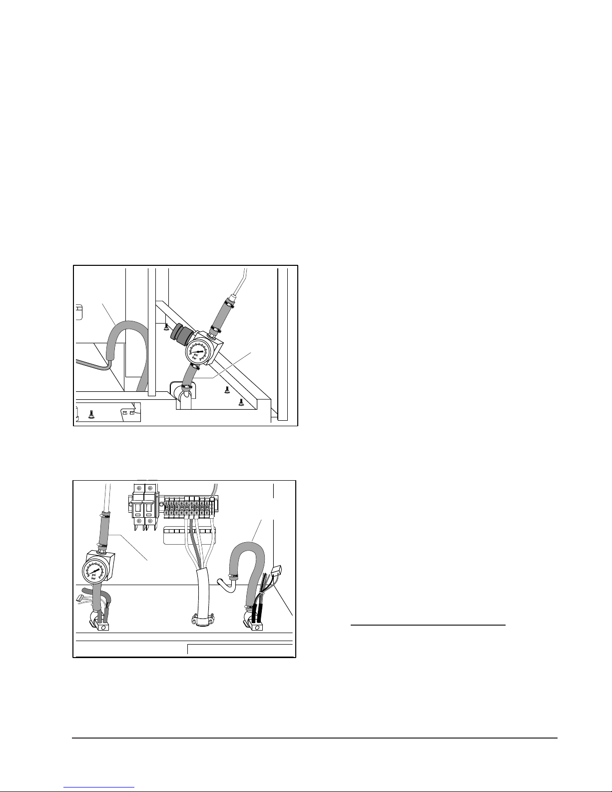
Water Supply Connection
Connect the treated cold water supply line,
3
min of
/8" ID, to the 3/4" garden hose inlet on
the underside of the Combi Oven. Connect
3
the untreated cold water supply line to the
/4"
garden hose, also on the underside of the
Combi Oven. Refer to Figures 6 and 7.
Unfiltered
water
supply
9
10
Filtered
water
supply
A water filter system is required for the water
supply line going to the treated water inlet of your
Combi Oven. Follow the recommendations for
use and installation instructions shipped with
the water filter. If a water filter is not installed, the
Combi Oven warranty is limited.
NOTE: Failure to properly connect the water
lines will result in equipment failure
that is not covered under warranty.
A manual shutoff valve must be provided in a
convenient location near the Combi Oven.
Filter System
• In addition to filtration for the control of
solids, you must have a carbon block filter
installed and maintained. Carbon block
filters remove the chlorine and chloramines
disinfectants from the water. Chlorine/
chloramines will erode the oven cavity,
rack guides, racks, and internal
components, which is not covered under
warranty. Check with your local water
treatment specialist for proper sizing and
replacment intervals for the carbon block
cartridge.
Figure 6: Water Supply Connection
for CEM6U and CEM10U
L1 L2 L3
PE
Unfiltered Water
Connection
PE
L1 L2 L3
1234567
Filtered Water
Connection
¥L1¥L2¥
89
10
L3
Figure 7: Water Supply Connections
for CEM20U
• Water feed lines to the oven must be flushed
before final connection. Particles in the water
could clog tubing and components that
supply water for steam production and drain
cooling. If the water supply is not free of
sediment or cloudy after several minutes of
flushing, a sediment filter must be installed
before use.
• If you have purchased a water filter
system from Vulcan-Hart, please follow
the instructions provided with the filter
system. At the time of installation you
must register your Combi Oven at
www.vulcanhart.com/filterreg or use the
reply card supplied with your unit. You will
need to register your Combi Oven at each
filter change to insure your standard and
extended warranty is maintained.
Filter purchase invoices and maintenance
records must be provided with warranty claims.
— 9 —
Page 10

ELECTRIC COMBI OVEN
DRAIN CONNECTION
In order to avoid any backpressure
in the oven, do not make a solid connection to
any drain. Failure to do so can damage the
oven and will void the warranty.
OR
12" (305 mm)
min.
Figure 8: Drain Connection
The 1¼" NPT threaded fitting on the drain
outlet must be extended a minimum of 12"
(305 mm) – maximum of 72" (1829 mm)
away from the Comb Oven base, to an open
air gap type drain. Do not reduce the 1¼"
NPT drain piping throughout its length.
Not supplied
VENT HOOD
Local codes may require the oven to be located
under an exhaust hood. Information on the
construction and installation of ventilating
hoods may be obtained from Vapor Removal
from Cooking Equipment, NFPA Standard No.
96 (latest edition).
BEFORE FIRST USE
Before using the oven for the first time, it must
be “burned in” to release any odors that might
result from heating the new surfaces in the
oven. Remove the racks and rack guides and
thoroughly clean in sink with soap and water.
Thoroughly clean with soap and water the
interior of the oven. Refer to cleaning
instructions in this manual. Operate the oven
at maximum thermostat setting for 45 minutes
in Convection Mode.
Make sure the hinged back of the oven cavity
is completely closed and the thumb screws
are secured properly.
Install the rack guides and racks.
Provide a suitable floor sink with a minimum
depth of 12" (305 mm). The floor sink is NOT
to be directly under the oven and should be at
a distance so that steam vapors will not enter
the Combi Oven from underneath. The drain
should slope down away from the oven ¼" for
every foot of drain pipe length. The drain pipe
should be either iron or copper. DO NOT use
PVC pipe; PVC pipe may lose its rigidity or
glue may fail.
In order to avoid any back pressure in the
oven, do not connect solidly to any drain
connection.
— 10 —
Page 11

6
7
8
9
12
15
17
18
21
2
3
4
5
10
11
13
14
19
20
1
16
OPERATION
The oven and its parts are
hot. Use care when operating, cleaning or
servicing the oven. The cooking
compartment contains live steam. Stay
clear while opening the door.
OPERATING CONTROLS LOCATION
The Control Panel consists of the following
controls, which are explained in the
OPERATING CONTROLS FUNCTION section
of this manual:
1. Oven Vent Valve
2. Oven Convection fan
3. Cooking Selector Knob
4. Warming - Rethermalization
5. Combination Cooking
6. Off
7. Convection Cooking
8. Steam Cooking
9. Thermostat Controlled Steam Cooking
10. Oven Temperature Display (LED)
11. Oven Temperature Adjustment Knob
12. Oven Temperature Button
13. Oven Time Display (LED)
14. Oven Time Adjustment Knob
15. Oven Timer Button
16. Humidity Control (Spritzer), (Humidity
Injector)
17. Oven Light Button
18. Fan Speed Selector Button (Full & Half
Speed)
ELECTRIC COMBI OVEN
Optional Internal Product Probe
19. Internal Product Probe Temperature
Display (LED)
20. Internal Product Probe Temperature
Adjustment Knob
21. Internal Product Probe Button Control
panel.
Figure 9: Operating Control Location
— 11 —
Page 12

ELECTRIC COMBI OVEN
Oven Vent Valve
The Oven Vent Valve opens or closes the Vent
to adjust the amount of steam venting from the
oven. Pull the Oven Vent Valve out to open it.
Push it in to close it.
Figure 10: Oven Vent Valve
Oven Convection Fan
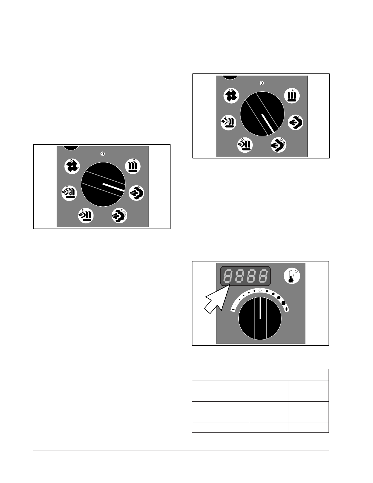
Cooking Selector Knob
The Cooking Selector Knob has seven
selectable positions corresponding to the
different cooking modes of the oven, or the off
position as shown. When a cooking mode is
selected, the respective LED light will flash
and after a few seconds, the control panel will
illuminate, indicating that the oven is prepared
for cooking.
NOTE: Select the desired cooking mode at
least ten minutes prior to cooking to
allow the oven to pre-heat and be
ready for cooking.
When the Oven Convection Fan is on, the LED
will be illuminated. The Oven Convection Fan
can be used to rapidly lower the oven
temperature. The Oven Timer Adjustment Knob
must be set to continuous, or a specific time
must be set, and the door must be closed in
order for the Oven Convection Fan to operate.
For quicker cool down, press the Humidity
Control button twice. This injects approximately
5 gal/h of water into the oven, cooling it faster.
Figure 12: Cooking Selector Knob
Figure 11: Oven Convection Fan
— 12 —
Page 13

ELECTRIC COMBI OVEN
Warming - Rethermalization Mode
Use the rethermalization mode to warm-up
(rethermalize) refrigerated foods. Warming is
accomplished in the combined mode at a
temperature range of 210°F (100°C) to 518°F
(270°C) on low speed.
Cold food shall not be added to the unit for
rethermalization while hot food is being held.
The Oven Timer Adjustment Knob must be
set to continuous, or a specific time must be
set, and the door must be closed in order for
the Oven Convection Fan to operate.
NOTE: It is recommended that the Vent Valve
remain open while warming food.
Foods cook quickly and brown evenly while
keeping the product moist and flavorful.
The Oven Timer Adjustment Knob must be
set to continuous, or a specific time must be
set, and the door must be closed in order for
the Oven Convection Fan to operate.
Figure 14: Combined Cooking
Convection Cooking
Figure 13: Warming - Rethermalization
Combined Cooking
The temperature range for combined cooking
is from 212°F (100°C) to 518°F (270°C). The
default value is 302°F (150°C). This cooking
method combines the benefits of steam and
convection. With combined cooking, cooking
time can be reduced from 5% to 50% even for
foods such as potatoes, carrots, etc. With
combined cooking it is possible to steam
foods and then glaze them to make them
crispy. Foods such as roasts, hams, etc.,
minimize their loss of weight and moisture.
For cooking temperatures ranging from 68°F
(20°C) to 518°F (270°C), hot air is evenly
distributed in the oven by a convection fan.
The default value is 302°F (150°C). This
method of cooking is ideal for baking, roasting,
toasting and grilling.
The Oven Timer Adjustment Knob must be
set to continuous, or a specific time must be
set, and the door must be closed in order for
the Oven Convection Fan to operate.
Figure 15: Convection Cooking
— 13 —
Page 14
ELECTRIC COMBI OVEN
Steam Cooking
The main advantage of steaming is the
nutritional values are maintained. It is the
most efficient means of cooking and the food
does not lose its moisture. Steaming is
conducted at 212°F (100°C). In the steam
mode the convection fan does not start until
the oven reaches 176°F (80°C).
The Oven Timer Adjustment Knob must be
set to continuous, or a specific time must be
set, and the door must be closed in order for
the Oven Convection Fan to operate.
Adjustment Knob must be set to continuous,
or a specific time must be set, and the door
must be closed in order for the Oven
Convection fan to operate.
Figure 17: Thermostat Controlled
Steam Cooking
Oven Temperature Display
Figure 16: Steam Cooking
Thermostat Controlled Steam Cooking
The temperature range for thermostatically
controlled steam cooking is from 68°F (20°C)
to 210°F (99°C). This method of cooking is
ideal for foods that have already been
processed, portioned and vacuum packaged.
The main advantages of this method of cooking
are the ability to cook in batches, food is
preserved longer, there is minimal weight
loss and the nutritional values are maintained.
After selecting the desired cooking method,
the Oven Temperature Display will display the
default temperature. The default temperature
is 302°F (150°C) During cooking, the display
will indicate the set temperature of the oven.
Figure 18: Oven Temperature Display
Temperature Ranges
Mode °F °C
Steam 212°F 100°C
Rethermalization 210–518°F 100–270°C
Combined 212–518°F 100–270°C
Convection 68–518°F 20–270°C
— 14 —
Page 15

ELECTRIC COMBI OVEN
Oven Temperature Button
During a cooking cycle, press the Oven
Temperature Button to display current oven
temperature.
Figure 19: Oven Temperature Button
Oven Temperature Selector Knob
The Oven Temperature Selector Knob is used
to change the desired oven cooking
temperature. Press the Oven Temperature
Button, then turn the Oven Temperature
Selector Knob clockwise to increase or counter
clockwise to decrease setting. The Oven
Temperature Button must be pressed to
change the temperature during operation.
Oven Timer Button
The Oven Timer button is used to change the
timer display and to silence the audible end of
the cook cycle alarm. During cooking, the
timer displays the remaining time. Pushing
the Oven Timer button toggles the display to
the oven set time.
Figure 21: Oven Timer Button
Oven Timer Adjustment Knob
The Oven Timer Adjustment Knob is used to
change the desired oven cooking time. To
adjust the time, turn the timer knob clockwise
to increase the time or counterclockwise to
decrease the time. The oven can also be
placed in continuous cooking mode by turning
the Oven Timer Adjustment Knob
counterclockwise until “Cont” displays.
Figure 20: Oven Temperature
Selector Knob
Figure 22: Oven Timer Adjustment Knob
— 15 —
Page 16

ELECTRIC COMBI OVEN
Humidity Control
The Humidity Control button controls the
level of moisture in the oven. This is essential
for cooking products with low moisture
content such as bread, biscuits, cakes and
soft items. The Humidity Control button is
also used to prevent roasts from burning or
losing their moisture. The Humidity Control
button has two positions. Pressing the
button once (the left LED will illuminate)
injects approximately 1 Gal/h (4 l/h) of water
into the oven while cooking. Pressing the
button again (the right LED will illuminate)
injects approximately 5 Gal/h (18 l/h) of
water into the oven while cooking. To turn
the Humidity Control off, press the button
again (both LED lights will extinguish).
NOTE: The humidity control button only works
in Convection Cooking and Oven
Convection Fan modes.
LED
Figure 23: Humidity Control
Oven Light Button
The Oven Light button turns the oven light on
or off when the oven is on.
LED
Figure 24: Oven Light
Fan Speed Selector
The Fan Speed Selector controls the speed of
the Oven Convection Fan. This makes it
possible to reduce the amount of air in the
oven for cooking delicate items that require
less airflow. The button has two positions;
Low speed and High speed. High is used for
fast cooking while Low is used for cooking
delicate items or for steaming. The LED lights
in the corner of the button correspond to the
fan speed selected. Pressing the button once
will select the Low Speed setting and the left
LED will be illuminated. Pressing the button
again will select the High Speed setting and
the right LED will be illuminated.
LED
Figure 25: Fan Speed Selector
— 16 —
Page 17

ELECTRIC COMBI OVEN
Internal Product Probe Temperature
Selector Knob
The optional Internal Product Probe that can
be attached to maintain specific internal
cooking temperatures. The temperature range
is from 68°F (20°C) to 210°F (99°C). For such
items as roast-beef, pâté, etc., the internal
cooking temperature is important to maintain.
By using the Internal Product Probe, the oven
will switch off when the desired internal cooking
temperature is reached. Setting the
temperature for the Internal Product Probe
disables the cook time timer. The Internal
Product Probe can be used with all the optional
cooking methods: steaming, convection
cooking, combined cooking. The internal
temperature guide for cooking with the Internal
Product Probe can be found on page 21.
The Internal Product Probe Temperature
Selector Knob controls the desired internal
cooking temperature sensed by the Internal
Product Probe. To adjust the desired internal
temperature, turn the selector knob clockwise
to increase the internal temperature or
counterclockwise to decrease the internal
temperature.
Internal Product Temperature
Probe Button
Press the Internal Product Temperature Probe
Button to display the current internal
temperature of the product being cooked.
Figure 27: Internal Product Temperature
Probe Button (if Installed)
Figure 26: Internal Product Probe
Temperature Selector Knob (if Installed)
— 17 —
Page 18

ELECTRIC COMBI OVEN
COOKING
Make sure the hinged back of the oven cavity
is completely closed and the thumb screws
are secured properly.
To start up oven:
1. Select the desired cooking mode.
2. Select the desired cooking time by turning
the selector knob clockwise to the desired
time. The Oven Timer Adjustment Knob
must be set to continuous, or a specific
time must be set, and the door must be
closed in order for the Oven Convection
Fan to operate.
Turning the timer knob counterclockwise until
“Cont” displays will place the oven in
continuous cooking mode.
When the desired time is reached the oven will
stop, an audible alarm will sound for one (1)
minute and the display will change to “End”.
2. Place the product with probe in place, in or
near the center of the oven.
3. Remove the protective cap and insert the
probe electrical connector into the probe
connection on the oven as shown below
(Figure 28).
Internal
Product
Temperature
Probe
Probe
Electrical
Connector
3. To cancel the audible alarm, press the
Timer Display button.
In order to set a new cooking time, the Timer
Display button must first be pressed.
4. To cancel continuous cooking, place the
Oven Timer Knob to zero or turn the
Cooking Selector Knob to 0.
In the 212°F (100°C) steam mode, the
convection fan will not come on until the oven
temperature reaches 176°F (80°C). This
allows the product to be cooked when the fan
is not on.
The oven is equipped with a cooling fan for the
internal components. It will start when the
oven is on and stop approximately ten (10)
minutes after the oven is turned off.
Cooking with the Internal Product
Temperature Probe
To cook using the Internal Product
Temperature Probe:
1. Insert the probe into the product to be
cooked. Place the tip of the probe in or
near the center of the product.
Figure 28: Cooking with the
Internal Product Temperature Probe
4. Close the oven door.
5. Select the desired cooking method.
6. Push the Internal Product Temperature
Probe LED button. The button LED will
illuminate. The display will show a pre-set
temperature and the minute counter
display will be deactivated.
7. Select the desired internal cooking
temperature. After a few seconds, the
oven will begin cooking and the product
internal temperature will be displayed.
8. During the cooking cycle, the minute
counter will display the amount of elapsed
time.
9. Cooking will stop when the product internal
temperature reaches the desired set
temperature.
If the probe exceeds 212°F (100°C) “Ovl”
(Overtemp) will show in the display.
The oven will automatically enter the Cook
and Hold Mode when the desired product
internal temperature is reached.
— 18 —
Page 19

ELECTRIC COMBI OVEN
If the Internal Product Temperature Probe is
hot at the start of the cooking cycle due to
oven pre-heating, the display will flash until
the actual temperature of the food is displayed
and then cooking will commence.
Cook and Hold
Cook and Hold is only available when using
the Internal Product Temperature Probe. At
the end of the cooking cycle, the product is
kept warm without its temperature falling below
158°F (70°C). The oven will maintain 158°F
(70°C) as long as the product is in the hold
mode. The display will flash “Hold” for ten (10)
minutes. If the oven is not switched off or the
product removed after ten (10) minutes, the
display will change to a steady “Hold”. The
Timer Display button can be pressed to see
how long the product has been in Hold mode.
To exit the Cook and Hold mode, turn the
Selector Knob to 0.
DISPLAYING AND MODIFYING
COOKING SETTINGS
NOTE: If probe is removed without changing
the cooking mode alarm PGno will
display. When changing from probe to
time cooking, you must switch the
mode to time or PGnu will display.
Figure 29: Cooking Settings
Cooking Settings
The setting can be changed at any time by
pressing one of the buttons displayed in Figure
29. When selected, the appropriate LED will
illuminate. The display will show either the
oven temperature, the set time or the Internal
Product Temperature Probe temperature.
After a few seconds, the LED will extinguish
and the display will change back to the
previous display.
— 19 —
Page 20

ELECTRIC COMBI OVEN
Change Cooking Settings
To change either the set temperature, timer or
internal temperature while cooking:
1. Press the relevant button and the LED will
illuminate.
2. Turn the knob.
After a few seconds, the new parameter will
be accepted and the LED will extinguish.
Manually Lowering The Oven Temperature
To manually lower the oven temperature:
1. Close the oven door.
2. Turn selector knob to Oven Convection
Fan position and open vent.
3. Select the desired temperature.
4. The oven temperature will lower to the
desired temperature set.
DAILY SHUTDOWN
1. Place the Selector Knob to 0 (OFF).
2. Clean the oven interior.
3. Leave door open.
EXTENDED SHUTDOWN
1. Perform DAILY SHUTDOWN procedure.
2. Turn off the circuit breakers.
3. Turn off the water supply.
4. Thoroughly clean the oven interior, door
seals, etc.
5. Leave door open.
Automatically Lowering Oven Temperature
If steaming or thermostatic steaming is
selected while the oven is still hot, water is
injected into the oven. This is so that the oven
temperature can be lowered quickly and
prevents food from being cooked at too high of
a temperature.
— 20 —
Page 21

ELECTRIC COMBI OVEN
Safe Cooking Temperatures
After desired cooking temperature is reached, remove meat from heat source and let stand 10 to 15 minutes before
carving. The amount of time required for resting varies with the size of the cut of your meat. During this resting time, the
meat continues to cook (meat temperature will rise 5 to 20 degrees after it is removed from the heat source) and the
juices redistribute.
NOTE: For additional information on safe cooking temperatures, refer to USDA Safe Food Handling.
Beef and Lamb
Roasts, Steaks & Chops
Rare 120 to 125°F (49 to 52°C) Center is bright red, pinkish toward the exterior portion.
Medium Rare 130 to 135°F (55 to 57°C) Center is very pink, slightly brown toward the exterior portion.
Medium 140 to 145°F (60 to 63°C) Center is light pink, outer portion is brown.
Medium Well 150 to 155°F (66 to 68°C) Not pink.
Well Done 160°F (71°C) and above Steak is uniformly brown throughout.
Ground Meat 160 to 165°F (71 to 74°C) No longer pink but uniformly brown throughout.
Beef Brisket 160°F (71°C) and above
Casseroles and Left overs 165°F (74°C)
Poultry
Poultry (Chicken & Duck) 165°F (74°C) Cook until juices run clear.
Turkey 165°F (74°C) Juices run clear – leg moves easily.
Stuffing (cooked alone or in turkey) 165°F (74°C)
Pork
Roasts, Steaks & Chops
Medium 140 to 145°F (60 to 63°C) Pale pink center.
Well Done 160°F (71°C) and above Steak is uniformly brown throughout.
Pork ribs, pork shoulders,
and pork loin 160°F (71°C) and above Medium to well done.
Sausage (raw) 160°F (71°C) No longer pink.
Ham
Raw 160°F (71°C)
Pre cooked 140°F (60°C)
Seafood
Fish (steaks, filleted or whole) 140°F (60°C) Flesh is opaque, flakes easily.
Tuna, Swordfish, & Marlin 125°F (52°C) Cook until medium rare.
Shrimp
Medium size, boiling 3 to 4 minutes Cook until medium rare.
Large size, boiling 5 to 7 minues Cook until medium rare.
Jumbo size, boiling 7 to 8 minutes Cook until medium rare.
Lobster
Boiled, whole 1 lb. 12 to 15 minutes Meat turns red and opaque in center when cut.
Broiled, whole 1 1/2 lbs. 3 to 4 minutes Meat turns red and opaque in center when cut.
Steamed, whole 1 1/2 lbs. 15 to 20 minutes Meat turns red and opaque in center when cut.
Baked, tails each 15 minutes Meat turns red and opaque in center when cut.
Broiled, tails each 9 to 10 minutes Meat turns red and opaque in center when cut.
Scallops
Bake 12 to 15 minutes Milky white or opaque, and firm.
Broil Milky white or opaque, and firm.
Clams, Mussels & Oysters Point at which their shells open – throw away any that do not open.
(Do not overcook or the meat will become dry and lose its flavor.)
(Do not overcook or the meat will become dry and lose its flavor.)
(Do not overcook or the meat will become dry and lose its flavor.)
(Do not overcook or the meat will become dry and lose its flavor.)
— 21 —
Page 22

ELECTRIC COMBI OVEN
CLEANING
NOTE: Do not use any cleaners (soaps,
detergents, disinfectants) that contain
chlorine or chlorides.
OVEN DRAINS
To keep the oven drain free of blockage:
1. Inspect the oven drain daily for any
blockage.
2. Remove any particles or debris from the
perforated strainer daily (more often if
needed).
After cooking greasy foods or seafood:
1. Make a solution of warm water and
detergent and pour ½ gallon (1.9 liters) of
it down into the compartment drain.
2. Rinse by pouring ½ gallon (1.9 liters) of hot
water down the drain.
Weekly
1. Thoroughly clean the exposed surfaces
(sides, front, door and top) with a damp
cloth.
2. Polish with a clean cloth.
3. To remove discolorations, use a
nonabrasive cleaner.
Door Gasket
1. Clean the gasket-sealing surface of the
oven doors to remove food acids for
maximum gasket life. Do not use any
solvents or sharp instruments.
2. Wash with a cloth moistened in a solution
of mild detergent and warm water.
3. Rinse with a fresh cloth moistened with
warm water to remove all traces of
detergent.
OVEN COMPARTMENT
Daily
1. Remove the oven racks and rack guides.
2. Wash the inside of the oven compartment
with a solution of warm water and detergent.
3. Rinse with warm water.
4. Remove the drain hole cover and wash
with a solution of warm water and nonchloride detergent.
5. Rinse with warm water.
4. Wipe dry with a clean cloth.
Never apply food oils or petroleum
lubricants directly to the door gasket.
Petroleum-based solvents and lubricants will
reduce the gasket life.
Leave Oven Door Open
Leave the oven door slightly open when the
oven is not in use. When the oven is idle, never
latch the door and apply pressure to the door
gasket. Leaving the gasket under pressure
can cause permanent deformation and reduce
the gasket life.
— 22 —
Page 23

ELECTRIC COMBI OVEN
STAINLESS STEEL EQUIPMENT
CARE AND CLEANING
Contrary to popular belief, stainless steels
ARE susceptible to rusting.
Corrosion on metals is everywhere. It is
recognized quickly on iron and steel as
unsightly yellow/orange rust. Such metals are
called “active” because they actively corrode
in a natural environment when their atoms
combine with oxygen to form rust.
Stainless steels are passive metals because
they contain other metals, like chromium,
nickel and manganese that stabilize the atoms.
400 series stainless steels are called ferritic,
contain chromium, and are magnetic; 300
series stainless steels are called austenitic,
contain chromium and nickel; and 200 series
stainless, also austenitic, contains
manganese, nitrogen and carbon. Austenitic
types of stainless are not magnetic, and
generally provide greater resistance to
corrosion than ferritic types.
With 12-30 percent chromium, an invisible
passive film covers the steel’s surface acting as
a shield against corrosion. As long as the film is
intact and not broken or contaminated, the metal
is passive and stainless. If the passive film of
stainless steel has been broken, equipment
starts to corrode. At its end, it rusts.
steel. Other deposits from food preparation and
service must be properly removed.
Chlorides are found nearly everywhere. They
are in water, food and table salt. One of the
worst chloride perpetrators can come from
household and industrial cleaners.
So what does all this mean?
Don’t Despair!
Here are a few steps that can help prevent
stainless steel rust.
1. Use the proper tools.
When cleaning stainless steel products,
use non-abrasive tools. Soft cloths and
plastic scouring pads will not harm steel’s
passive layer. Stainless steel pads also
can be used, but the scrubbing motion
must be in the direction of the
manufacturer’s polishing marks.
2. Clean with the polish lines
Some stainless steel comes with visible
polishing lines or “grain.” When visible
lines are present, always scrub in a motion
parallel to the lines. When the grain cannot
be seen, play it safe and use a soft cloth or
plastic scouring pad.
3. Use alkaline, alkaline chlorinated or
non-chloride-containing cleaners.
Enemies of Stainless Steel
There are three basic things which can break
down stainless steel’s passivity layer and
allow corrosion to occur.
1. Mechanical abrasion
2. Deposits and water
3. Chlorides
Mechanical abrasion means those things that
will scratch a steel surface. Steel pads, wire
brushes and scrapers are prime examples.
Water comes out of the faucet in varying degrees
of hardness. Depending on what part of the
country you live in, you may have hard or soft
water. Hard water may leave spots, and when
heated leave deposits behind that if left to sit, will
break down the passive layer and rust stainless
While many traditional cleaners are loaded
with chlorides, the industry is providing an
ever-increasing choice of non-chloride
cleaners. If you are not sure of chloride
content in the cleaner used, contact your
cleaner supplier. If your present cleaner
contains chlorides, ask your supplier if
they have an alternative. Avoid cleaners
containing quaternary salts; it also can
attack stainless steel and cause pitting
and rusting.
4. Treat your water.
Though this is not always practical,
softening hard water can do much to
reduce deposits. There are certain filters
that can be installed to remove distasteful
and corrosive elements. To insure proper
water treatment, call a treatment specialist.
— 23 —
Page 24

ELECTRIC COMBI OVEN
5. Keep your food equipment clean.
Use alkaline, alkaline chlorinated or nonchloride cleaners at recommended strength.
Clean frequently to avoid build-up of hard,
stubborn stains. If you boil water in stainless
steel equipment, remember the single most
likely cause of damage is chlorides in the
water. Heating cleaners that contain chlorides
has a similar effect.
6. Rinse, rinse, rinse.
immediately. The sooner you wipe off
standing water, especially when it contains
cleaning agents, the better. After wiping
equipment down, allow it to air dry; oxygen
helps maintain the stainless steel’s
passivity film.
7. Never use hydrochloric acid (muriatic
acid) on stainless steel.
8. Regularly restore/passivate stainless
steel.
If chlorinated cleaners are used, rinse and
wipe equipment and supplies, and dry
Recommended cleaners for specific situations
JOB CLEANING AGENT COMMENTS
Routine cleaning Soap, ammonia, Apply with cloth or sponge
detergent, Medallion
Fingerprints & smears Arcal 20, Lac-O-Nu Ecoshine Provides barrier film
Stubborn stains & Cameo, Talc, Zud, Rub in direction of polish lines
discoloration First Impression
Grease & fatty acids, Easy-off, De-Grease It Oven Aid Excellent removal on all
blood, burnt-on-foods finishes
Grease & oil Any good commercial detergent Apply with sponge or cloth
Restoration/Passivation Benefit, Super Sheen
Review
1. Stainless steels rust when passivity (filmshield) breaks down as a result of scrapes,
scratches, deposits and chlorides.
2 Stainless steel rust starts with pits and
cracks.
3. Use the proper tools. Do not use steel
pads, wire brushes or scrapers to clean
stainless steel.
5. Soften your water. Use filters and softeners
whenever possible.
6. Wipe off cleaning agent(s) and standing
water as soon as possible. Prolonged
contact causes eventual problems.
To learn more about chloride-stress corrosion
and how to prevent it, contact the equipment
manufacturer or cleaning materials supplier.
4. Use non-chlorinated cleaners at
recommended concentrations. Use only
chloride- free cleaners.
Developed by Packer Engineering, Naperville, Ill., an
independent testing laboratory.
Provided courtesy of NAFEM.
— 24 —
Page 25

MAINTENANCE
Light Lens
Lens Gasket
Light Bulb
ELECTRIC COMBI OVEN
The oven and its parts are
hot. Use care when operating, cleaning or
servicing the oven. The cooking
compartment contains live steam. Stay
clear while opening the door.
Water Treatment System
A water treatment system is recommended
for the combination oven. Refer to the
supplier’s manual for normal maintenance
procedures for proper scale-free operation.
Removal of Lime Scale Deposits
The oven cavity should be delimed when symptoms
occur (see Troubleshooting Chart). This is in
accordance with the minimum preventive
maintenance schedule required by warranty.
Items required (not provided):
• Deliming material (Recommended product
Scale Release™)
Door Gasket Replacement
Call your local service agent to replace the
gasket.
Oven Light Replacement
Do not touch new bulb glass with
bare hand.
1. Remove the oven rack and rack guides to
gain access to the light/s.
2. Remove the screws securing the light
lens to the cabinet.
3. Carefully remove the lens avoid damaging
the lens gasket.
4. Remove and replace the defective light bulb.
5. If the gasket has come loose, secure it.
6. Reinstall the lens cover making sure the
gasket is properly seated.
• Plastic or rubber gloves
• Safety goggles or face shield
• Measuring cup
• 1-gallon container for mixing the deliming
solution
Deliming solution may cause the surface
of aluminum measuring tools to tarnish or etch.
Figure 30: Oven Light
— 25 —
Page 26

ELECTRIC COMBI OVEN
MESSAGES AND ALARMS
Messages
When applicable, the Oven Timer LED will display the following messages:
LCD DISPLAY MESSAGE DESCRIPTION
door The oven door is open, or the door drip tray is not in place or is missing.
Cont The Selector Knob has been rotated counterclockwise and
the oven has been placed in continuous operation mode.
HoLd (Flashing) Cook cycle is complete and oven is entering the Cook and
Hold mode.
HoLd (Steady) The oven is in Cook and Hold mode.
End Cooking has ended.
Alarms
When applicable, the Control Panel LED will display the following alarms:
LCD ALARM DISPLAY DESCRIPTION
P1NO Oven temperature sensor broken or disconnected.
P6NO Internal Product Probe is broken and/or disconnected (it is still
possible to operate the oven without the Internal Product Probe).
P7NO Oven internal electrical compartment temperature has
exceeded 158°F (70°C).
NOT Convection Fan Motor failure
*OUL Internal Product Probe temperature has exceeded 210°F (99°C).
*VOLT The power supplied to the oven is either too high or too low
for proper operation.
*EEP Invalid parameter entry.
OVF The internal product probe temperature has exceeded
212°F (use symbol)/ 100°C.
* IMPORTANT: If any of the last three alarms are displayed, it is recommended that an Authorized
Vulcan-Hart service provider be called to examine and/or repair the oven.
— 26 —
Page 27

ELECTRIC COMBI OVEN
TROUBLESHOOTING
Problem Possible Cause / Suggested Corrective Action
Oven not heating/steaming No main power source / Check power source or circuit breaker.
Cooking Selector Knob in 0 position / Turn Selector Knob to
the desired cooking operation.
Door is open / Close the door.
Oven door leaks Damaged door gasket / Check door gasket for damage. If
adjustment or replacement is needed, contact your Authorized
Vulcan-Hart service provider.
Damage to gasket sealing surface / Contact your Authorized
Vulcan-Hart service provider.
Oven does not cook evenly Products may be too close together / Check to make sure
there is good air circulation between the products.
Product is dry Product humidity too high / Set Humidity Control to proper
setting.
Oven temperature too high / Set oven to correct temperature to
product being cooked.
Water accumulates in the oven Plugged drain or screen / Remove the cover from the oven drain
compartment and check for any obstructions.
Oven not leveled properly / See leveling instructions in the
INSTALLATION section of this manual.
Water not being supplied to the oven Water Manual Shutoff Valve is off / Turn the Manual Shutoff
Valve on.
Water pressure too low / Check water supply pressure.
Water filter is plugged / Refer to water filter manual. If symptom
persists, contact your Authorized Vulcan-Hart service provider.
Valve inlet screen is clogged / Contact your Authorized
Vulcan-Hart service provider.
Unit shuts down while operating Hi Limit trip / Contact your Authorized Vulcan-Hart service
provider.
— 27 —
Page 28

ELECTRIC COMBI OVEN
SERVICE AND PARTS INFORMATION
To obtain service and parts information, contact the Vulcan-Hart Service Agency
in your area or refer to our website www.vulcanequipment.com for a complete listing of authorized
service and parts providers.
When calling for service the following information must be available:
• Model Number
• Serial Number
• Manufacture Date (MD)
• Voltage
(09-10)
— 28 —
PRINTED IN U.S.A.
 Loading...