

Page 1
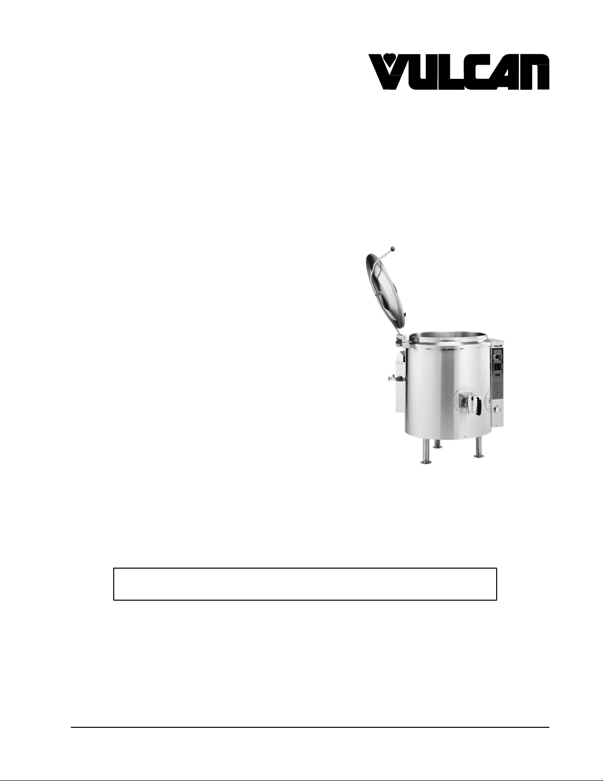
GAS 2/3 JACKETED
INSTALLATION &
OPERATION MANUAL
STATIONARY
AND
TILTING KETTLES
MODELS
K20GL ML-136090
K40GL ML-136091
K60GL ML-136092
K20GLT ML-136094
K40GLT ML-136095
K60GLT ML-136096
For additional information on Vulcan-Hart or to locate an authorized parts
and service provider in your area, visit our website at www.vulcanequipment.com
VULCAN-HART
DIVISION OF ITW FOOD EQUIPMENT GROUP, LLC
WWW.VULCANEQUIPMENT.COM
K40GL
3600 NORTH POINT BLVD.
BALTIMORE, MD 21222
FORM 35461 (June 2012)
Page 2
GAS KETTLES
IMPORTANT FOR YOUR
SAFETY
THIS MANUAL HAS BEEN PREPARED FOR PERSONNEL QUALIFIED TO INSTALL
GAS EQUIPMENT, WHO SHOULD PERFORM THE INITIAL FIELD START-UP AND
ADJUSTMENTS OF THE EQUIPMENT COVERED BY THIS MANUAL.
POST IN A PROMINENT LOCATION THE INSTRUCTIONS TO BE FOLLOWED IN THE
EVENT THE SMELL OF GAS IS DETECTED. THIS INFORMATION CAN BE OBTAINED
FROM THE LOCAL GAS SUPPLIER.
IMPORT
ANT
IN THE EVENT A GAS ODOR IS DETECTED, SHUT DOWN
UNITS AT MAIN
GAS COMPANY OR GAS SUPPLIER FOR SERVICE.
SHUTOFF VALVE
AND CONTACT THE LOCAL
FOR YOUR
SAFETY
DO
NOT STORE
VAPORS OR LIQUIDS IN THE VICINITY OF THIS OR ANY
OTHER APPLIANCE.
ALTERATION, SERVICE OR MAINTENANCE CAN CAUSE
PROPERTY DAMAGE, INJURY OR DEATH. READ
THE INSTALLATION, OPERATING AND MAINTENANCE
INSTRUCTIONS THOROUGHLY BEFORE INSTALLING OR
SERVICING THIS EQUIPMENT.
OR USE
IMPROPER INSTALLATION, ADJUSTMENT,
GASOLINE
OR OTHER FLAMMABLE
IN THE EVENT OF A POWER FAILURE, DO
OPERATE THIS DEVICE.
RETAIN THIS INSTRUCTION MANUAL FOR FUTURE
REFERENCE
NOT
ATTEMPT TO
— 2 —
Page 3

GAS KETTLES
— 3 —
CONTENTS
GENERAL
INSTALLATION
Unpacking......................................................................................................................................5
Installation Codes and Standards..................................................................................................5
Draw-Off Valves.............................................................................................................................5
Gas Connections ...........................................................................................................................6
Gas Connection Data ....................................................................................................................7
Testing the Gas Supply System.....................................................................................................7
Gas and Altitude Conversion .........................................................................................................8
Flue................................................................................................................................................9
Faucet Bracket ..............................................................................................................................9
Electrical Connection .....................................................................................................................9
Location .......................................................................................................................................10
Leveling
Before First Use
OPERATION......................................................................................................................................
Controls and Indicators................................................................................................................12
Before Operation .........................................................................................................................13
Operation .....................................................................................................................................13
Daily Shut Down ..........................................................................................................................13
Extended Shut Down ...................................................................................................................13
Venting.........................................................................................................................................14
Reservoir Jacket Water Level Check...........................................................................................14
Tilting Kettles ...............................................................................................................................14
Operating Data ............................................................................................................................14
STAINLESS STEEL EQUIPMENT CARE AND CLEANING
CLEANING
Compression Draw-Off Valve Cleaning Instructions....................................................................17
Plug Valve Cleaning Instructions .................................................................................................18
MAINTENANCE
Venting.........................................................................................................................................19
Filling The Reservoir Jacket ........................................................................................................19
Shutdown.....................................................................................................................................19
Service.........................................................................................................................................19
TROUBLESHOOTING ......................................................................................................................
...........................................................................................................................................
...................................................................................................................................
.......................................................................................................................................
...........................................................................................................................
..............................................................
........................................................................................................................................
................................................................................................................................
4
5
11
11
12
15
17
19
20
Page 4
GAS KETTLES
INSTALLATION, OPERATION AND
MAINTENANCE O F KGL AND KGLT
GAS
KETTLES
SERIES
SAVE THESE INSTRUCTIONS FOR FUTURE USE
GENERAL
V
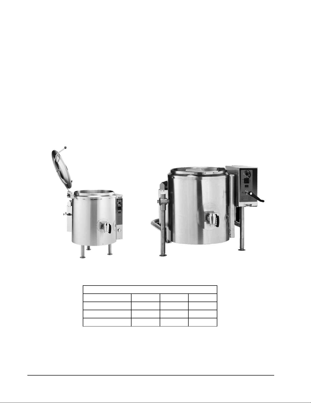
ulcan gas 2/3 jacketed kettles are produced with quality workmanship and material. Proper installation,
usage and maintenance will result in many years of satisfactory performance. It is suggested that you
thoroughly read this entire manual and carefully follow all of the instructions provided.
Model K40GL Model K40GLT
MODEL CHART
Model Gallons Quarts Liters
K20GL & K20GLT 20 80 76
K40GL & K40GLT 40 160 152
K60GL & K60GLT 60 240 228
— 4 —
Page 5
GAS KETTLES
— 5 —
INSTALLATION
UNPACKING
This kettle was inspected before leaving the factory. The transportation company assumes full
responsibility for safe delivery upon acceptance of the shipment.
Immediately after unpacking, check for possible shipping damage. If kettle damage is found, save the
packaging material and contact the carrier within 15 days of delivery. Freight damage is not covered
under Vulcan Warranty.
INSTALLATION CODES AND STANDARDS
In the United States, Vulcan kettles must be installed in accordance with:
1. State and local codes.
2. National Fuel
Gas
Code, ANSI-Z223.1 (latest edition). Copies may be obtained from the American
Gas Association, Inc.; 1515 Wilson Blvd.; Arlington, VA 22209.
3. National Electrical Code, ANSI/NFPA-70 (latest edition).
4. NFPA Standard NFPA-96, Vapor Removal from Cooking Equipment, latest edition, available
from the National Fire Protection Association, Batterymarch Park, Quincy, MA 02269.
In Canada, Vulcan ket tles must be installed in accordance with:
1. Local codes.
2. CAN/CGA-B149.1 National Fuel Gas Code (latest edition), available from the Canadian Gas
Association; 178 Rexdale Blvd.; Etobicoke, Ontario; Canada M9W 1R3.
3. CSA C22.2 No. 3 Canadian Electrical Code (latest edition), available from the Canadian Standards
Association, 178 Rexdale Boulevard, Etobicoke, Ontario, Canada M9W1R3
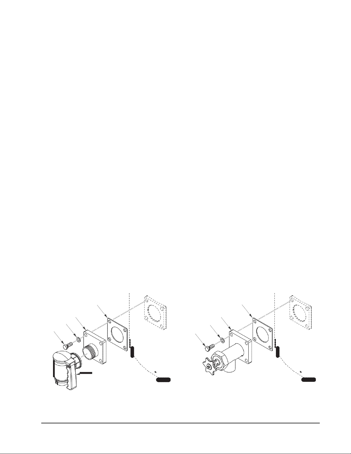
DRAW-OFF VALVES
Install the draw-off valve, if equipped. Install items 1 thru 5 for the plug style valve or items 1 thru 3
and item 6 for the compression style valve.
3
3
4 6
2
1
1
2
5
PLUG
DRAW-OFF VALVE
COMPRESSION
DRAW-OFF VALVE
Page 6

GAS KETTLES
GAS CONNECTIONS
Gas supply connections and any pipe joint compound must be resistant to the action of
propane gases.
Codes require that a gas shutoff valve be installed in the gas line ahead of the kettle.
Connect the gas supply line to the gas valve on the kettle. Make sure the pipes are clean and free of
obstructions, dirt and piping compound.
The gas line must be capable of delivering gas to the kettle without excessive pressure drop at the rate
specified on the nameplate. Suggested gas supply line pressure is 7" Water Column (1.75 kPa) for
natural gas and 11" Water Column (2.75 kPa) f or propane. Burner manifold pressure is (-)1.4" Water
Column (0.350kPa) for natural gas and (-)1.4" Water Column (0.350 kPa) for propane.
The proper sizing and installation of the gas connection is important for the machine to operate within
its design specifications. In some installations, the gas supply may not be sufficient enough to allow
all the gas equipment to operate properly at peak loads; or when other equipment with a high BTU/
hr. input requirement is operating. The connection to the machine becomes even more important in
this type of location. Flexible gas connectors with quick disconnect or swivel fittings (when used) and
gas connectors beyond the length necessary will reduce the BTU/hr. flow capacity to the machine.
NOTE: Do not use corrugated stainless steel tubing
for
commercial gas equipment supply connections.
NOTE: A straight gas connection is the ideal condition for the rated BTU/hr. flow capacity of the
connector. If a straight connection is not possible and a flexible gas connector is used, do not twist,
kink or excessively flex the connector beyond a U shape. Flexing the gas connector as described will
restrict gas flow or may damage the connector.
Changing a flexible gas connector may raise the BTU/hr. flow capacity enough to allow the machine
to
operate within its design specifications.
(i.e.
Removing the quick disconnect
fitting, installing a
shorter
gas connector or installing a larger diameter gas connector.) An alternative may be to move the
equipment to a different gas supply location in the kitchen. (i.e. Clos er to the main supply into the
kitchen or away from other equipment with high BTU/hr. input requirements.)
KETTLE WALL KETTLE WALL
INCORRECT INSTALLATION CORRECT INSTALLATION
Prior to lighting, check all joints in the gas supply line for leaks. Use soap and
water
solution.
After piping has been checked for leaks, all piping receiving gas should be fully purged to remove air.
Do not use an open flame.
— 6 —
Page 7

GAS KETTLES
— 7 —
are
will
used,
registered
Gas Connection Data
FLEXIBLE GAS CONNECTORS BTU/hr. FLOW CAPACITY
LENGTH
3
LENGTH
End Fittings - (1) Quick Disconnect
& (1)
Threaded
End Fittings - Both Threaded
1, 2
3
ID 36" 48" 60" 72" 36" 48" 60" 72"
1
/2"
3
/4"
1"
11/4"
77,000 68,000 60,000 55,000 120,000 106,000 93,000 86,000
218,000 180,000 158,000 139,000 256,000 225,000 198,000 175,000
379,000 334,000 294,000 279,000 512,000 451,000 397,000 350,000
615,000 541,000 476,000 419,000 946,000 833,000 733,000 645,000
1. Flow rating BTU/hr. 0.64 SP. GR @ 0.5 inch W.C. pressure drop.
2. BTU/hr. flow capacities are based on Dormont Mfg. Co. Supr-Safe gas line connectors and
provided
for
reference. Additional quick disconnect fi
ttings,
swivels, or manual shut
off
reduce the BTU/hr. flow capacities listed in this table. If other flexible gas connectors are
check the manufacturer’s specifications for BTU/hr. flow capacities. Supr-Safe is a
trademark of the Dormont Manufacturing Company.
3. The maximum length for a flexible gas connector is 72" per National Fuel Code standards.
BLACK IRON PIPE BTU/hr. FLOW CAPACITY
1, 2, 3
Natural Gas Nominal Inside Diameter of Pipe
Pipe Length
15'
30'
45'
60'
75'
90'
1
/
2"
76,000 172,000 345,000 750,000 1,220,000 2,480,000
52,000 120,000 241,000 535,000 850,000 1,780,000
43,000 99,000 199,000 435,000 700,000 1,475,000
38,000 86,000 173,000 380,000 610,000 1,290,000
3
/
4" 1" 1
1
/
4" 1
1
/
2" 2"
77,000 155,000 345,000 545,000 1,120,000
70,000 141,000 310,000 490,000 1,000,000
1. Flow rating BTU/hr. 0.64 SP. GR @ 0.3 inch W.C. pressure drop.
2.
BTU/hr.
flow capacities are based on Schedule 40 pipe, include a tolerance for pressure losses
in gas piping systems are provided for reference.
3. Count each 90° elbow as 3' of gas pipe for the purpose of calculating total pipe length.
valves
TESTING THE G AS SUPPLY SYSTEM
When gas supply pressure exceeds 1/2 psig (3.45 kPa), the kettle and its individual shutoff valve must
be disconnected from the gas supply piping system.
When gas supply pressure is 1/2 psig (3.45 kPa) or less, the kettle should be isolated from the gas
supply system by closing its individual manual shutoff valve.
Page 8

GAS KETTLES
GAS AND ALTITUDE CONVERSION
The kettle can be field converted to propane
gas or for operation at altitudes above 2000ft
elevation.
manometer
that
reads in 1/100" WC
A
and portable combustion analyzer are required.
Natural gas to Propane gas conversion:
1. Remove the right side controls
compartment side panel.
2. Locate the gas combination valve located
of
in the bottom
the controls compartment.
3. Turn S1 screw located right of manifold
pressure port (Fig. 1) clockwise to
completely close position. Then turn
counter clockwise 10 turns.
4. Pressure at inlet port should be between
11" and 13" WC.
5. Turn the unit on.
6. Fill the unit half way with cold water.
7. Run the unit for ½ hour to burn off any
residue in combustion chamber.
8. Using the combustion analyzer check
the flue gases. If the analyzer reads Co
Free Air the combustion gases should
not exceed 0.04 % or 400 PPM. If the
Fig. 1
analyzer does not read Co Free verify the
Co reading is below 100 PPM. If the reading is above, verify your settings and retest. If readings
are still high, call tech support at the number located on the front of this manual.
9. Attach the conversion data plate located in the bottom of the controls compartment with rivets
provided. The plate is to be mounted next to the kettle’s factory data plate.
10. Replace the controls compartment panel.
Propane gas to Natural gas
conversion:
1. Remove the right side controls compartment side panel.
2. Locat e the gas combination valve located in the bottom of the controls compartment.
3. Turn S1 screw located right of manifold pressure port (Fig. 1) clockwise to completely close
position. Then turn counter clockwise 16 turns.
4. Pressure at inlet port should be between 5" and 10.5" WC.
5. Turn the unit on.
6. Fill the unit half way with cold water.
7. Run the unit for ½ hour to burn off any residue in combustion chamber.
8. Using the combustion analyzer check the flue gases. If the analyzer reads Co Free Air the
combustion gases should not exceed 0.04 % or 400 PPM. If the analyzer does not read Co Free
verify the Co reading is below 100 PPM. If the reading is above verify your settings and retest.
If readings are still high call tech support at the number located on the front of this manual.
9. Attach the conversion data plate located in the bottom of the controls compartment with rivets
provided. The plate is to be mounted next to the kettle’s factory data plate.
10. Replace the controls compartment panel.
— 8 —
Page 9

— 9 —
GAS KETTLES
Altitude:
1. Remove the right side controls compartment side panel.
2. Locat e the gas combination valve located in the bottom of the controls compartment.
3. Turn S2 screw (Fig. 1) (using 5/64” Allen wrench), ½ turn clock wise
4. Turn the unit on.
5. Try five (5) times igniting the burner, if burner fails to ignite repeat step 3.
6. I nlet pressure setting:
a. Natural Gas: 5-7” WC
b. Propane: 11-13” WC
7. Fill the unit half way with cold water.
8. Run the unit for ½ hour to burn off any residue in combustion chamber.
9. Using the combustion analyzer check the flue gases. If the analyzer reads Co Free Air the
combustion gases should not exceed 0.04 % or 400 PPM. If the analyzer does not read Co Free
verify the Co reading is below 100 PPM. If the reading is above verify your settings and retest.
If reading is still high call tech support at the number located on the front of this manual.
10. Replace the controls compartment panel.
FLUE
DO NOT obstruct the flow of flue gases from the flue located on the rear of the kettle. It is required
that the flue gases be ventilated to the outside of the building through a ventilation system installed by
qualified personnel. The flue on the kettle should not be directly connected to any ventilation system.
From the termination of the flue to the filters of the hood venting system, a minimum clearance of 18"
(116 cm) must be maintained.
Information on the construction and installation of ventilating hoods may be obtained from Vapor
Removal from Cooking Equipment, NFPA-96 (latest edition), available from the National Fire Protection
Association, Batterymarch Park, Quincy, MA 02269.
FAUCET BRACKET
A bracket is provided for mounting a faucet on the kettle; this would allow the addition of water to the
kettle for the convenience of the food preparer. A faucet is available as an accessory.
NOTE: Do not use tap water from faucet to fill kettle jacket. Refer to Jacket Water & Jacket Water
Treatment.
ELECTRICAL CONNECTION
Electrical and
grounding connections
must comply with the
applicable
portions
of the national electrical code and/or other local electrical codes.
Electrical Grounding Instruction
This appliance is equipped with a three-prong (grounding) plug
for
your protection against shock hazard
and should be plugged directly into a properly grounded three-prong receptacle. Do not cut or remove
the grounding prong from this plug.
Disconnect the electrical power to the machine and follow lockout / tagout
procedure, before cleaning or servicing..
All kettles are supplied with a 120 Volt power cord.
Page 10

GAS KETTLES
A B C D
H J K
N
LOCATION
Position the kettle in its final location. Check that there are sufficient clearances for operating and
servicing the kettle, and for proper clearance of the cover when raised. Keep the kettle free and
clear from all combustible substances. Minimum clearance from combustible and non-combustible
construction is 2" (5.0 cm) at the rear and 6" (15.2 cm) at each side.
The kettle draw off valve should be located near a floor drain.
Do not obstruct the flow
of
air into and around the
kettle.
This air flow is necessary
for
proper combustion
of gases and for ventilation of the kett le. Provisions for ventilation and incoming air supply for the
equipment in the room must be in accordance with the National Fuel Gas Code ANSI Z223.1 (latest
edition).
Stationary Kettle
FLUE
"E"
"D"
"P"
GAS CONNECTION
1.6
[41]
ELEC CONNECTION
"M"
12.0
[305]
"F"
ADD 2" FOR
PLUG VALVE
5.2[132]
ADD 2" FOR OPEN POSITION
8.0 FOR 3" DOV. ADD 3" FOR OPEN POSITION
"A"
"B"
"C"
"G"
CONNECTION
GAS
"H"
"J"
"N"
7.6
[192]
"L"
12.0
[305]
DRAIN TROUGH
"K"
MODEL
K20GL
K40GL
K60GL
TRUE
WORKING
CAPACITY
20 gallons
76 liters
40 gallons
152 liters
60 gallons
227 liters
21.6
549
660
29.5
749
E
In.
15.2
In.
36.8
In.
32.7
In.
18.6
In.
15.6
mm
386
mm
935
mm
831
mm
472
mm
396
26
In.
21.2
In.
39.2
In.
36.7
In.
19.8
In.
17.8
mm
538
mm
996
mm
932
mm
503
mm
451
In.
24.2
In.
39.5
In.
40.9
In.
21.7
In.
19.8
mm
615
mm
1003
mm
1039
mm
551
mm
502
= FLOOR DRAIN FOR DRAW-OFF VALVE
F
G
In.
mm
In.
mm
In.
mm
495
406
422
19.5
16.0
16.6
In.
mm
In.
mm
In.
mm
6.4
In.
17.0
In.
32.6
163
mm
432
mm
828
6.4
In.
18.0
In.
69.0
163
mm
457
mm
1753
6.0
In.
19.9
In.
76.6
152
mm
505
mm
1946
In.
mm
In.
mm
In.
mm
488
396
411
19.2
15.6
16.2
L
In.
mm
In.
mm
In.
mm
M
531
584
673
20.9
23.0
26.5
In.
mm
In.
mm
In.
mm
211
295
13.8
351
8.3
11.6
In.
mm
In.
mm
In.
mm
371
358
348
14.6
14.1
13.7
P
In.
mm
In.
mm
In.
mm
— 10 —
Page 11

— 11 —
GAS KETTLES
A B C D
"Q"
"P"
Tilting Kettle
"E"
"M"
ADD 2" FOR
PLUG VALVE
"F"
"C"
"B"
SHOWN WITH OPTIONAL DRAW-OFF VALVE
( 2" COMPRESSION VALVE)
"N"
"A"
"D"
12.0 [305]
CONNECTION
9.3 [235]
4.1
[104]
ELEC
"J"
GAS
CONNECTION
1.8
[45]
GAS CONNECTION
"L"
SHOWN WITH OPTIONAL DRAW-OFF VALVE
( 2" PLUG VALVE)
17.6 [446]
"G"
"H"
"S"
"R"
SHOWN WITH OPTIONAL DRAW-OFF VALVE
AND LID (3" COMPRESSION VALVE)
= FLOOR DRAIN FOR
DRAW-OFF VALVE
AND POUR PATH
"K"
TRUE
MODEL
K20GLT 20 gallons 21.6 15.2 38.3 41.8 25.8 16 21 8.2 22.3 67.1 20.7 28 11 15 9.4 20 28
K40GLT 40 gallons 25.8 21.2 39.9 45.1 28.8 17.75 16.7 7.3 23 71 16 33 12.8 18.8 9.6 15.7 32
K60GLT 60 gallons 29.5 23.9 43.7 49.6 30.8 20.4 17.6 6.8 26.7 78.7 17.2 36 14.8 21 10.3 16.9 36
WORKING
CAPACITY
76 liters 549 386 973 1062 655 406 533 208 566 1704 526 711 279 381 239 508 711
152 liters 655 538 1013 1146 732 451 424 185 584 1803 406 838 325 478 244 399 813
227 liters 749 607 1110 1260 782 518 447 173 678 1999 437 914 376 521 262 429.3 914
E
F
G
H J K L
M N P
Q
R S
LEVELING
Place a spirit level on the rim of the kettle with the cover open. Turn the feet in or out to level the kettle
in both the left-to-right and front-to-rear directions.
BEFORE FIRST USE
Use a non-corrosive, grease-dissolving commercial cleaner to clean the protective metal oils from
all surface parts and the interior of the kett le. Follow the cleaner manufacturer's directions. Rinse
thoroughly with warm water to remove all traces of the cleaner. Drain the kettle's interior cooking
area. Wipe dry with a clean cloth.
Page 12

GAS KETTLES
Control Function
the kettle.
CONTROLS AND INDICATORS
The kettle and its parts are hot. Use care when operating, cleaning or servicing
OPERATION
Vacuum/Pressure Gauge Indicates the vacuum (in inches) and pressure (in PSI)
inside the kettle jacket.
Thermostat Regulates kettle temperature from warm to rolling boil.
Low Water Indicator (Red) When lit, indicates insufficient water in the kettle jack et
and the sensing probe has interrupted power supply to
the controls and to the burners.
Power ON/OFF Switch Controls power to the kettle.
Power ON indicator (Amber) When lit, indicates machine on/powered.
Heater Light (Amber) When lit, indicates the burner is turned on.
Ignition Failure Indicator (Red) When lit, indicates the burner has failed to ignite.
Water Level Sight Glass Visually shows the water level in the jacket.
Crank Handle Rotate the crank handle to tilt.
AMBER HEAT ON
INDICATOR
WATER
SIGHT
LEVEL
GLASS
Model K40GL
AMBER HEAT ON
INDICATOR
Model K40GLT
THERMOSTAT
LOW
RED
WATER INDICATOR
POWER ON/OFF
SWITCH
IGNITION FAILURE
INDICATOR
VACUUM/PRESSURE GAUGE
THERMOST
RED
WATER INDICATOR
POWER ON/OFF
SWITCH
IGNITION FAILURE
INDICATOR
CRANK
WATER
SIGHT
LEVEL
GLASS
VACUUM/PRESSURE GAUGE
LOW
HANDLE
A
T
— 12 —
Page 13

— 13 —
GAS KETTLES
BEFORE OPERATION
1. Check Gauge Pressure – should read 20-30 In. Hg. below zero when cold. (Higher reading
indicates air in jacket. See Venting instructions.)
2. Check to make sure gas supply valve is turned on.
3. Check water level in sight glass. Water level should be in the middle of the sight glass. If level
is less than ¼ of the sight glass or the low water light is illuminated, water must be added to the
jacket (See Jacket Water Level.) Do not over fill.
4. Check the flue at the rear of the kettl e fo r any obstructions before operating.
NOTE: Use only distilled water to refill the jacket. Refilling the kettle with tap water will damage the
kettle jacket and void the warranty.
OPERATION
1. Turn power switch to the “ON” position and set ther mo s tat to maximum.
2. The heat light will illuminate.
3. If ignition failure light is illuminated then turn the power switch to the “OFF” position.
4. Wait five minutes then turn the power switch to the “ON” position.
Preheat
1. Set the thermostat to Simmer/Boil and wait until the heat light cycles off.
Cooking
1. Verify that the draw-off valve is closed.
2. Set thermosta t to desired cooking temperature, warm, simmer, or boil.
NOTE: Food products with milk or egg base should be placed into a cold kettle before cooking. Avoid
sudden contact of these food products to a hot kettle surface because they stick to the surface.
3. Pour the food to be cooked into the kettle.
Tilting
1. Set the thermostat to the minimum.
2. Turn power switch off.
3. Rotate the crank handle clockwise to tilt or counter clockwise to return.
DAILY SHUT DOWN
1. Set thermosta t to minimum and turn the power switch off.
2. Clean and dry kettle thoroughly.
EXTENDED SHUT DOWN
1. Turn manual gas supply valve off.
2. Disconnect power form the kettle.
Page 14

GAS KETTLES
VENTING
While the kettle is cold, check the vacuum/pressure gauge. The gauge should be in the vacuum zone
measuring between 20 to 30 in. Hg (84 to 100kPa). If not, there is air in the jacket and it must be
removed by venting for proper heating. Perform the venting procedure located in the Maintenance
section of this manual.
RESERVOIR JACKET WATER LEVEL CHECK
During use, the reservoir water level must be maintained high to cover the entire heating zone. If the
low water light is illuminated during use, perform the Filling the Reservoir Jacket procedure located in
the Maintenance section of this manual.
TILTING KETTLES
The low water indicator light (red) should not be lit when kettle is in upright position during operation.
This light indicates that the burner has been automatically shut off by the kettle’s safety circuitry. It
is, however, normal for the low water light (red light) to come on when the kettle is in a tilted position.
OPERATING DATA
MODEL NO. GALLONS OF WATER BURNER
WORKING
CAPACITY
JACKET
CHARGE
INPUT
BTU/HR
HEAT UP TIME-MINUTES
EMPTY
TO 5 PSI
2/3
130˚F
FULL
RISE
K20GLT/K20GLT 20 7 100,000 10 20
K40GLT/K40GLT 40 7 100,000 10 40
K60GL/K60GLT 60 8 100,000 15 60
— 14 —
Page 15

— 15 —
GAS KETTLES
STAINLESS STEEL EQUIPMENT CARE AND CLEANING
(Supplied courtesy of NAFEM. For more information, visit their web site at www.nafem.org)
Contrary to popular belief, stainless steels ARE susceptible to rusting.
Corrosion on metals is everywhere. It is recognized quickly on iron and steel as unsightly yellow/
orange r ust. Such metals are called “active” because they actively corrode in a natural environment
when their atoms combine with oxygen to form ru st.
Stainless steels are passive metals because they contain other metals, like chromium, nickel and
manganese that stabilize the atoms. 400 series stainless steels are called ferritic, contain chromium,
and are magnetic; 300 series stainless steels are called austenitic, contain chromium and nickel; and
200 series stainless, also austenitic, contains manganese, nitrogen and carbon. Austenitic types of
stainless are not magnetic, and generally provide greater resistance to corrosion than ferritic types.
With 12-30 percent chromium, an invisible passive film covers the steel’s surface acting as a shield
against corrosion. As long as the film is intact and not broken or contaminated, the metal is passive
and stain-less. If the passive film of stainless steel has been broken, equipment starts to corrode. At
its end, it rusts.
Enemies of Stainless Steel
There are three basic things which can break down stainless steel’s passivity layer and allow corrosion
to occur.
1. Mechanical abrasion
2. Deposits and water
3. Chlorides
Mechanical abrasion means those things that will scratch a steel surface. Steel pads, wire brushes
and scrapers are prime examples.
Water comes out of the faucet in varying degrees of hardness. Depending on what part of the country
you live in, you may have hard or soft water. Hard water may leave spots, and when heated leave
deposits behind that if left to sit, will break down the passive layer and r ust stainless steel. Other
deposits from food preparation and service must be properly removed.
Chlorides are found nearly everywhere. They are in water, food and table salt. One of the worst
chloride perpetrators can come from household and industrial cleaners.
So what does all this mean? Don’t Despair!
Here are a few steps that can help prevent stainless steel rust.
1. Use the proper tools.
When cleaning stainless steel products, use non-abrasive tools. Soft cloths and plastic scouring
pads will not harm steel’s passive layer. Stainless steel pads also can be used but the scrubbing
motion must be in the direction of the manufacturers’ polishing marks.
2. Clean with the polish lines.
Some stainless steel comes with visible polishing lines or “grain.” When visible lines are present,
always scrub in a motion parallel to the lines. When the grain cannot be seen, play it safe and
use a soft cloth or plastic scouring pad.
3. Use alkaline, alkaline chlorinated or non-chloride containing cleaners.
While many traditional cleaners are loaded with chlorides, the industry is providing an ever-
increasing choice of non-chloride cleaners. If you are not sure of chloride content in the cleaner
used, contact your cleaner supplier. If your present cleaner contains chlorides, ask your supplier
if they have an alternative. Avoid cleaners containing quaternary salts; it also can attack stainless
steel and cause pitting and rusting.
Page 16

GAS KETTLES
Job
Cleaning Agent
Comments
4. Treat your water.
Though this is not always practical, softening hard water can do much to reduce deposits. There
are certain filters t hat can be installed to remove distasteful and corrosive elements. To insure
proper water treatment, call a treatment specialist.
5. Keep your food equipment clean.
Use alkaline, alkaline chlorinated or non-chloride cleaners at recommended strength. Clean
frequently to avoid build-up of hard, stubborn stains. If you boil water in stainless steel equipment,
remember the single most likely cause of damage is chlorides in the water. Heating cleaners that
contain chlorides have a similar effect.
6. Rinse, rinse, rinse.
If chlorinated cleaners are used, rinse and wipe equipment and supplies dry immediately. The
sooner you wipe off standing water, especially when it contains cleaning agents, the better. After
to
air
dry;
wiping equipment down, allow it
oxygen helps maintain the stainless steel’s passivity film.
7. Never use hydrochloric acid (muriatic acid) on stainless steel.
8. Regularly restore/passivate stainless steel.
Routine cleaning Soap, ammonia,
Apply with soft cloth or sponge.
detergent, Medallion
Fingerprints and smears Arcal 20, Lac-O-Nu Ecoshine Provides barrier film
Stubborn stains and
discoloration
Grease and fatty acids,
blood, burnt-on foods
Grease and Oil Any good commercial
Cameo, Talc, Zud,
Rub in direction of polish lines.
First Impression
Easy-off, DeGrease It Oven Aid Excellent removal
on all finishes
Apply with soft cloth or sponge.
detergent
Restoration/Passivation Benefit, Super Sheen
Review
1. Stainless steels rust when passivity (film-shield) breaks down as a result of scrapes,
scratches, deposits and chlorides.
2. Stainless steel rust starts with pits and cracks.
3. Use the proper tools. Do not use steel pads, wire brushes or scrapers to clean stainless
steel.
4. Use non-chlorinated cleaners at recommended concentrations. Use only chloridefree
cleaners.
5. Soft en your water. Use filters and softeners whenever possible.
6. Wipe off cleaning agent(s) and standing water as soon as possible. Prolonged contact
causes eventual problems.
T
o learn more about chloride-stress corrosion and how to prevent
or cleaning materials supplier.
it,
contact the equipment manufacturer
Developed by Packer Engineering, Naperville, Ill., an independent testing laboratory.
— 16 —
Page 17

— 17 —
GAS KETTLES
CLEANING
The kettle and its parts are hot. Use care when operating, cleaning or servicing
the kettle.
Disconnect the electrical power to the machine and follow lockout / tagout
procedure, before cleaning or servicing..
Never spray the exterior of the kettle or control box with water under any condition. Failure
to comply will void the warranty.
The kettle interior and exterior should be thoroughly washed after each use when a different food is
to be cooked next or when cooking is completed for t he day. If the unit is used continuously through
the day, it should be cleaned and sanitized once every 12 hours.
Empty the kettle. Close draw-off valve and add water to the kettle for cleaning to prevent residue from
drying and sticking to the inside of the kettle.
• Never use harsh or corrosive cleaning chemicals.
• Never scrape the inside of the kettle with abrasive cleansers, metal tools or steel scouring pads,
to
which will scratch the surface, spoil the appearance and make it more difficult
thoroughly clean.
• Add mild, non-chlorine, non-chloride, and non-bleach detergent and scrub the kettle interior
with a nylon brush.
• Loosen stuck-on food by allowing it to soak at a low temperature setting.
• Thoroughly rinse the interior and dry with a soft cloth.
• Rinse the exterior and dry with a soft cloth.
COMPRESSION DRAW-OFF VALVE CLEANING INSTRUCTIONS
Daily After Use
Remove
(Fig. 2).
Install draw-off valve assembly:
draw-off valve stem
Turn the valve handle
1.
assembly
for
counterclockwise
cleaning
until it stops.
2. Pull the valve handle back until it stops.
3. Turn large hex nut counterclockwise
until the valve stem assembly is loose.
4. Pull the assembly straight out of the
valve body.
5. Remove wing nut and handle. Unscrew valve stem from bonnet.
6. Wash valve body and stem assembly with mild soap and water, and then rinse. Make sure
all food residue is removed from inside valve body.
7. Leave assembly apart to air dry.
Valve Stem
Stem
O-Ring
Fig. 2
1. Apply PetroGel lubricant to valve stem threads, O-Ring, rubber plug face and large hex nut
threads.
2. T hread the valve stem into bonnet till valve stem can be pulled through bonnet.
3. Insert valve stem into valve body.
4. Ins t all large hex nut hand tight.
5. Ins t all valve handle, lock washer and wing nut onto the valve stem.
6. Turn valve handle clockwise until closed. Do not overtighten.
Page 18

GAS KETTLES
PLUG VALVE CLEANING INSTRUCTIONS
Daily After Use
Remove draw-off valve plug for cleaning (Fig. 3).
1. Unscrew the retaining ring and remove
it and the bottom washer.
2. Pull the valve plug straight up
to
remove
from valve body.
3. Wash valve body, plug, washer and
retaining ring with mild soap and water,
and then rinse.
4. Leave assembly apart to air dry.
Care should be taken not to scratch, ding or dent
the valve plug to prevent valve leakage.
If multiple kettles are in use, care should be taken
to keep each plug separate and returned to its
original valve body.
Install draw-off valve plug.
1. Apply PetroGel lubricant to valve plug
face.
2. Holding the valve handle, slide the plug
down into the valve body.
3. Install the bottom washer, making sure
to align the key with the groove in the
valve plug.
4. Install the retaining ring and hand tighten.
If the valve is hard to open, then the ring has been
overtightened.
Fig. 3
Valve Plug
Valve Body
Bottom Washer
Retaining Ring
— 18 —
Page 19

— 19 —
GAS KETTLES
MAINTENANCE
The kettle and its parts are hot. Use care when operating, cleaning or servicing
the kettle.
VENTING
When cold, the pressure gauge vacuum measuring zone should be between 20 to 30 In. Hg (84 to
100kPa). If the vacuum indicator is not within this range, perform the following:
1. Ensure t hat the water level in the jacket is approx. 1/2 in the sight glass.
2. With the kettle empty, place the power switch to the ON position.
3. Set the temperature control to the max heat setting. Let the kettle heat until the jacket pressure
reaches 10 PSI.
Hot steam. The kettle and its parts are hot. Use care when operating, cleaning
or servicing the kettle.
4. Pull the pressure relief valve lever to relieve pressure for 10 seconds. Allow valve to s nap shut
to seal.
5. Turn kettle off and let cool. Check for a correct vacuum reading of 20 to 30 In. Hg (84 to 100kPa).
If the reading is not correct, repeat steps 1 through 3.
FILLING THE RESERVOIR JACKET
Use ionized distilled water with sodium (no tap water). Equipment failure caused by inadequate water
quality is not covered under warranty. To fill the reservoir jacket, perform the following:
1. Set the thermostat and power switch to OFF position.
2. Release any pressure by lifting the lever on the pressure relief valve.
3. Insert a funnel into the fill valve and fill the jacket with water and anti-freeze mix until water level
in the sight glass is 1/2 full.
4. Turn on the kettle.
If the low water light turns on, turn off the unit and repeat steps 3 and 4. If low water light is off, follow
the venting procedure (see VENTING) to vent air from reservoir.
SHUTDOWN
Turn the thermostat dial to the OFF position. Turn power switch off. For extended shutdown, close
the gas shutoff valve.
SERVICE
To obtain service and parts information concerning this unit, contact t he Vulcan-Hart Service Agency
in your area (refer to listing supplied with the kettle), or contact the Vulcan-Hart Service Department
at the address or phone number shown on the front cover of this manual.
Parts and service are also available at www.vulcanequipment.com.
Page 20

GAS KETTLES
F-35461 (June 2012)
— 20 —
PRINTED IN U.S.A.
Problem
Possible Causes / Suggested Corrective Action
Will Not Turn On, no power
light
Low Water Light On or Low
water in Sight Glass
Not Heating, Ignition Fail
Light Is On
Kettle not in vacuum when
cold or will not boil when up
to pressure
TROUBLESHOOTING
Kettle is not plugged in / Plug in power cord.
Power switch is off / Turn on power switch.
Circuit Breaker tripped / Reset Breaker
Ground Fault Receptacle is tripped / Reset Ground Fault
Receptacle
Hood system with power interrupt is not on / Turn on hood system.
Tilt kettle not in the fully lower position / Lower kettle with crank to
the level position
Note: If the kettle still does not come ON verify that there is power
at the receptacle by plugging in another electrical device such
at a lamp. If the device does not come ON call an electrician or
maintenance personel. If the alternate device does come ON, call
your authorized Vulcan Servicer.
Water level to low / Fill jack et per instructions in this manual.
Relief valve is not seated and leaking / With no pressure on gauge,
lift lever on relief valve and allow it to snap closed, refill jacket per
instructions in this manual
Fill port is not fully closed and leaking / Close tightly fill port valve,
refill jacket per instructions in this manual.
Jacket was refilled with deionized water / Add a pinch of salt to
jacket water.
Gas Supply Valve is off / Turn on gas valve
Combo Valve is off / Turn on combo valve
Quick connect hose not connected or fully inserted / Connect quick
connect hose or push connector in till quick connect snaps and
locks.
Gas line, f lex hose, or quick connect undersize and not delivering
enough gas / Increase gas line size to 125% of kettel r ated BTU
input.
Gas supply pressure to low / Have plumber Increase gas supply
pressure
Air in jacket / Vent per instructions in this manual.
Relief valve is not seated and leaking / With no pressure on gauge,
lift lever on relief valve and allow it to snap closed, vent jacket per
instructions in this manual
Fill port is not fully closed and leaking / Close tightly the fill port
valve, vent jacket per instructions in this manual.
Note: If the kettle jacket continues to loose vacuum or requires
frequent refilling of the jacket call your authorized Vulcan Servicer.
 Loading...