

Page 1
PARTS MANUAL
1024, 1036, 1048 CHEESEMELTER
MODELS
1024C ML-103833
1024W ML-103834
1024P ML-103835
1036C ML-103836
1036W ML-103837
1036P ML-103838
1048C ML-103839
1048W ML-103840
1048P ML-103841
SERVICE &
For additional information on Vulcan-Hart or to locate an authorized parts
and service provider in your area, visit our website at www.vulcanhart.com
VULCAN-HART
DIVISION OF ITW FOOD EQUIPMENT GROUP, LLC
WWW.VULCANHART.COM
– 1 –
Model 1036W
P.O. BOX 696, LOUISVILLE, KY 40201-0696
TEL. (800) 814-2028
FORM 31087 Rev. B (June 2006)
Page 2
PARTS REPLACEMENT
WARNING: DISCONNECT THE ELECTRICAL POWER TO THE MACHINE AND
FOLLOW THE LOCKOUT / TAGOUT PROCEDURES.
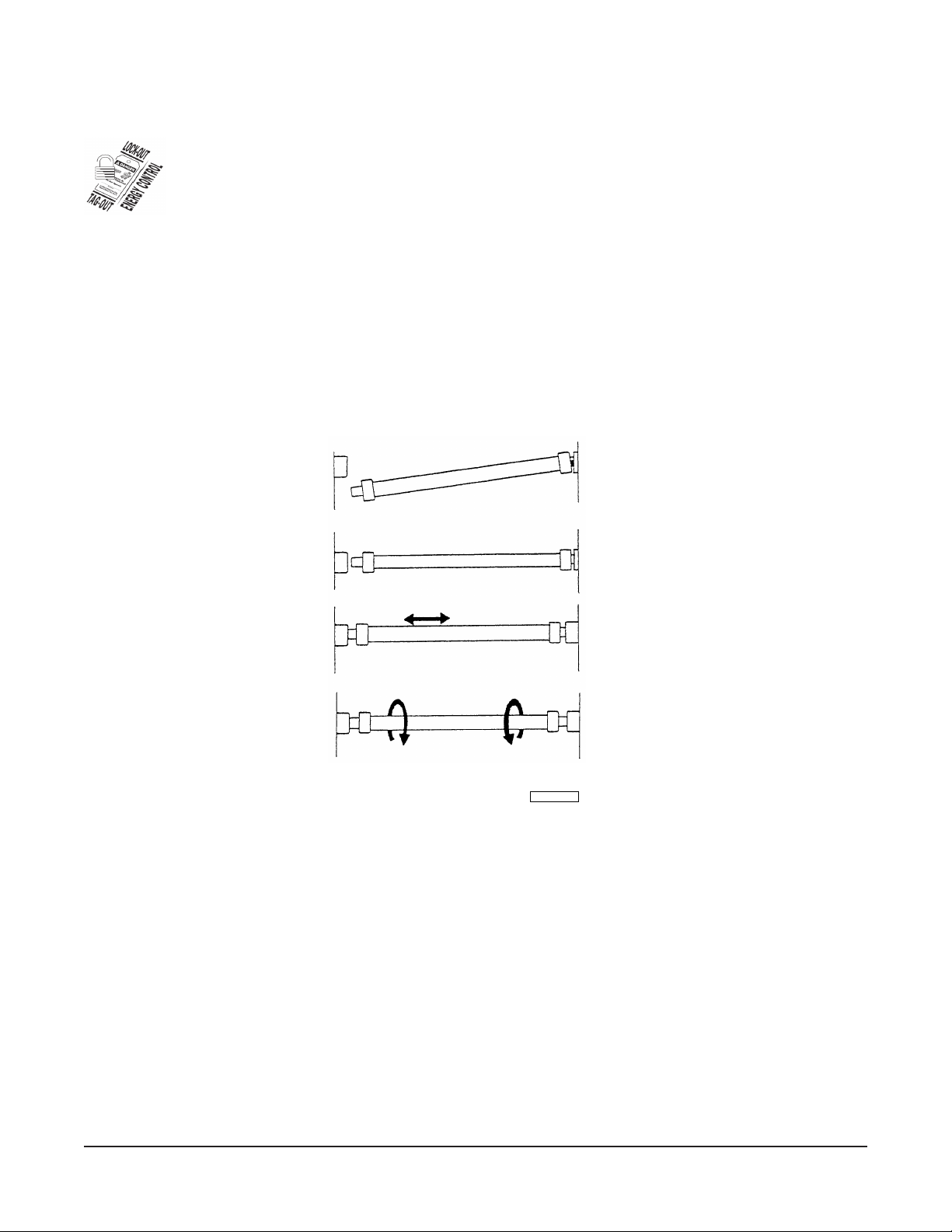
HEATER (Fig. 1)
1. Push one end of the heater into one socket as far as it will go.
2. Swing the other end of heater up until it lines up with the opposite socket.
3. Release heater and it will snap into place.
4. Grasp the heater and move it back and forth to ensure that it is centered correctly.
5. Rotate the heater clockwise, then counterclockwise, to ensure that it is seated correctly.
PL-53526-E
Fig. 1
COOLING FANS
1. Remove the access panel on the left side of the cheesemelter.
2. Unscrew the four mounting screws.
3. Disconnect the fan leads and lift out the fan.
4. Install new fan.
• Make sure that all wires are enclosed by the nylon wire clamps so that none of the wires
can reach the fan blades.
The cooling fan should blow air into the control compartment. An arrow on the fan housing indicates
the direction of air flow.
– 2 –
Page 3

COMPONENT REPLACEMENT
1. Remove the access panel on the left side.
2. Remove all screws holding down the cover.
3. Lift cover straight up.
Replacement of the voltage regulator, actuating switch, main terminal block, or the contactor (1048
only) will require removing the component mounting plate.
1. Disconnect the wires from the on pilot light and the switches.
2. Tag or mark the wires to ensure correct replacement.
3. Remove the two mounting screws.
• One is located at the bottom left of the voltage regulator.
• The other is located under the lower part of the cooling fan. This screw can be reached
through the blades of the fan.
4. Remove the component mounting plate and replace the component. Make sure that the screw
that operates the actuating switch is above the switch lever.
– 3 –
Page 4

COMPONENT LOCATION DRAWING
CONTACTOR
(1048)
VOLTAGE
REGULATOR
MOUNTING PLATE
COMPONENT
SOCKETS
PILOT
LIGHT
SWITCH
TERMINAL
BLOCK
GROUND STUD
COMPONENT LOCATION (VIEW OF LEFT SIDE WITH COVER REMOVED)
NYLON
LOOP
COOLING
FAN
– 4 –
ACTUATING
SWITCH
PL-53527
Page 5

TROUBLESHOOTING
(See component location drawing on page 4.)
WARNING: DISCONNECT THE ELECTRICAL POWER TO THE MACHINE AND
FOLLOW THE LOCKOUT / TAGOUT PROCEDURES.
IF THE UNIT BLOWS A FUSE OR TRIPS A CIRCUIT BREAKER
1. Check the capacity of the circuit.
2. Short circuits may be accompanied by sputtering sounds or sparks.
IF THE HEATERS DO NOT LIGHT
1. If the pilot light does not come on, and the cooling fan does not run, check for a blown fuse or
an open circuit breaker.
2. Check for failure of the main switch.
3. On the 1048, check for contactor failure.
4. Check for a loose wiring connection.
5. If the pilot light is lit, and the cooling fan is running, but the heaters do not light, check for loose
wiring connections. When the cheesemelter is operating in standby with no product on the rack,
the heaters may not glow, but will still emit some heat.
6. If one heater is lit, but the other is not, a burnout or a loose connection is the probable cause. Also,
check that the heater is properly seated in its socket.
IF THE COOLING FAN DOES NOT RUN
1. If the pilot light is not lit, and the heaters do not light, check for a blown fuse or open circuit breaker.
2. If the pilot light is lit and the heaters function, the probable cause is a loose connection.
IF THE HEATERS DO NOT COME UP TO FULL HEAT WHEN THE PRODUCT IS PLACED ON THE
RACK
1. Be sure that the product is on the front half of the rack. The rack is balanced to trip the actuating
switch, but the weight must be on the front half of the rack to ensure that it does so.
2. Check that the rack is at the same level on both sides and is correctly inserted.
3. If the rack operates freely, the failure of the actuating switch is the probable cause.
– 5 –
Page 6

ELECTRICAL SCHEMATIC 1024 & 1036
HEATERS
VOLTAGE
REGULATOR
TERMINAL
BLOCK
PILOT
ACTUATING
SWITCH
FAN
LIGHT
MAIN
SWITCH
PL-53528
GROUND
LUG
– 6 –
Page 7

ELECTRICAL SCHEMATIC 1048
LEFT SIDE HEATERS RIGHT SIDE HEATERS
VOLTAGE
REGULATOR
ACTUATING SWITCH
LEFT
PILOT
LIGHT
LEFT
SWITCH
RIGHT
PILOT
LIGHT
RIGHT
SWITCH
FAN
MAIN
PILOT
LIGHT
CONTACTOR
1048
SCHEMATIC
PL-53529
MAIN SWITCH
TERMINAL
BLOCK
GROUND STUD
– 7 –
Page 8

ITEM DESCRIPTION PART NUMBER
NO.
1024 1036 1048
1 Heater (208V) 825536 825331 825300 (1050w)
2 Heater (240V) 825538 825332 825301 (1050w)
3 Heater Socket 825098 825098 825098
4 Pilot Light 825100 825100 825100
5 Main Switch 825100-10 825100-10 825100-10
6 Left/Right Heat Switch — — 825100-10
7 Contactor — — 825126-10
8 Terminal Block 825126-40 825126-40 825126-40
9 Voltage Regulator 825128-90 825128-90 825128-90
10 Cooling Fan 825100-80 825100-80 825100-80
11 Fan Guard 825100-50 825100-50 825100-50
12 Actuating Switch 825150-90 825150-90 825150-90
13 Counter Leg—Thermoplastic 825172-50 825172-50 825172-50
14 Rack 825168-20 825172-10 825168-30
15 Outside Cover Mounting Screws SC-066-21 SC-066-21 SC-066-20
16 Heat Shield/Deflector 825083 825083-10 825083 (2)
17 Ceramic Wire Nuts FE-009-34 FE-009-34 FE-009-34
18 Rack Stop 825072 825072 825072
19 Access/Control Box Cover 825195 825195 825195
20 Access Panel Screws SC-053-38 SC-053-38 SC-053-38
21 LH Pivot (2 Position) 825196 — —
22 RH Pivot (2 Position) 825199 — —
23 LH Pivot (4 Position) 825071 825071 825071
24 RH Pivot (4 Position) 825071-10 825071-10 825071-10
25 Switch - Slide (2 Slots) 825198 825198 825198
26 Switch - Slide (4 Slots) 825073 825073 825073
27 Slide Bracket 825073 825073 825073
28 Nut NS-011-18 NS-011-18 NS-011-18
29 Screw SC-119-65 SC-119-65 SC-119-65
30 Screw SC-119-23 SC119-23 SC-119-23
31 Washer WS-002-25 WS-002-25 WS-002-25
32 Lockwasher WL-014-07 WL-014-07 WL-014-07
33 Lockwasher WL-006-07 WL-006-07 WL-006-07
34 Legs—Metal 804405 804405 804405
– 8 –
Page 9

RECOMMENDED SPARE PARTS LIST
PART
NO. DESCRIPTION AMT.
825536 Heater (208V) 1024 .................................................................................................... 2
825331 Heater (208V) 1036 .................................................................................................... 2
825300 Heater (208V) 1048 .................................................................................................... 2
825538 Heater (240V) 1024 .................................................................................................... 2
825332 Heater (240V) 1036 .................................................................................................... 2
825301 Heater (240V) 1048 .................................................................................................... 2
825098 Heater Socket ............................................................................................................. 2
825100-10 Main Switch ................................................................................................................ 2
825126-10 Contactor, 1048 .......................................................................................................... 2
825128-90 Voltage Regulator ....................................................................................................... 2
825100-80 Cooling Fan ................................................................................................................ 2
825150-90 Actuating Switch ......................................................................................................... 2
– 9 –
FORM 31087 Rev. B (06-06)
 Loading...