

Page 1

SERVICE AND
PARTS MANUAL
SIGNATURE SERIES
MODEL MODEL MODEL
OVEN STD IGNIT ML-044905 VSB36IR ML-044936 VIR35M ML-044961
STD OVEN ML-044906 ML-044937 VIR36FM ML-044962
CONV OVEN ML-044907 VRBS48 ML-044938 VCB25M ML-044963
VCB25S ML-044908 VRBS60 ML-044939 VCB36M ML-044964
VCB36S ML-044909 VRBS72 ML-044940 VCB47M ML-044965
VCB47S ML-044910 VRBS96 ML-044941 VCB36 ML-044966
VGF18 ML-044911 VRBR36 ML-044942 VCB36C ML-044967
VS12T ML-044912 VRBR48 ML-044943 ML-044968
VS12F ML-044913 VRBR60 ML-044944 ML-044969
VS18T ML-044914 VRBR72 ML-044945 VO236 ML-044970
VS18F ML-044915 VRBR96 ML-044946 ML-044971
VS24T ML-044916 VIR36 ML-044947 ML-044972
VS24F ML-044917 VIR36C ML-044948 ML-044973
VS36T ML-044918 VIR36S ML-044949 ML-044974
VS36F ML-044919 VIR36F ML-044950 ML-044975
VS12S ML-044920 VIR36FC ML-044951 ML-044976
VS18S ML-044921 VIR36FS ML-044952 ML-044977
VS24S ML-044922 VRB36 ML-044953 ML-044978
VS36S ML-044923 VRB36C ML-044954 ML-044979
VS12M ML-044924 VRB36S ML-044955 VCM24R ML-135124
VS18M ML-044925 VRB36F ML-044956 VCM36R ML-135126
VS24M ML-044926 VRB36FC ML-044957 VCM48R ML-135127
VS36M ML-044927 VRB36FS ML-044958 VCM60R ML-135128
VFM18 ML-044928 VRB36M ML-044959 VCM72R ML-135129
VSB36R ML-044935 VRB36FM ML-044960 VCM84R ML-135130
IMPORTANT FOR YOUR SAFETY
THIS MANUAL IS PREPARED FOR THE USE OF TRAINED VULCAN SERVICE TECHNICIANS
AND SHOULD NOT BE USED BY THOSE NOT PROPERLY QUALIFIED. IF YOU HAVE ATTENDED
A VULCAN SERVICE SCHOOL FOR THIS PRODUCT, YOU MAY BE QUALIFIED TO PERFORM
ALL PROCEDURES DESCRIBED IN THIS MANUAL.
THIS MANUAL IS NOT INTENDED TO BE ALL ENCOMPASSING. IF YOU HAVE NOT ATTENDED
A VULCAN SERVICE SCHOOL FOR THIS PRODUCT, YOU SHOULD READ, IN ITS ENTIRETY,
THE REPAIR PROCEDURE YOU WISH TO PERFORM TO DETERMINE IF YOU HAVE THE
NECESSARY TOOLS, INSTRUMENTS AND SKILLS REQUIRED TO PERFORM THE
PROCEDURE. PROCEDURES FOR WHICH YOU DO NOT HAVE THE NECESSARY TOOLS,
INSTRUMENTS AND SKILLS SHOULD BE PERFORMED BY A TRAINED VULCAN SERVICE
TECHNICIAN.
REPRODUCTION OR OTHER USE OF THIS MANUAL, WITHOUT THE EXPRESS WRITTEN
CONSENT OF VULCAN-HART COMPANY IS PROHIBITED.
VULCAN-HART COMPANY, P.O. BOX 696, LOUISVILLE, KY 40201-0696, TEL. (502) 778-2791
– 1 –
FORM 31203 Rev. A (March 2002)
Page 2

– 2 –© VULCAN-HART COMPANY, 2002
Page 3

TABLE OF CONTENTS
INTRODUCTION .................................................................................................................................................... 4
Service Notes ........................................................................................................................................... 4
Product Features and Descriptions .......................................................................................................... 4
UNCRATING/SETUP ............................................................................................................................................. 6
INSTALLATION REQUIREMENTS ....................................................................................................................... 6
GAS CONNECTIONS ............................................................................................................................................ 7
GAS PRESSURE REQUIREMENTS .................................................................................................................... 7
GAS PRESSURE CHECK PROCEDURES .......................................................................................................... 8
Steps ......................................................................................................................................................... 8
VENTILATION REQUIREMENTS ......................................................................................................................... 9
PILOT ADJUSTMENTS........................................................................................................................................10
BURNER ADJUSTMENTS ...................................................................................................................................10
BATTERY INSTALLATION ..................................................................................................................................12
THERMOSTATS ...................................................................................................................................................15
CALIBRATION OF THERMOSTATS ...................................................................................................................16
Standard Oven with FDTO Thermostat ...................................................................................................16
Snorkel Oven and/or Electric Ignition Oven with KX Thermostat ..........................................................17
Griddles with BJWA Thermostat .............................................................................................................18
OVEN ELECTRIC IGNITION SYSTEMS .............................................................................................................20
Spark System ..........................................................................................................................................20
BRASS VALVES ..................................................................................................................................................24
DOORS, DOOR SEAL, HINGES AND COUNTERWEIGHTS .............................................................................25
Door Removal/Counterweight Replacement ............................................................................................25
CLEANING PROCEDURES ..................................................................................................................................27
Cleaning Tips ...........................................................................................................................................28
SCHEDULED MAINTENANCE .............................................................................................................................29
Recommended Service Frequency .........................................................................................................29
Inspection Items ......................................................................................................................................29
TROUBLESHOOTING ..........................................................................................................................................30
PARTS ..................................................................................................................................................................35
– 3 –
Page 4

INTRODUCTION
Service Notes
The information in this manual is not intended to be all inclusive, rather it is a guide to the applications,
specifications and requirements of the Vulcan-Hart appliance.
Vulcan-Hart appliances are not any different in concept, components or application than many other appliances.
Vulcan-Hart appliances are designed to provide years of high performance. It is imperative that the installation
requirements, operating guidelines and maintenance procedures be followed to ensure long life and maximum
performance.
If the installation and/or appliance has not met the requirements outlined in this manual, please notify the VulcanHart Company, the end user and all other parties involved.
Product Features and Descriptions
The Signature Series Range line is an extra heavy-duty product, commonly referred to as hotel and/or institutional
cooking equipment.
The gas line is a 1
1
/4" front manifold, battery-type appliance. Chassis come in a variety of widths: 12", 18", 24"
and 36".
Top configurations available:
• Open burners in 12" and 18" sections
• Cast-iron hot tops in 12" and 18" sections
• Manual and thermostat griddles in 12" increments
• Graduated hot top (French top)
Standard and convection ovens are available on 36" chassis only.
On the 12", 18" and 24" chassis, the base of the oven is called a skeleton which is an open storage compartment.
The third configuration is a modular unit. It has a top section without a base and is mounted to an angle iron base
with 1 1/4" pipe legs.
OPEN BURNERS - The standard burner comes rated at 30,000 BTU/hr with a four slot, lift-off burner cap. There
are four other types of burner caps available. The no-slot types are used for large diameter cookware. There are
8-, 12- and 16-slot caps for direct centered heat used in sauté applications.
HOT TOPS - Full hot tops are rated at 35,000 BTU/hr and are available in 12" and 18" widths. Half hot tops (rear
only) are rated at 17,500 BTU/hr and are also available in 12" and 18" widths.
GRADUATED HOT TOPS - (French Top) This configuration is rated at a total of 50,000 BTU/hr. The large burner
is rated at 25,000 BTU/hr. The medium burner is rated at 14,000 BTU/hr and the small burner is rated at 11,000
BTU/hr.
GRIDDLES - Rated at 30,000 BTU/hr per burner. Manual control is standard. BJWA modulating thermostats are
available. Griddles are in 12" increments with one manual valve or thermostat per 12" section.
STANDARD OVEN - Rated at 40,000 BTU/hr. The interior dimension is 27" wide x 28 1/2" deep x 14 1/2"
high and
is supplied with one oven rack. The rack guides have four positions. The door is counterbalanced. The thermostat
is a modulating FDTO type with a temperature range of 250°F to 500°F degrees.
– 4 –
Page 5

Product Features and Descriptions (Cont.)
1
SNORKEL CONVECTION OVEN - Rated at 30,000 BTU/hr. The interior dimension is 26
/4" wide x 23” deep and
14" high. The oven cavity is fully porcelainized. The door is also counterbalanced. Three oven racks are supplied
and the rack guides have four positions. The thermostat is a “snap action” KX type with a temperature range of
200°F to 500°F degrees. There is a 1/4 HP fan motor that requires 115 Volt minimum 15 amp service.
LEGS/CASTERS - Standard units are supplied with four 6" legs. For curb installation, leveling bolts are available.
Casters are available with 3" or 5" diameter wheels. Legs, casters or curb bolts are all 5/8" x 11 stems.
BACK RISERS - The standard unit is equipped with a 6" stainless steel stub riser. Also available are single and
double-deck risers with or without shelves and reenforced high shelves capable of mounting a Cheesemelter or
Salamander broiler. Another option is 48", 60" and 72" back risers in the same configurations capable of spanning
more than one unit. These wider back risers are special order only. All back risers are attached to the units via
a 2" x 4" female receiver on the top rear of the chassis and all high shelves/stub risers are interchangeable.
EXTERIOR FINISHES - The standard finish is black powder coat paint. All chassis’s are powder coated prior to
assembly. The most common exterior finish is stainless steel on the front. Stainless steel sides are available as
an option. Cast-iron open burners and grates are painted with a light coat of water based enamel. The water-based
enamel is intended to protect the raw cast iron during transit and storage only. Cast iron hot tops and steel griddle
plates are coated with a USDA-approved oil that must be removed prior to operation.
SPREADERS - These are non-functional items that are designed to offer a work surface between appliances and/
or a place to locate a pressure regulator in a battery line up. The standard spreader comes with the continuous gas
manifold, back riser and a top surface only. A front apron is available.
GAS CONNECTIONS - The standard unit is supplied with a 1
1
/4" front manifold with a male union fitting on the
left side of the appliance, and the female union fitting is on the right side of the appliance. As an option, a rear gas
tailpipe connection is available in either 1 1/4" or 3/4". Also this rear gas connection can be used to interconnect a
cheese melter or salamander broiler that is mounted to the re-enforced high shelf. Manifold caps and cover plates
are available for stand-alone units or battery end units.
MISCELLANEOUS and SPECIALS - There are many other configurations available in the Signature line including
models for back-to-back island installations. Special wide and/or long bull noses to span up to 108" in length and
8 3/4" in width. Additionally, back risers can be special ordered to span up to 72" in width.
Whenever dealing with any unit or configuration that seems unfamiliar, always secure the serial numbers and relay
that information to the factory for the specifics of the appliance.
Also available in the Signature line are double-stacked standard ovens, fryers, pasta cookers, single and doubledeck top-fired broilers and refrigerated bases. Only Vulcan-Hart Cheesemelters and Salamander broilers can be
mounted to the Signature line.
– 5 –
Page 6

UNCRATING/SETUP
All Vulcan-Hart appliances are inspected and tested for function before leaving the factory. The transportation
company assumes responsibility for safe delivery of the shipment. Should an appliance arrive with apparent and/
or hidden damage, see the freight damage section of this manual.
• Uncrate the appliance; carefully remove all tie-down straps and packing material.
• Locate and identify any and all loose pieces such as oven racks, rack guides, casters, legs, pressure
regulator, back shelves and owner's manual.
• Locate the rating plate and check the specifications (gas type/electrical). If they do not match the utility
connections, do not proceed with the installation. Contact the dealer and/or Vulcan-Hart Customer Service.
• Note the model and serial number of the appliances and retain for future reference.
• Place the appliance in the proximity of its final location, install legs/casters and then inspect gas
connection points for obstructions and/or debris.
• Place the unit in its final location. Using a carpenter’s level, on the oven bottom or a solid portion of the
chassis, check the appliance to ensure it is level from side to side and front to back. Using the bullet foot,
level as necessary.
• For multiple unit installations (battery installations) see the battery installation section of this manual.
• Casters are non-leveling. If the floor is more than
1
/8" out of level, it is recommended that casters not be
used.
INSTALLATION REQUIREMENTS
The installation must allow for adequate clearances for service and operation with a minimum of 36" in front of the
appliance.
Models with 30,000 BTU burners must maintain 20" on the left and right sides as well as 2" in the rear to combustible
materials. The older models with 20,000 BTU burners require 6" on the left and right sides as well as 2" in the rear
to combustible materials. For non-combustible locations the clearances, are 0" left, right and rear.
Snorkel convection oven models require additional clearances in the rear for the fan motor to be able to cool itself,
with a minimum of 2". When snorkel ovens are mounted on curbs and/or without legs, there must be at least 6"
of airspace behind the appliance.
There must be an adequate supply of fresh air, based on BTU consumption and exhaust volume to ensure proper
combustion as well as maximum performance.
The appliance or line up must be installed so the flow of combusted air/flue gasses are not obstructed or disturbed
in any way. Make up air, fans or drafts directed at the rear of the appliance will obstruct, inhibit or disturb the flow
of flue gasses. This will affect the oven and/or griddle performance, cause poor combustion and can damage the
operating components, which will void the appliance warranty. Do not place wall mounted objects over the
appliance.
Wall-mounted objects, appliances or shelves above the appliance will block the natural path of the flue gasses,
which can slow or stop the appliance from fluing. This will cause problems and damage to operating components,
which will void the appliance warranty.
Make up air, fans or drafts directed at the top or front of the appliance will cause problems with open burners, such
as delayed ignition and poor performance.
– 6 –
Page 7

Installation Requirements (Cont.)
All appliances must be vented to the outside. Depending on local codes, the specifics may vary. Check with local
authorities. Fluing occurs because heat rises vertically, which has no force behind it. Any obstruction or
disturbance will negatively affect the appliances ability to flue itself. Make up or fresh air should be present low
and in the front of the appliance.
Gas connector hoses shall be commercial grade and have the capability of supplying at least 10% more fuel than
the maximum BTU consumption of the appliance or line up. Furthermore, gas connector hoses shall be no smaller
than 3/4" inside diameter.
When units are mounted on casters, the gas connector hose must comply with the current standard for movable
gas appliances. Furthermore, the installation must provide for a restraining cable/chain device to limit the
movement of the appliance or line up.
GAS CONNECTIONS
CAUTION: ON ALL GAS SUPPLY CONNECTIONS ANY PIPE JOINT COMPOUND USED MUST BE RESISTANT
TO THE PROPERTIES OF PROPANE (LP) GAS.
Before making any gas connections, be sure to check for obstructions or debris in the manifold pipe and union
fitting. Once the appliance has been connected and the air has been purged from the system all the fittings and
connections must be tested for leaks using a soap solution, or an appropriate gas leak-sensing instrument.
WARNING: DO NOT USE AN OPEN FLAME TO CHECK FOR GAS LEAKS.
If a gas leak is detected and cannot be stopped, shut off gas supply to the appliance or line up and contact your
local gas provider or an Authorized Servicer.
GAS PRESSURE REQUIREMENTS
Natural gas pressure should be 5" Water Column (W.C.) plus or minus 1/2" W.C.
Propane (LP) gas pressure should be 10" W.C. plus or minus 1/2" W.C.
On units that have infra-red burners such as Salamanders and Cheesemelters, the gas pressure variables are
slightly different, plus 1/2" W.C. minus .2" W.C. Example: on natural gas, 4.8" to 5.5" W.C., on propane (LP) 9.8"
to 10.5" W.C.
All gas appliances must have a gas pressure regulator installed. In order for the pressure regulator to perform
properly, the supply pressure must be greater than the operating pressure. For example, most cities supply 7" to
9" W.C. of natural gas pressure to a building.
Propane (LP) systems should supply 11" to 12" W.C. The appropriate pressure regulator will provide the correct
pressure to the unit or line up.
Sometimes even though the gas pressure is correct, the appliance may not be able to function properly because
the gas supply piping may be too small and is not able to supply the volume of gas required. It is recommended
that the piping be able to supply a minimum of 10% more fuel than the maximum BTU consumption of the appliance
or line up.
Because of the size of the Signature manifold (1 1/4") when a 1 1/4" pressure regulator is used, up to three appliances
may be connected to one pressure regulator. For example, a battery line up of six units must be connected to two
gas pressure regulators. A single appliance can be connected to a 3/4" gas pressure regulator.
– 7 –
Page 8

GAS PRESSURE CHECK PROCEDURES
Steps
1. Connect the manometer to the main gas manifold pipe of the appliance, or in a battery the center unit of
the line up. If the pressure reading is taken at the oven burner or anywhere other than the main gas manifold
pipe, the pressure drop can be 1" W.C. or greater and the test is invalid.
2. Fire up one burner and take a reading.
3. Fire up all the burners on the appliance and take a reading.
4. Fire up all the gas appliances on that supply line and take a reading.
5. At no time should the pressure drop more than 1/2" W.C.
If the pressure is set at the recommended setting and the pressure drop is slightly under, or 1/2" W.C., the regulator
can be adjusted up to the maximum, for example, a 5.5" W.C. for natural and 10.5" W.C. for propane (LP). However,
if the pressure drop is greater than 1/2" W.C., it is likely a lack of volume due to too small of a supply line. Check
with the gas provider for the proper size gas line.
– 8 –
Page 9

VENTILATION REQUIREMENTS
Depending on local codes, ventilation requirements may vary. A basic formula is as follows: 100 to 150 CFM (cubic
feet per minute) per square foot of floor space that the appliance or line up occupies. For example, one standard
six burner unit, which measures 36" wide by 38" deep, equals approximately 9 square feet of floor space, therefore
900 to 1,350 CFM of exhaust is required.
Units with charbroilers may require more CFM exhaust; check with local authorities.
The hood should extend a minimum of 6" over all exposed sides of an appliance or line up. Seldom can the units
be without rear clearance, so figure 4" in the rear.
For every cubic foot of gas that is burned, 11 cubic feet of by-products are produced. These by-products must be
vented to the outside.
Ventilation systems need to be properly balanced to ensure that all the by-products are exhausted. There must
be an adequate supply of fresh air for proper combustion and still a very slight negative pressure in the kitchen.
Sometimes a hood system will be operating perfectly as per its manufacturer’s specifications, however there is
still a problem with the gas-cooking appliance. The hood system may not be compatible with the gas appliance
under it. In these instances, the service contractor for the hood system and the appliance Servicer will have to
work together to attempt to correct the problem. If it is determined that the hood system is not compatible with
the appliances under it, it is imperative that this information be communicated to the end user, the dealer and all
parties involved, especially the Vulcan-Hart Company.
If the fresh air system (make up air) is such that ovens and griddles are experiencing fluing problems, there will
be component failures due to excessive heat. If the open burners are fluttering or blowing around due to make up
air being directed at the top or front of the unit delayed, no ignition will occur, and the appliance’s performance will
be severely affected. If it is determined that any of these conditions exist, the appliance warranty will be voided.
Some cities allow the use of a direct vent system in lieu of a motor-driven exhaust system to vent a bake oven.
Check with local authorities.
To increase appliance performance and minimize energy consumption of the ventilation system:
• Add side panels on canopy hoods.
• Avoid make up air diffusers close to hood or re direct air away from top and/or rear of appliance.
• Add multi-or variable-speed exhaust and make up air fan controls.
– 9 –
Page 10
PILOT ADJUSTMENTS
After all connections/fittings have been checked for gas leaks and no leaks are found, the pilots can be lit. Locate
each pilot and the corresponding pilot adjustment valve. Light the pilots and adjust them up or down as necessary.
The flame should be only high enough to ignite the corresponding burner within 3 or 4 seconds maximum.
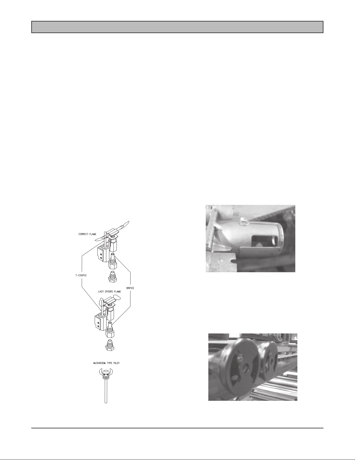
Mushroom head-type pilots are used on open burners, griddles and hot tops. The flame should be only about the
size of a dime. This type of pilot will burn yellow; that is the reason they should be as small as possible and still
be able to ignite the burner, within 3 or 4 seconds, maximum (Diagram #2).
Orifice pilots with thermocouples or flame switches are used on ovens. The flame should be large enough to
completely engulf the tip of the thermocouple/sensor and make the tip of the thermocouple/sensor glow red-hot.
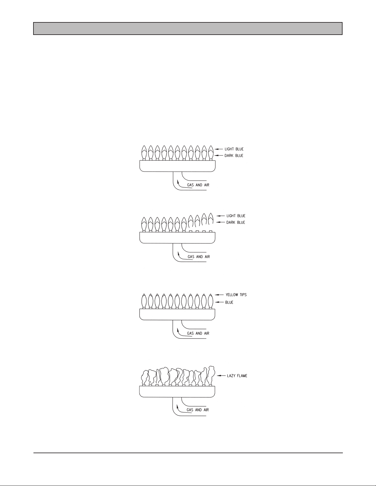
Orifice pilot flames should be sharp, well-defined, two-tone blue when burning natural gas. However, when burning
propane (LP) there may be a tiny yellow tip to the flame. This yellow tip should be no more than 10% of the total
flame size (Diagram #1).
All gas burners should ignite within 3 to 4 seconds, maximum. All burners are tested at the factory prior to shipment.
However, fine tuning adjustments may be necessary to accomplish 3 to 4-second ignition at the installation site.
Most gas burners have an air shutter. There are two types of air shutters, the cap or disk type (Diagram #3) and
the sleeve type (Diagram #4). The cap or disk type is used on burners with cast iron venturis. The sleeve type is
used on tubular steel burners and/or burners with tubular steel venturis. All burners are tested and the air shutters
are set at the factory prior to shipment. However the factory cannnot make the fine tuning adjustments that may
be necessary at the actual installation.
DIAGRAM #1
DIAGRAM #3
DIAGRAM #2
DIAGRAM #4
– 10 –
Page 11
BURNER ADJUSTMENTS
When using natural gas, the air shutter will be approximately 50% open. On propane (LP) the air shutter will be
approximately 90% open.
If the flame is soft, lazy or yellow, there is not enough primary air and the air shutter needs to be opened up. In
the event this does not solve the situation, check the burner for obstructions and clear as necessary. If the flame
is lifting off the burner, there is too much primary air and the air shutter needs to be closed down (Diagram #5).
If grates, hot tops or oven bottoms have been removed, be sure to recheck flame adjustments with these items
in place as the flame characteristics may change and additional adjustments may be necessary. Always recheck
burner flames after the grates, hot tops and oven bottoms are in their proper place.
DIAGRAM #5
– 11 –
Page 12

BATTERY INSTALLATION
1. Remove grates, hot tops, knobs, front manifold cover and bull nose (Diagram #6).
2. Slide open burners and/or hot tops off the orifice/valve, but do not remove them from burner box. It is not
necessary to remove griddle burners unless the griddle plate is already off the unit. Be careful that the
weight of the griddle burner or burners does not cause the manifold pipe to rotate when the manifold
mounting clamps are loosened.
3. Loosen manifold mounting clamps enough that the manifold pipe is free to move (Diagram #7).
4. Slide units together and level with bullet feet, as necessary, so that the manifold pipes mate up. If the pipes
do not mate up, the units are not level. Do not use the manifold mounting clamps to compensate for
anything other than very minor adjustments (1/8" or less). Units on casters will not level up if floor is not
level. Casters must be installed wrench tight.
3. Engage the union nut with the opposing male union fitting and hand-tighten as much as possible until units
are mated up (Diagram #7).
4. Locate mounting holes in the riser and top frame, then bolt the units together using the appropriate length
1
/4" bolts (Diagram #8 on page14).
5. When all the units in the battery are connected, use a backup wrench on the manifold pipe to begin
tightening the unions.
CAUTION: DO NOT ALLOW THE MAIN MANIFOLD PIPE TO ROTATE, AS THIS WILL DAMAGE THE
PILOT LINES AND/OR VALVES AND MAY CAUSE GAS LEAKS.
6. Once all the units are bolted together and the unions are tight make sure all the valves are in the original
level position. Retighten the manifold pipe mounting clamps.
7. Reinstall and bolt bull noses together (Diagram #6).
8. Reinstall any burners that were removed. Reattach the pilots that were removed. Check that burners and/
or pilot lines and fittings are in their original position and have not been damaged.
9. Install pressure regulators as needed. No more than three units are to be connected to any one,11/4" gas
pressure regulator.
10. Connect battery to gas supply. Purge the air from the system. Check for leaks using a soap solution.
WARNING: DO NOT USE AN OPEN FLAME TO CHECK FOR GAS LEAKS.
11. Check and adjust gas pressure if necessary (see gas pressure adjustment and gas pressure check
sections of this manual).
12. Thoroughly check all units for packing material, protective coatings and manuals before lighting any pilots.
13. Begin lighting and adjusting pilot flames (see pilot adjustment section of this manual).
14. Check and adjust all burners as necessary (see burner adjustment section of this manual). All burners
should light within 3 or 4 seconds, maximum. It may be necessary to remove grates, hot tops, oven
bottoms and possibly the griddle plate to make the necessary adjustments.
15. At this point if no problems are noted the battery is ready to be started up. If any problems are noted they
must be corrected before the battery can be put into operation. AN AUTHORIZED SERVICER MUST
MAKE ALL REPAIRS to ensure the factory warranty is not compromised.
– 12 –
Page 13
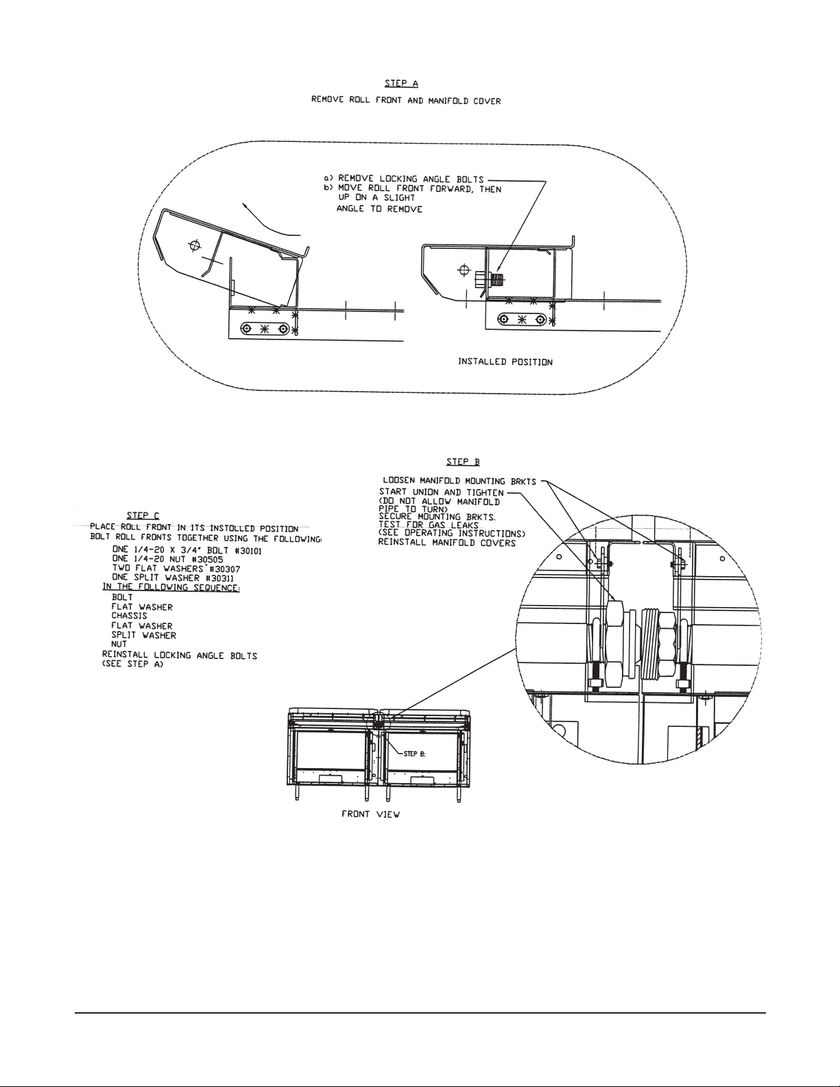
DIAGRAM #6
DIAGRAM #7
– 13 –
Page 14
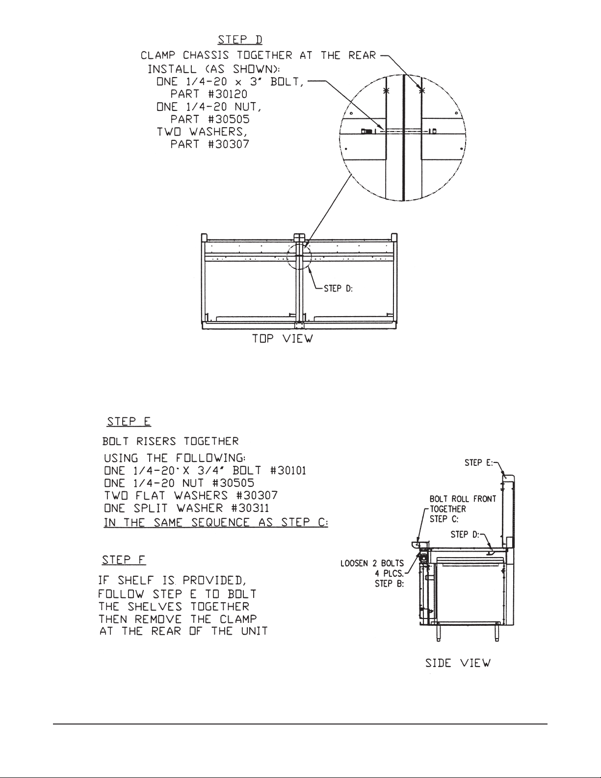
DIAGRAM #8
– 14 –
Page 15

THERMOSTATS
The standard oven uses an FDTO-type, modulating thermostat. When first turned on, the flame comes on full
speed, approximately 1 1/4" to 1 1/2" tall. As the temperature approaches the set point, the flame slowly reduces
in size. When the temperature is achieved, the flame should be in bypass, approximately 1/8" tall. The bypass flame
will keep the oven temperature constant unless the door is opened and heat is lost.
When the oven needs to recover heat loss, the thermostat will allow the flame to slowly increase in size until the
temperature is again at the set point. Usually the thermostat does not require calibration, however it may need to
have the bypass flame set at the time of installation. The temperature accuracy of this thermostat is 25°F. For
calibration and/or bypass adjustment, see thermostat calibration section of this manual.
Snorkel and electric ignition ovens use a KX-type snap action thermostat. When first turned on, the flame comes
on full speed. When it achieves the set temperature, it shuts off. When 10°F to 15°F is lost, the thermostat will
come on full speed to recover the heat loss. Due to the fact the thermostat shuts completely off and the oven is
constantly venting heat off through the flue, the thermostat will cycle on and off throughout the cooking process.
The temperature accuracy of the KX thermostat is 15°F to 20°F. If calibration is required, see the calibration section
of this manual.
The thermostat used on griddles is a BJWA modulation type. When first turned on the flame comes on full speed,
approximately 3/4" to 1" tall. As the temperature approaches the set point, the flame is slowly reducing in size. When
the temperature is achieved, the flame should be in bypass. Bypass flame for griddles should only be big enough
to keep the burner lit all the way around, with little blue dots of flame.
This type of thermostat by design will allow the temperature to creep if the griddle is left idling, with no product
on the griddle, for a minimum of 50°F an hour. Therefore it is imperative that the bypass flame be correct. If the
bypass flame is not correct, the temperature will creep to 100°F to 200°F an hour. Temperature accuracy of the
BJWA thermostat is 25°F. For calibration/bypass adjustments see the calibration section of this manual.
NOTE: Calibrations and/or bypass adjustments require a good working knowledge of the components and system
as well as specific test instruments and should only be performed by authorized service personnel. When checking
calibrations on the BJWA griddle thermostat, it is necessary to begin the procedure when the griddle is cold.
Attempting to calibrate the BJWA griddle thermostat from other than a cold start is extremely difficult, as well as
time consuming, and can cause the temperature to be incorrect at a later time.
– 15 –
Page 16
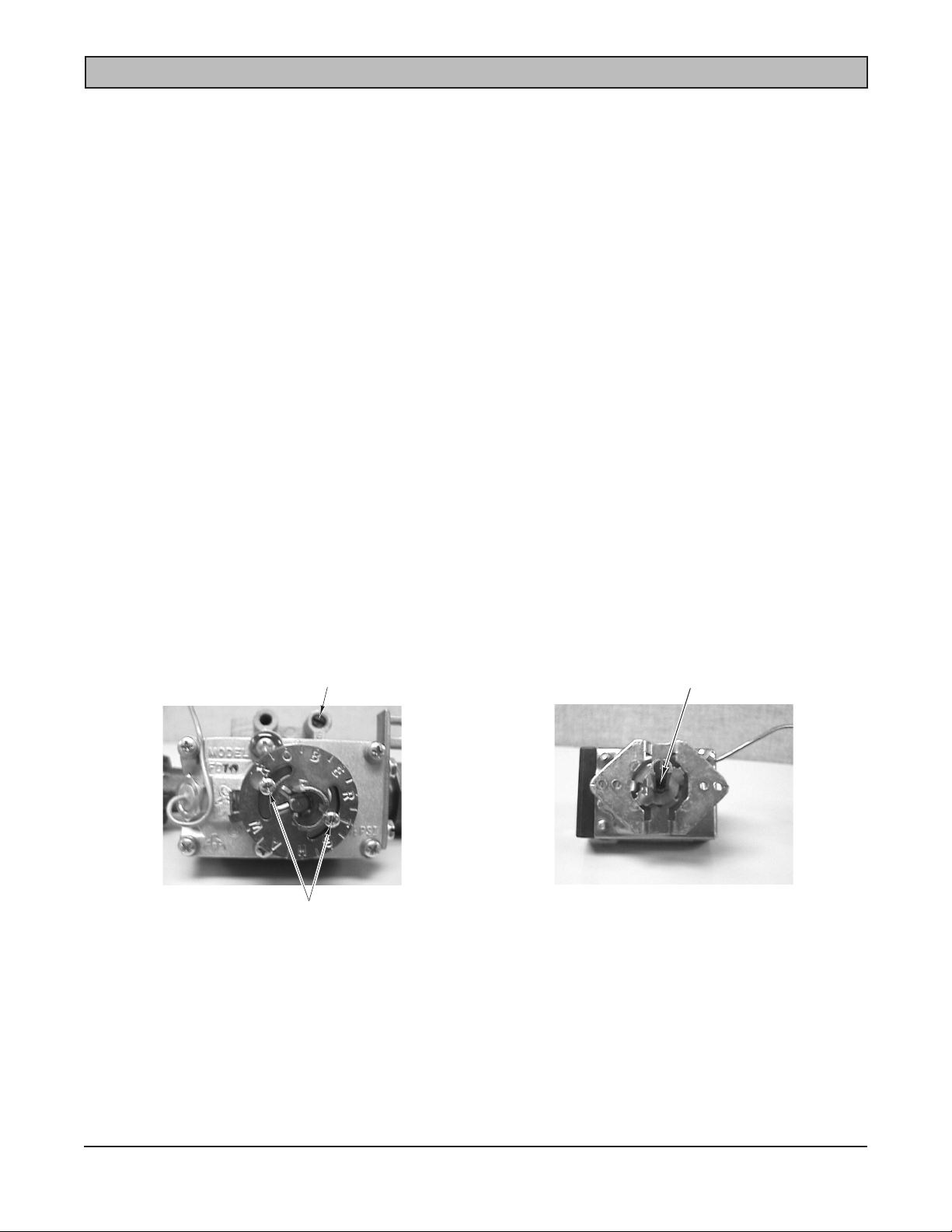
CALIBRATION OF THERMOSTATS
Field recalibration is very seldom necessary on new appliances, however older thermostats may require
calibration. Recaibration should only be considered when cooking results definitely indicate the thermostat is not
maintaining the set temperature. Before attempting recalibration, the temperature should should be checked with
temperature test instrument or a reliable thermometer.
Standard Oven with FDTO Thermostat
1. Place the test instrument sensor or thermometer in the center of the oven cavity and close the door.
2. Turn oven on, set the thermostat dial to 300 degrees and allow the oven to cycle several times (at least
20 minutes).
3. Turn the thermostat dial back to the lowest temperature setting. Check the bypass flame; it should be
1
/8" tall. Adjust bypass as necessary (Diagram #9).
4. Turn thermostat dial back to 325°F and allow 5 minutes for temperature to stabilize. If temperature is more
than 20°F different from the dial setting, calibrate as follows.
A. Remove dial and loosen the calibration plate screws until the calibration plate moves freely. Gently
attach dial and turn until the dial setting matches the actual oven temperature (Diagram #9).
B. Hold calibration plate. Gently remove dial and tighten calibration plate mounting screws. Apply
adhesive material to calibration screws
C. Replace dial and increase temperature 50°F. Allow 10 minutes and recheck the temperature.
D. If temperature is still more than 20°F different from the dial setting, the thermostat may need to be
replaced.
BYPASS SCREW
CALIBRATION SCREWS
CALIBRATION SCREW
DIAGRAM #10DIAGRAM #9
– 16 –
Page 17

Snorkel Oven and/or Electric Ignition Oven with KX Thermostat
1. Place the instrument sensor or thermometer in the center of the oven cavity and close the door.
2. Turn fan switch on. Set temperature dial to 300°F. Allow oven to cycle at least five times (approximately
15 minutes). If the temperature is more than 15°F different from the dial setting, calibrate as follows.
A. Pull the dial straight off. Turn the calibration screw (Diagram #10) clockwise to decrease temperature
or counterclockwise to increase temperature (1/4 turn equals approximately 35°F).
B. Replace dial and increase temperature 50°F. Allow oven to cycle at least three times and recheck the
temperature.
C. If the temperature is more than 15°F different from the dial setting, the thermostat may need to be
replaced.
– 17 –
Page 18

Griddles with BJWA Thermostat
Before attempting recalibration on the BJWA thermostat, a temperatures check must be done from a cold start,
before the griddle has been idling and the temperature has had a chance to creep up. All temperature readings and/
or calibrations must be performed from a cold start. Thermostats can be rendered inoperative by improper
calibration and/or adjustments.
• Clean the griddle plate and make sure there is no carbon buildup on the cooking surface. Carbon buildup
will cause a false temperature reading.
• Remove the temperature dials and manifold cover. Locate sensor probes. Temperature readings can only
be taken directly over the sensor probes. The sensor probes will be located as follows. Approximately 6"
from the left side splash, then 12" spacing and the last sensor probe will be approximately 6" from the right
side splash (Diagram #11).
• Once the left to-right locations is identified, measure 12" from the front of the cooking surface. That is
where the temperature readings will be taken.
• Pull off all the thermostat dials. Using a screwdriver from the back of the dial, push out the center chrome
cap of the dial. Replace dial on the thermostat.
3
• Turn the dial to 300°F. The flame should be approximately
/4" to 1" tall. Allow about 15 minutes for plate
to heat up.
• Turn the dial to the lowest temperature setting (150°F). Check the bypass flame; it should be only big
enough to keep the burner lit all the way around (little blue dots of flame). Adjust as necessary (Diagram
# 12).
• Take note of the size of the bypass flame, as it will be necessary to recognize when the thermostat is in
bypass throughout the calibration process.
• Turn the dial up enough for the flame to come on at least
1
/4" tall. When the flame is in bypass, again take
a temperature reading in the area previously identified as the probe location. If the temperature is more
than 25°F different from the dial setting, calibrate as follows.
• With the dial in place, use a small screwdriver through the opening in the front of the dial locate and depress
calibration screw, Do not turn the calibration screw. Rotate the dial to match the actual temperature on the
griddle plate. Release the calibration screw.
• Turn the dial to increase the temperature 50°F. Watch flame and as soon as the flame is again in full
bypass, take a temperature reading. If the temperature is more than 25°F different than the dial setting,
the thermostat may need to be replaced.
• Once the thermostat is determined in calibration, that thermostat should be turned off so as not to cause
false readings on the other zones.
• Repeat the process for each thermostat zone.
• Once all the thermostats are calibrated, reassemble the dials and reinstall the manifold cover and the
thermostat dials.
NOTE: Although the BJWA thermostat is a very simple and basic thermostat, it is somewhat difficult to calibrate
due to the fact that once the bypass is set, it must be recognized as in full bypass at the time the temperature
reading is taken. Additionally, if the temperature reading is not taken as soon as the thermostat is in full bypass,
the temperature will begin creeping up and a true temperature reading will not be possible.
In the event a thermostat has to be replaced, use extreme care when handling and installing the sensor probe. Do
not kink or severely bend the probe. Do not allow direct flame to come in contact with the probe or the capillary
line. Any excess capillary line should be gently coiled up in an area that is away from direct flame and/or working
or cleaning areas. Warranty does not cover thermostats that have been rendered inoperative by improper
adjustments and/or calibrations or by work being performed by unqualified personnel.
– 18 –
Page 19

DIAGRAM #11
BYPASS SCREW
DIAGRAM #12
CALIBRATION SCREW
– 19 –
Page 20

OVEN ELECTRIC IGNITION SYSTEMS
Spark System
The spark system has had two different spark modules used. Until late 1993 a white Robert shaw SM2 module was
used. This spark module was not polarity sensitive. Early 1994 the units have a blue technical components 0+1
spark module. The technical components spark module is polarity sensitive. When changing from Robert shaw to
technical components, the polarity must be checked with a meter prior to connecting the module.
NOTE: Do not rely on the original wire hookups as the polarity may not be correct and the technical components
module will not stop sparking (See wiring diagram #13).
Both of these spark modules sense the presence of pilot flame and stop sparking automatically by sensing the
change in resistance when the spark has to travel through the pilot flame. Therefore it is imperative that the high
voltage lead wire not have any nicks, cuts or splices. Also, where the high voltage lead wire connects to the spark
module, the connector must be clean and tight. A poor ground will cause either module to not stop sparking.
– 20 –
Page 21

DIAGRAM #13
SIGNATURE OVEN W/SPARK PILOT
– 21 –
Page 22

DIAGRAM #14
W/ELECTRIC IGNITION
SIGNATURE CONVECTION OVEN
– 22 –
Page 23

DIAGRAM #15
SIGNATURE OVEN W/ELECTRIC IGNITION
– 23 –
Page 24

BRASS VALVES
To service the new style valve, the two screws must be removed. Carefully remove the stem and spring. Using
long nose pliers, pull the plug out. Clean the plug and core with a soft cloth. Inspect the plug and core. Look for
scoring. If either piece is scored, the valve must be replaced. If there is no scoring, apply a thin coat of graphitebased gas valve grease to the plug.
Reinstall the plug into the core and rotate the plug in the core to distribute grease in the core. Remove plug; reapply
another thin coat of grease to the plug. Reinstall plug into core (be sure that plug is in the off position when the
stem is installed, with the flat side on the bottom). Reinstall the spring, washer and stem. Reinstall the collar with
the screws (Diagram #16).
NOTE: The new-style valve has a spring that can be easily lost. It is a spring that is approximately half the size
of a ballpoint pen spring. In addition to the spring there is a washer, a metal collar and two small screws. All pieces
must be reassembled onto the valve.
VALVE CORE
PLUG
SPRING
STEM
VALVE
DIAGRAM #16
– 24 –
Page 25

DOORS, DOOR SEALS, HINGES AND COUNTERWEIGHTS
Door Removal/Counterweight Replacement
• Using a flat blade screwdriver, remove two screws on each side of the door (Diagram #17).
• With door part-way open, pull the door straight up.
• Remove E clip and pull out door hinge pin (Diagram #18).
• Counterweight is removed through the oven cavity (Diagram #19).
DIAGRAM #17
DIAGRAM #18
DIAGRAM #19
– 25 –
Page 26

BURNER
BTU
ORIFICE, NAT
ORIFICE, LP
OPEN TOP MODEL
OPEN TOP (old style)
FRY TOP/GRIDDLE
FULL HOT TOP
HALF HOT TOP
STANDARD OVEN
OVEN PILOT (standard)
CONVECTION OVEN
OVEN PILOT (electric ignition)
FRENCH TOP OUTER (large)
FRENCH TOP CENTER (medium)
FRENCH TOP INNER (small)
SALAMANDER CI (each)
SALAMANDER IR
PILOT FOR IR BURNER
30,000
20,000
30,000
35,000
17,500
40,000
30,000
25,000
14,000
11,000
11,000
30,000
# 43
# 47
# 41
# 37
# 49
# 35
p/n 720426
# 41
p/n 720041
# 43
# 52
# 53
# 53
# 41
p/n 711339N
# 53
# 54
# 52
# 50
# 55
# 48
p/n 715007
# 52
p/n 712363
# 53
# 59
# 62
# 61
# 52
p/n 711339
CHAR BROILER (each)
CHEESEMELTER 15” BURNER
CHEESEMELTER 26” BURNER
PILOT FOR MODEL
CHEESE MELTER OLD STYLE
PILOT
14,500
18,000
30,000
6,000
*All sizes are rated for sea level
# 50
# 55
# 43
p/n 720426
# 57
p/n 711376
# 56
# 48
# 53
p/n 715007
# 70
p/n 712316
– 26 –
Page 27

CLEANING PROCEDURES
Housekeeping/cleaning is a vital part of appliance maintenance. Individual procedures will vary from operation to
operation. When properly cleaned and well-maintained, Vulcan-Hart appliances will provide many years of reliable
performance. The information provided is intended to provide general information about the materials which VulcanHart uses in its equipment.
PAINTED SURFACES - Use a soft cloth with mild detergent and warm water. Wipe off spills as they may occur
with a soft cloth and warm water. Do not use abrasives or harsh chemicals on painted surfaces.
STAINLESS STEEL SURFACES - Stainless steel is resistant to most cleaners, so detergent or degreasers can
be used. Be sure to read the instructions on the product before using it on your appliance. A petroleum-based
stainless cleaner/polish may be used on exterior areas that are not near a cooking surface. Abrasive cleansers
and/or cleaning pads will scratch the surface..
CAST IRON GRATES - The grates can be cleaned by using a wire brush or a steel wool pad. Also, the grates can
be cleaned in a dishwasher, however rust may occur. To help retard rust after water is used, a light coat of cooking
oil can be applied to the grate. If oil is applied, the grates will smoke when the burners are used; therefore the oil
must be “burned off” before using the burner to cook product.
CAST IRON HOT TOPS - The top surface of the cast iron hot top can be cleaned by using a steel wool pad or an
abrasive scrubber. Occasionally the bottom side of the hot top should be inspected for carbon and/or soot and
cleaned as necessary with a wire brush.
STANDARD OVEN INTERIOR - The standard oven has a porcelain coating on the bottom (floor) of the cavity as
well as the inner liner of the door. These surfaces can be cleaned with a commercial degreaser or oven cleaner.
The side walls, ceiling and back wall of the oven cavity is made of aluminized steel, which can be cleaned with
a noncaustic cleaner. The use of caustic cleaner will damage the aluminized steel; a detergent-based cleaner is
recommended.
SNORKEL CONVECTION OVEN - The entire oven cavity is coated with porcelain and can be cleaned with a
commercial degreaser or oven cleaner. The fan cover and blower wheel is made of aluminized steel. Caustic
cleaners will damage the aluminized material and should not be used on these parts. Use of water on or near the
fan should be minimized.
OVEN RACKS and GUIDES - The racks are chrome plated and can be cleaned in a dishwasher. A steel wool soap
pad can be used in conjunction with a commercial de-greaser or oven cleaner.
GRIDDLE PLATES - Allow the plate to cool to approximately 250°F. Apply a small amount of water on the griddle
plate (amount that can be controlled with a spatula). At 250°F the water will boil and loosen the cooking debris,
use the spatula to scrape off the stubborn debris. Use a clean towel to wipe up the debris. Use abrasive (griddle
stone, griddle screen or a product called Scotch Brick) with oil or water. Use the abrasive to remove the carbon
buildup. Wipe the plate with a cloth. Apply a small amount of cooking oil. Spread the oil evenly over the surface.
– 27 –
Page 28

Cleaning Tips
The main purpose in cleaning a griddle plate is to remove the cooking debris and prevent carbon buildup. Product
will stick to a new griddle plate due to the fact that steel is porous. After a griddle has been used, the pores of the
steel will fill with carbon and the plate will be almost nonstick due to the fact that carbon has filled the pores of
the steel plate. However, excessive carbon buildup will decrease the performance of the griddle and there will be
taste transfer to the food product. Occasionally (once or twice a year) it is recommended that a commercial grill
cleaner be used.
Whenever a cleaning product is used, the product instructions must be read, understood and followed. Be
extremely careful when using any and all caustic cleaners, as they do pose a safety hazard to the user as well
as a potential hazard to any food product that may come in contact with the product itself or the residue. Make
sure to thoroughly wash the unit with fresh, clean water before cooking again.
Be advised that after a cleaner is used on the plate, product will likely stick until the pours are again filled with
carbon. After a grill cleaner has been used, product sticking can be reduced by heating the griddle plate to
approximately 300°F, rubbing beef fat on the plate and allowing the grease from the fat to lightly burn into the plate.
Constant use of griddle cleaners will cause a grease-bubbling effect around the perimeter of the griddle plate. This
occurs because the splashes are welded to the bottom surface of the griddle plate and there is a slight gap on the
cooking surface in which grease will accumulate. Normally this grease will solidify and become carbon; and the
carbon will fill the gap. The cleaner will break down the carbon barrier that has been formed, and new grease and/
or water residue will bubble up. Therefore this situation can be avoided by allowing the grease to solidify and create
a carbon barrier.
– 28 –
Page 29

SCHEDULED MAINTENANCE
In order to provide maximum performance and proper operation, and to ensure the safety of the operator, all
equipment must be serviced at least once a year by an authorized servicer. If for any reason an appliance has
not been in use or has been in storage for any time, it is imperative that the unit be inspected by an Authorized
Servicer prior to reinstallation and/or operation.
Recommended Service Frequency
• 10 to 12 hours of operation per day, 7 days a week, every 30 to 60 days.
• 8 to 12 hours of operation per day, 5 days a week, every 90 days.
• 4 to 6 hours of operation per day, 5 days a week, every 120 days.
• Limited daily usage, every 180 days.
Inspection Items
• Check for the slightest odor of gas. If detected, locate and correct as necessary.
• Check for valves that are hard to turn or that are seized up.
• Verify that all burners light in 2 or 3 seconds.
• Check that all burner ports are clean.
• Check that burners burn sharp, clean and blue, not yellow. Propane (LP) may have a small yellow tip.
• All pilots are lit and set to the proper height (see pilot adjustment section).
• Look for grease, debris and/or carbon buildup.
• Check all moving parts for ease of movement and/or wear.
• Verify that thermostats are functioning and temperatures are correct.
• Inspect and verify that all panels, covers, racks and rack guides are intact and properly installed and are
not binding or falling out.
If any of these items are found to be incorrect, malfunctioning or in need of attention, immediately contact an
Authorized Servicer to repair or correct the problem.
– 29 –
Page 30

TROUBLESHOOTING
Problem
Oven will not hold temperature.
Oven slow to heat.
Oven will not recover.
Product (in oven) not cooking evenly.
Probable Cause
• Thermostat out of calibration.
• Bypass flame too high or too low.
• Oven door not closing properly.
• Low gas pressure.
• Wrong orifice.
• Vent in pressure regulator blocked.
• Oven door not closing properly.
• Bypass flame too low. Low gas pressure.
• Vent in pressure regulator blocked.
• Oven door not closing properly.
• Wrong orifice.
Product (in oven) dried out.
Griddle will not hold temperature.
• Unit not level.
• Burner deflector or oven bottom warped.
• Door not closing properly.
• Product placement improper.
• Gas pressure fluctuating.
• Temperature too high or too low.
• Thermostat out of calibration.
• Too long of a baking time.
• Thermostat out of calibration.
• Bypass flame too high.
• Vent in pressure regulator blocked.
• Gas pressure fluctuating.
• Wrong dial on thermostat.
– 30 –
Page 31

TROUBLESHOOTING
Problem
Griddle will not heat evenly.
Product sticking to griddle.
Burner valves hard to turn.
Probable Cause
• Unit not level.
• Wrong orifice.
• Flue obstructed.
• Gas-to-air ratio incorrect.
• Burner ports obstructed.
• Temperature too high.
• Griddle not reseasoned after cleaning.
• Excessive carbon buildup on griddle.
• Valve lubricant dissipated.
• Valve core/plug scored.
• Dirt/debris in valve.
• Valve stem or knob rubbing on front panel.
Top burner will not light.
• Wrong orifice.
• Gas-to-air ratio incorrect.
• Incorrect gas pressure.
• Vent in pressure regulator blocked.
• Pilot burner positioned incorrectly.
• Burner ports obstructed.
• Obstruction in venturi.
• Make-up air/drafts directed toward burner.
• Water or grease in burner.
• Pilot flame too big or too small.
– 31 –
Page 32

TROUBLESHOOTING
Problem
Oven burner will not light.
Oven pilot outage.
Probable Cause
• Pilot flame too low or not lit.
• Pilot burner not positioned properly.
• Wrong burner orifice.
• Gas pressure incorrect.
• Vent in pressure regulator blocked.
• Gas-to-air ratio incorrect.
• Draft or air movement around oven burner.
• Oven burner obstructed.
• Oven burner baffle out of position.
• Oven burner not on orifice correctly.
• Pilot orifice obstructed.
• Low gas pressure.
• Insufficient gas volume.
Griddle will not recover.
• Vent in pressure regulator blocked.
• Oven flue obstructed or disturbed by draft.
• Poor pilot flame. Pilot burner deteriorated.
• Draft or breeze near floor.
• Burner box cover missing.
• Excessive door slamming.
• Thermocouple MV output low.
• Failed safety valve.
• Thermostat swing beyond specification.
• Thermostat out of calibration.
• Wrong orifice. Low gas pressure.
• Thermostat sensor not in correct position.
• Gas-to-air ratio on burner incorrect.
• Bypass flame too low to keep burner lit.
– 32 –
• Product volume beyond griddle capacity.
• Product placement incorrect.
Page 33

TROUBLESHOOTING
Problem
Gas odor.
Oven pilot will not light (standard oven).
Probable Cause
• One or more pilots not lit.
• Quick disconnect fitting not properly engaged.
• A burner is not on the orifice fitting properly.
• Poor combustion on one or more burners.
• A burner is not completely lighting.
• Loose and/or broken gas line or fitting.
• Leak in gas connector hose.
• Pressure regulator ruptured.
• Air not purged from gas lines.
• Red button not depressed long enough.
• Pilot orifice clogged.
• Incorrect pilot orifice.
• Excessive air movement in pilot area.
Oven pilot will not light (with spark ignition).
• Failed safety valve.
• Failed thermocouple.
• Failed spark module.
• Broken or deteriorated spark wire.
• Door seal missing.
• Snorkel tube loose or missing.
– 33 –
Page 34

TROUBLESHOOTING
Problem
Charbroiler will not heat evenly.
Repeated component failure.
Probable Cause
• Valves turned on too high.
• Incorrect orifice.
• Orifice obstructed.
• Gas pressure too high.
• Radiants warped.
• Burners deteriorated.
• Gas pressure fluctuating.
• Grates obstructed with cooking/product
debris.
• Improper use of appliance.
• Fluing problem.
• Poor housekeeping.
• Water damage.
• Not properly installed.
• Make-up air/draft problem.
• Insufficient exhaust.
• Repairs made using incorrect/non-OEM parts.
• Gas pressure too high.
• Power surge.
• Poor electrical ground.
– 34 –
Page 35

TROUBLESHOOTING
Problem
Stainless steel turning blue.
Stainless steel turning brown.
Paint peeling or flaking.
Griddle plate turning blue.
Probable Cause
• Direct flame hitting panel.
• Temperature hitting over 500°F.
• Product spill-over not removed and burning.
• Grease-laden air being cooked on surface.
• Surface being hit by direct flame.
• Exposed to harsh cleaner/chemical.
• Exposed to grease and/or acidic juices.
• Temperature hitting over 500°F.
• Thermostat out of calibration.
• Failed thermostat.
Griddle plate turning black.
• Too high of a cooking temperature.
• Product residue burning on plate.
• Temperature hitting over 500°F.
• Thermostat out of calibration.
• Failed thermostat.
– 35 –
Page 36

Standard Burners
PARTS
21
40
NOTE: For standard parts informatin on Signature Series, Cheesemelters, Charbroilers, Infared Broilers and
Fryers, reference supplement parts manual F-31210.
– 36 –
Page 37

Standard Burner Parts
40
426745-1 KNOB CONTROL
– 37 –
Page 38

Hot Tops/Fry Tops
– 38 –
50
Page 39
Hot Tops/Fry Tops Parts
50 426745-1 KNOB CONTROL
– 39 –
Page 40

French Top
– 40 –
33
23
Page 41

French Top Parts
33 426745-1
KNOB CONTROL
– 41 –
Page 42

Standard Oven
2
3
Convection Oven
– 42 –
Page 43
Oven Parts
788278A
788276
715504
PANEL
– 43 –
Page 44

Control System • Convection Oven
Control System • Standard Oven
– 44 –
Page 45

Control System Parts List
719361
"S" TYPE
– 45 –
Page 46

Body Parts/Shelves Risers
– 46 –
Page 47

Body Parts/Shelves Risers Parts List
788382A1
788382A2
788382A3
788382A
ROLL FRONT/BULL NOSE 12"
ROLL FRONT/BULL NOSE 18"
ROLL FRONT/BULL NOSE 24"
ROLL FRONT/BULL NOSE 36"
– 47 –
Page 48

Riser Kit Without Shelf P/N 788266A
– 48 –
Page 49

Riser Kit With Single Shelf P/N 788365A
– 49 –
Page 50
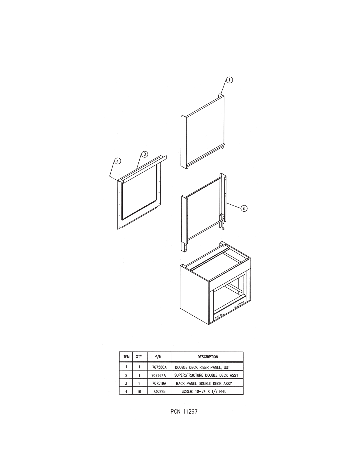
Double Deck Riser Kit Without Shelves P/N 788368A
– 50 –
Page 51

Double Deck Riser Kit With Shelves P/N 788368A
– 51 –
Page 52

NOTES
FORM 31203 Rev. A (March 2002) PRINTED IN U.S.A.
– 52 –
 Loading...