

Page 1
SERVICE MANUAL
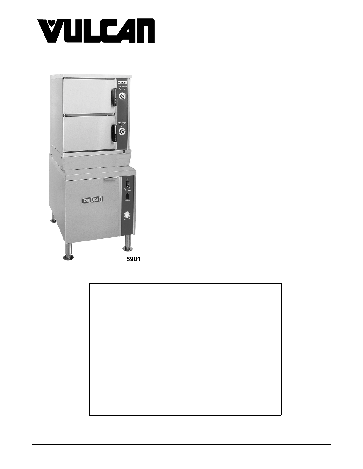
VHX BOILER BASE SERIES
HIGH EFFI CIENCY GAS
STEAMERS
VHX24G ML-114795
VHX24G5 ML-126590
MHB24G ML-114954 (BASE ONLY)
VHX24G SHOWN
This Manual is prepared for th e use of trained Vulcan Service
Technicians and should not be used by those not properly
qu alif ied. If yo u have attend ed a Vulcan Service School for this
product, you may be qualified to perform all the procedures
described in this man ual.
Thi s manu al i s no t i nten ded to be al l en comp assi ng . I f you have
not attende d a Vulcan S ervic e School for this produ ct , you should
read, in its entirety, the repair procedure you wish to perform to
determine if you have the necessary tools, instruments and skills
required to perform the procedure. Procedures for which you do
not have th e n ecessary too ls, in strument s and skills should be
performed b y a trained Vu lcan Service Technician .
Reproduction or other use of this Manual, without the express
written consent of Vulcan, is prohibited.
- NOTICE -
A product of VULCAN-HART LOUISVILLE , KY 40201-0696
F24700 (October 2001)
Page 2

VHX SERIES STEAMERS
TABLE OF CONTENTS
GENERAL............................................................................. 4
Installation......................................................................... 4
Maintenance ....................................................................... 4
Cleaning .......................................................................... 4
Introduction ........................................................................ 4
Steam Cooking.................................................................. 4
Compartment Pan Capacity ........................................................ 4
Model Designations .............................................................. 4
Boiler Code Descr iptions .......................................................... 4
Boiler Control Styles.............................................................. 5
Water Conditi oning .................................................................. 6
Specifications ...................................................................... 6
Water Supply ................................................................... 6
Electrical ...................................................................... 6
Boiler Pressure.................................................................. 6
Gas Supply ..................................................................... 7
Tools ............................................................................. 7
STEAMER OPERATION.................................................................. 8
Cabinet Base Boiler .................................................................. 8
Cooking Compartment Controls......................................................... 8
Boiler Blowdown and Steamer Shut off ................................................... 9
Component Func tion ................................................................ 10
Cabinet Base Boiler Controls ...................................................... 10
Cooking Compartment Controls .................................................... 12
REMOVAL AND REPLACEMENT OF PARTS ................................................ 13
Component Locat ions ............................................................... 13
Cabinet Base Boiler Controls ...................................................... 13
Cooking Compartment Controls .................................................... 15
Water Level Controls
(Main or Auxiliary LLCO) ......................................................... 15
Relay Board....................................................................... 15
Water Level Gauge Assembly ......................................................... 16
Pressure Switches .................................................................. 16
Boiler Assembly.................................................................... 16
Boiler Fill and Cold Water Condenser Solenoi d V alves ...................................... 17
Pilot Gas Valve .................................................................... 17
Main Gas Valve.................................................................... 17
Burner Head Assembly .............................................................. 18
Complete Burner Assembly ........................................................... 18
Heat Exchanger .................................................................... 19
Cooking Compartment Door(s)......................................................... 21
SERVICE PROCEDURES AND ADJUSTMENTS .............................................. 23
Boiler............................................................................ 23
Inspection..................................................................... 23
Clean-Out ..................................................................... 23
Deliming...................................................................... 23
Descaler (Cathodic Protector ) ...................................................... 24
Water Level Probe Housing Blowdown .................................................. 24
Water Level Controls Test ............................................................ 25
Pressure Switches .................................................................. 27
Fill and Cold W ater Solenoid V alves .................................................... 28
Boiler Blowdown/drain Solenoid Valve .................................................. 29
Inline Water S trainer Cleaning ......................................................... 29
Main Burner Ignition Checks .......................................................... 30
F24700 (October 2001) Page 2 of 68
Page 3

VHX SERIES STEAMERS
Air Pressure Switch Adjustment........................................................ 33
Gas Pilot Pressure Adjustment......................................................... 34
Gas Manifold Pressure Adjustment ..................................................... 36
Ignition Control Module Checks ........................................................ 37
Cooking Compartment............................................................... 39
Intake Shut-Off Valve Adjustment (Steam Flow)........................................ 39
Door Sealing Adjustment ......................................................... 39
Door Latch Adjustment........................................................... 40
ELECTRICAL OPERATION .............................................................. 41
Water Level Controls................................................................ 41
Low Level Cut-Off & Differential Control.............................................. 41
Auxiliary Low Level Cut-Off ....................................................... 42
Relay Board....................................................................... 43
Board Layout and LED Legend ..................................................... 43
Boiler Operational Status (LED Indicator) ............................................. 44
Sequence of O per ation .............................................................. 46
New Style Controls - Boiler........................................................ 46
Old Style Controls - Boiler ........................................................ 48
Cooking Compartment Controls .................................................... 50
Schematics ....................................................................... 52
Models Built After 5/25/00 (New Style Boiler Controls) ................................... 52
Models Built Befor e 5/25/00 (Old S tyle Boiler Controls) .................................. 54
Cooking Compartment Controls .................................................... 55
Wiring Diagrams ................................................................... 56
Models Built After 5/25/00 (New Style Boiler Controls) ................................... 56
Models Built Befor e 5/25/00 (Old S tyle Boiler Controls) .................................. 58
Cooking Compartment Controls .................................................... 60
TROUBLESHOOTING .................................................................. 61
CONDENSED SPARE PARTS LIST ........................................................ 68
© VULCAN 2001
F24700 (October 2001)Page 3 of 68
Page 4
VHX SERIES STEAMERS - GENERAL
GENERAL
INSTALLATION
Refer to the Installation and Operation Manual for
detailed installation instructions.
MAINTENANCE
Refer to the Installation and Operation Manual for
specific maintenance instruct ions.
CLEANING
Refer to the Installation and Operation Manual for
specific cleani ng instructions.
INTRODUCTION
Steam Cooking
Convection cooking in pressure-less steaming
compartments will steam cook fresh foods or will
steam def rost and cook froz en foods prov iding the
maximum c olor, flav or and nutritional value with the
least expenditure of energy and labor. T he pr essureless steaming compartm ents on the VHX series
allows the operator to open and close the door,
anytim e during a cooking cycle. T he steam supply
will shut off when the door is opened, then re-start
when the door is closed.
Compartment P an Capacity
PAN
DEPTH
(INCHES)
MODEL
VHX24G
NUMBER OF PANS
PER COMPARTMENT
24.0
32.5
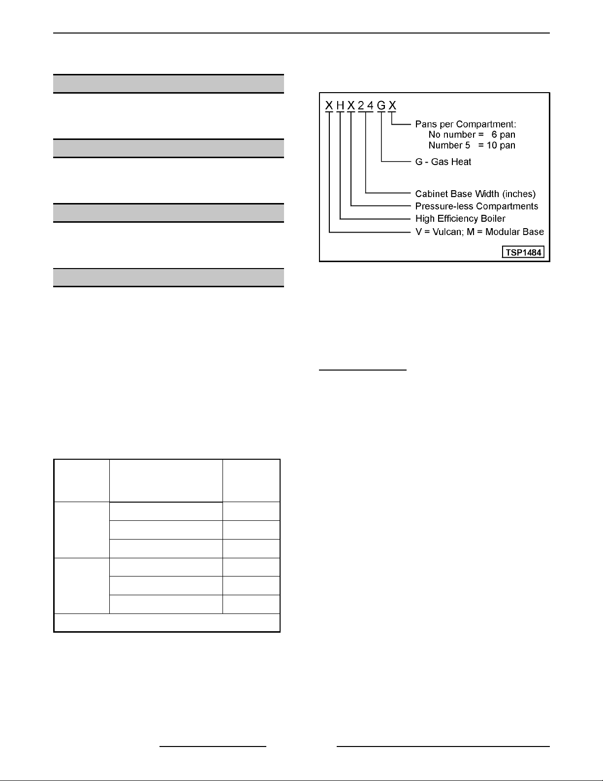
Model Desi gnations
Boiler Code Descriptio ns
Vulcan-Hart incorporates redundant c ontrols in
compliance with the CSD-1 controls and safet y
devices for boiler construction on these High
Efficienc y S team models. A Description of the c ode
is listed below.
CSD-1 Constructi on
electrical safety circuits that, i f tri pped, must
manually be reset after the condit ion causing the trip
subsides. These controls consist of - (1) dual
function water level cycling and low level cut off
control and ( 1) si ngle funct ion low water level cut-off
control ( A ux LLCO) and a high pr essure rel ief switch
in conjunction with a mechanical pr essure rel ief
valve. A dditional ly, both circuits have indi vidual
indicat or lights for low water and high pressure that
will illuminate for a visual verification of the
shutdown mode.
CSD-1 construction requires operator intervention i n
the ev ent of a shutdown. The i ndicator l ights show
the operator which safety system was shutdown.
- Redundant controls in the
61.0
34.0
VHX24G5
Pan Size 12" x 20"
F24700 (October 2001) Page 4 of 68
52.5
10 1.0
Page 5
VHX SERIES STEAMERS - GENERAL
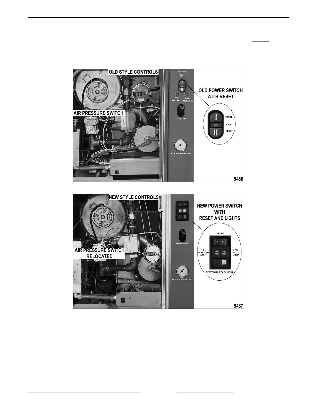
Boiler Control Styles
VHX Steamers manufactur ed usi ng the old style boiler controls ended on 5/19/00. Steamers that were in stock at
the time of the boiler contr ol changeov er were removed and equipped with the new style c ontrols without
recording t he serial number for track ing.
Refer to the pictures bel ow to differentiate between the old style and new style boiler controls.
F24700 (October 2001)Page 5 of 68
Page 6
VHX SERIES STEAMERS - GENERAL
WATER CONDITIONING
Furnishing the boiler wit h treated water to reduce
scale formation is import ant. Scale format ion will
reduce steam out put, cause prematur e c omponent
failure, and shorten equi pment life. Most water
supplies contai n scale producing m inerals such as
Calcium and Magnesium. As steam is generated,
the mi nerals remai n and dissolve into the water. As
the concentrat ion of these minerals i nc r eases past a
certain point, they pr ec ipitate from the water and
coat the inside of the boi ler, heating element s, and
water level sensors. Because of the high
temperat ure of these surf ac es, the precipitated
minerals bake onto them and bec ome v er y difficult
to remove.
This may c ause several probl ems:
1. Reduced heat transf er eff iciency.
2. Premature heating element failures.
3. False readings from water l evel sensors.
These problem s are common to any manufacturer's
steamer regardless of design, but t hey c an all be
minimized by furnishing the boiler with treated
water.
Other factors affecting steam generati on ar e iron
content, amount of c hlorination and dissolved
gases.
SPECIFICATIONS
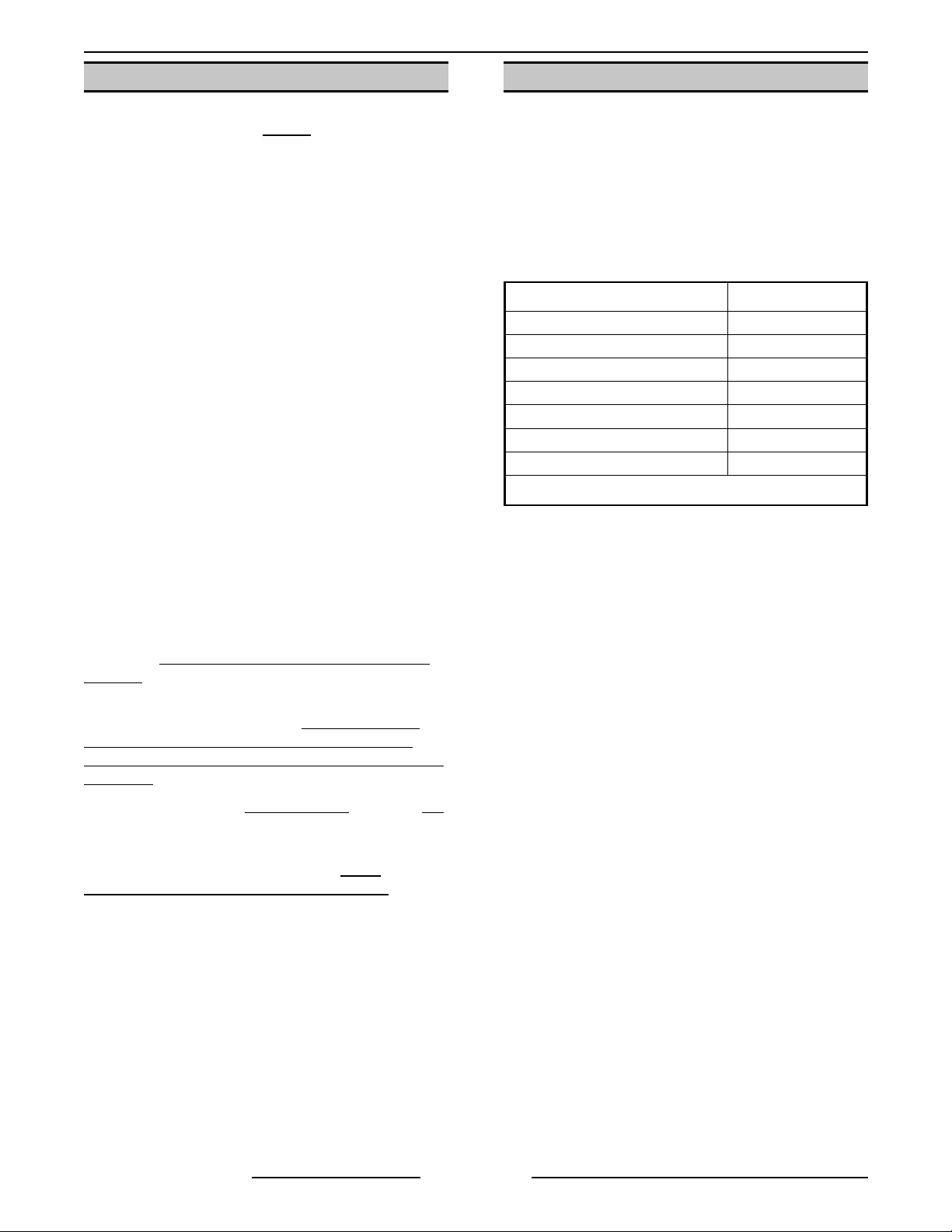
Water Supply
The fact that a water supply is potable is no
guarantee that it is suitable for steam generation.
The supply connect ion to the steam gener ator
should be “treated” water and must be within t he
guideli nes listed below. For dr ain water cooling only,
an “untreated“ water suppl y c onnec tion should be
used.
Supply pressure should be 20-60 psig
In line strainer f or suppl y line (Not Supplied)
Supply connection cold
Total dissolved solids (TDS)* less than 60 ppm
Total alkalinity less than 20 ppm
Silica less than 13 ppm
Chloride less than 30 ppm
PH fact or 7 to 8
(*17.1 ppm = 1 grain of har dness)
Electrical
Voltage - 120/ 60/1
Amps - 3.0 (max)
The desired water propert ies can best be achieved
by using a
system.
The water level probes in the boiler use ions i n the
water to detect the water level.
demineralized or de-ionized water since it is
"non conductive" and the water level can not be
detected.
The use of strainers or
remove mi nerals from the water.
Water supplies vary fr om state to state and from
locati ons wit hin a state. Therefore, a
treatment specialist should be consulted
the installation of any steam generating equipment.
Steamers that operate over a long peri od of time
without the benefit of a water treatment system,
which have developed a heavy scale build up,
should be cleaned before using the system.
properly maintained water treatment
Do not use fully
non approved
filters will not
water
before
Boiler Pressu re
Operating - 8 to 10 psi
Maximum - 15 psi
F24700 (October 2001) Page 6 of 68
Page 7
Gas Supply
VHX SERIES STEAMERS - GENERAL
MODEL
VHX24G
VHX24G5
MHB24G
NOTE
Standard
INPUT
(BTU/HR)
NAT. PROP. NAT. PROP. NAT. PROP.
200,000 200,000 3.0 3.0 3.5 3.5 7.0 11.0
270,000 270,000 3.0 3.0 3.5 3.5 7.0 11.0
200,000 200,000 3.0 3.0 3.5 3.5 7.0 11.0
270,000 270,000 3.0 3.0 3.5 3.5 7.0 11.0
200,000 200,000 3.0 3.0 3.5 3.5 7.0 11.0
270,000 270,000 3.0 3.0 3.5 3.5 7.0 11.0
1. Output Boiler Horsepower (BHP): 4.3 BHP for 200,000 BTU; 5.5 BHP for 270,000 BTU.
:
2. Input BTU/HR difference is based on gas orifice size and air orifi c e size.
MANIFOLD
PRESSURE
(INCHES W.C. )
PILOT
PRESSURE
(INCHES W.C. )
NATURAL PROPANE
MINIMUM
RECOMMENDED
LINE PRESSURE
(INCHES W.C. )
RECOMMENDED
TOOLS
MINIMUM
MAXIMUM
ALLOWED
14.0
Standard set of hand tools.
Volt-Ohm-Meter (VOM) with AC current tester.
(Any quality VOM wit h a sensit ivity of at least 20,000 ohm s per volt c an be used)
Gas leak checking equipment.
Gas pressure manomet er
Temperat ure meter and t her mocouple.
Special
The recommended deli ming chemical for the water treatment system in use, for deliming of the boiler.
Contact Vul c an A uthorized Service Centers.
Heat Exchanger Gasket (joi nt sealant strip, Teflon) P /N 854058-1.
F24700 (October 2001)Page 7 of 68
Page 8

VHX SERIES STEAMERS - OPERATION
STEAMER OPERATION
CABINET BASE BOILER
Ensure that all utility connections to the steamer
have been made and are turned ON and t hat the
knob on the main gas valve is i n the ON positi on.
The VHX Series steam er s are CSD- 1 c ompliant and
are equipped with amber colored lights on the boiler
control panel for Hi gh P ressure and Low Water level
that illuminate and stay on until the boiler is full and
the manual reset switch pressed.
1. Turn power switch ON.
A. Amber colored lights on the boiler control
panel for High Pressure and Low Water
level will illuminate. and stay on until t he
boiler is full and the reset switch is
pressed.
B. Water will begin filling the boiler and the
blowdown solenoid v alve will close. The
boiler shoul d fill, in four to eleven minutes.
C. As water fills the boiler, observe water
level gauge glass to verify that water i s i n
boiler. See "WATER LEVEL GAUGE
ASSEMBLY" in "COMPONENT
FUNCTION” and COMPONENT
LOCATION “ under "REMOVAL AND
REPLACEMENT OF PARTS".
D. Onc e the water in the boiler reaches the
minimum level, the green ready light on
the boiler control panel will illuminate.
NOTE: If the fill has stopped, one visible inc h
of water should be in the gauge glass.
2. Press the reset switch on the boiler control
panel.
A. Low water level safety circuit will be reset
and the Low Wat er lev el light (amber) will
turn off.
B. High pressure safety circuit will be reset
and the High Pressure light (amber ) will
turn off.
C. Sparking will begin three seconds later to
light the pilot bur ner.
1) I f the pilot burner lights, a signal is
sent back through the igniti on c able
indicat ing the presence of pilot burner
flame and sparking stops.
2) I f pil ot burner flame is not
established immedi ately, sparki ng will
continue for 90 seconds. After that
duration, the ignition control module
will lock out and needs to be reset to
start the pilot and main burner li ghting
cycle again.
New Style Controls
Pilot gas valve operates on a "timer"
circuit allowing gas flow to the pilot
for approximately 15 seconds, during
ignition trial, then turns off.
D. Main gas valve opens, burner ignites and
begins to heat the water in the boil er . After
approximately 15 minutes, steam should
be present for c ook ing product. O bserve
that the boi ler pressure gauge indicates a
steam pressure of 8- 10 psi before the
burner shuts OFF.
3. The cycling pressure switch will maintain steam
pressure in the boiler by cycling the main
burner ON and OF F.
- Power to the
COOKING COMPARTMENT
CONTROLS
When the steam pressure in the c ook ing
compartment manifol d reaches approximately 3 psi,
the cooking compartment pressure switch closes,
suppling power to the ot her c ook ing compart ment
controls. The ready lights will illuminate and after
approximately one minute, the steam pressure in
the boiler will reach the upper limit of 10 psi. If the
pressure drops below approximately 3 psi, the
pressure switch will open, removing power fr om the
controls.
NOTE:
immediatel y after t he ready light c omes on, steam
solenoid chattering will be heard (oil canning) and
the ready lights will flash for several seconds. This
conditi on is caused by the mani fold steam pressure
being on the “fringe” of the pressure switch set point.
When a c ook timer is set, the compar tment steam
solenoid valve opens causing the manifold st eam
pressure to drop, slightly below the pressure switch
set point. At the same time, steam pressure is still
increasing in the boiler . This opposing condition
causes a pressure “bounce” to occur. After the
steam pressure passes approxim ately 4 psi this
conditi on subsides. Dur ing normal oper ation, this
conditi on will not be seen.
On initial startup, if a cooking ti mer is set
F24700 (October 2001) Page 8 of 68
Page 9

VHX SERIES STEAMERS - OPERATION
1. With both timer knobs at the off posi tion, open
the compartment doors and observe that no
steam has entered the c ook ing compart ments,
then close the doors.
2. Set both timer knobs at 2 minutes. The r eady
lights will go off, the cooking lights will come
on, and steam will begin to enter the
compartments.
3. After one minute, open eac h door and observe
that steam has ceased to enter each
compartment, cooking lights go back to ready,
and one minut e is remaining on each cook
timer.
4. Close doors and steam generation and cook
timing will resume. Observe the floor drain to
ensure that live steam from compart ments is
being cooled by cold water fr om the cold water
condenser solenoid valve.
5. When timer k nobs reac h " 0" , buzzers will
sound, steam generation will cease, cooking
lights will go off and ready lights will come on.
To silence buz z er s, turn timer knobs to off
position.
BOILER BLOWDOWN AND
STEAMER SHUT OF F
Turn the steamer off at least once daily to bl owdown
the boiler. This will aid in the removal of sediment
and scale buil d- up in the boil er .
NOTE
: Boil er should be with-in normal operating
pressures.
1. Turn power switch OFF .
2. Boiler blowdown sequence starts.
A. The blowdown/drain solenoid valve will be
de-energized and t he boiler will begin to
drain.
B. The cold water condenser solenoid will
operate, as needed, to condense steam
and to cool the water going into the dr ain.
6. During idle t ime or a cooking cycle, the heating
system will cycle on and off as necessary to
maint ain steam pressure in t he boiler.
7. Turn power switch off to remove power from
the steamer.
A. Boiler blowdown starts.
F24700 (October 2001)Page 9 of 68
Page 10

VHX SERIES STE A M E RS - COMPONENT FUNCTION
COMPONENT FUNCTION
CABINET BASE BOILER CONTROLS
Power Switch (ON/OFF)
Reset Switch (Manual)
Boiler Fill Solenoid Valve
Cold Water Condenser
Solenoid Valve
Blowdown/Drain
Solenoid Valve
Cycling P ressure Switch
High Limit Pressure Sw itch
................. Allows cold water flow into the boiler blowdown drain box to condense
................. A normally open valve (N.O.) that closes to allow boiler to fill and
......... When turned ON, supplies power to the control cir c uit.
.......... Resets the low water level safety circuit on initial startup or the
......... Controls boiler pressure between prescribed limits by turning the heat
occurrence of a low water condition and allows the boil er to fill with
water. Also, resets the high pressure lev el safety circuit on initial startup
or the occurrenc e of a high pressure condition and all ows the gas
ignition cycle to start.
........ Admits water to the boiler when dem anded by the water level control to
maintain the correct water level in the boiler.
steam and cool the hot water befor e its discharge int o the drain.
pressurize when power switch is turned ON and opens when power
switch is turned off to blowdown and drain the boiler. This valve is
plumbed into the drain line of the boiler.
source on and off.
...... Protects the boiler from pressures above 15 psi by removing power from
the heating ci rcuit. Thi s pressure setting is higher than the cycling
pressure switch in order to t ur n off the heat source before the boiler
pressure reaches its limit. A fter the pr essure drops below approximat ely
12psi, press the rest switch of the front control panel to rest the safety
circuit.
Main Water Level Control
Auxiliary Water Level Control
Transformer
Ignition Control Module
Main Gas Valve
Pilot Gas Valve
................... Provides 24VAC power to ignition control modul e and heating circ uit.
................ A gas solenoid valve that opens to allow gas flow to the main burner
................ A gas solenoid valve that opens to allow gas flow to the pilot to ignite the
........ A dual functioning control that allows water to fill and maintain the
......... Controls and m onitors gas heating. E ner gizes pilot valve coi l to supply
proper level in the boiler pr oviding dif ferenti al water level control; and
shuts off the main gas valve if the water level drops too low providing
low level cut-off protection. The water level control works by using three
different probe lengths to moni tor the water level. The probes consist of
a high level (HL) , low level (LL) and low water cut- off ( LLCO).
..... A back up to the low level cut-off on the main control. Protects the boiler
and heating system c omponents from a low water cut-off condition by
opening the 24VAC volt age path to the heati ng system circuit. Al so,
energizes the l ow water "l ight" on the front contr ol panel.
gas to pilot, generates spark to ignite gas at the pilot, monitors the
presence of flame and energizes the main and pilot valve coi ls on the
main gas valve upon a call for heat.
after the successful ignition of the pil ot burner when a call for heat is
made.
main burner when a call f or heat is made. T he valve is energized by a
tim e delay circ uit on the rel ay boar d dur ing ignit ion trial for
approximately 15 seconds. New styl e c ontrols only.
Combustion Blower
F24700 (October 2001) Page 10 of 68
............ Provides forced air to the gas/air mixture for gas pilot and m ain burner
combustion.
Page 11

VHX SERIES STE A M E RS - COMPONENT FUNCTION
Relay Board
................... Provides a centralized location for wire harness connections and power
transfer through board relays (K1-K 7) to the steamer controls. Also,
provides a condition or component t r oubleshooting indicator by utilizing
seventeen LED’S on the board to represent the status of the condi tion or
component in the operation sequence. For an LED legend, see "RELA Y
BOARD" under "E LE CTRICAL OPERATION". New style c ontrols only.
: The relay’s below are mounted on the relay board and are not
NOTE
K1 Relay
...................... Energized when Aux LLCO is satisfied and turns ready light ( gr een) ON
if high limit pressure switch i s closed. Also, K1 allows K3 to be energized
when the reset switch is pressed.
K2 Relay
...................... Energized when high li mit pressure switch is closed (high limit pressure
conditi on sat isfied). When K 1 & K 2 ar e ener gized, the ready light (green)
will be ON.
K3 Relay
...................... When Aux LLCO is satisfied and the m anual reset switch is activat ed,
K3 is energized. When K 3 is energized, tur ns water error light OFF and
allows the ignition sequence to begi n. K3 must be energi z ed for ignition
sequence to begin.
K4 Relay
...................... Energized when K2 contacts are closed and manual reset switch is
activated. When K4 i s energized, the high pressure light is OFF. When
K3 and K4 are both energized, power to the ignition system is supplied.
K5 Relay
...................... Energized when operating conditions are m et and reset switch is
activated. Pr ovides power to start combustion blower.
individual ly replaceable.
K6 Relay
...................... Energized by time delay circuit for approx imately 15 seconds. When K 6
and K7 are energized, power is supplied to the pilot gas valve.
K7 Relay
...................... Energized when pilot voltage (PV) f r om the ignition module is present.
Also used in the time delay c ircuit.
......................... Ignites to light the main burner upon a call f or heat.
Pilot
Main Burner
................... Heats the water in the boiler to gener ate steam.
Water Level
Gauge Assembly
............... Permits a visual confirmation the water level is being maintained in
boiler dur ing operation. The correct water l evel is approximately one
visible inch in the glass. The manual valves at the top and bott om of this
assembly m ust be full y open and only closed if the glass tube is
damaged.
Water Inlet Valve (manual)
....... The water inlet valve is used to stop water flow to the steamer when the
steamer i s bei ng serviced. This valve should remai n open dur ing normal
operation.
Inline Water Strainer
............ A "Y" strainer is installed upstream of the blowdown solenoid valve to
prevent forei gn matter from becoming lodged in the valve. A strainer
(not supplied) shoul d also be installed in the water supply line to prevent
forei gn matter from becoming l odged in the fill or cold water condenser
solenoid valves and to keep unwanted partic les out of the system.
Pressure Relief V alve
........... A mechani c al device that opens to relieve steam pressure in the boiler if
the pressure exceeds 13 psi.
High Pressu re Relief Valve
Descaler
Boiler Pressu re Gauge
...................... Hangs below the water level inside the boi ler and is used to help cont r ol
.......... Indicates the amount of steam pressure in the boi ler.
Steam Header Assembly
....... A back-up mechanical device that opens to relieve steam pressure in
the boiler if the pressure exceeds 15 psi.
boiler surface scaling. Two descalers are used in each boiler.
......... Main steam supply line fr om the boiler to the steam header inlet in the
cooking control compar tment.
F24700 (October 2001)Page 11 of 68
Page 12

VHX SERIES STE A M E RS - COMPONENT FUNCTION
COOKING COMPARTMENT CONTROLS
The upper section of the steam er c onsi sts of two separate cooking compartm ents. Each compartment functions
independently wi th its own set of contr ols. Power is supplied to the controls only after the steam pressure rises
above t he c ompartm ent pressure switch setting to close the N.O. contacts.
Ready Light (Green)
Cooking Light (Red)
Cooking Timer
Buzzer
Door Switch
Steam Solenoid Valve
Compartment P r essure Switch
Manifold Pressure Gau ge
Steam Supply Manifold
....................... Signals end of a cook cycle, must be turned off manual ly.
................... Removes electrical power to the timer. If time is dialed on the cooking
............ When lit, indicates steamer is ready to cook.
............ When lit, indicates steamer is in a cooking cycle.
................. Use to set desired cooking cycle time between 0-60 minutes. When a
........... When energi zed, opens to allow steam into the cooking compartment
........ Indicates the amount of steam pressure in manifold. The intak e shut- off
.......... Main steam supply line fr om the boiler for eac h c ook ing compart ment.
tim er is set, the steam suppl y sol enoid valve is energized to al low steam
into the cook ing compartment but only after the boiler has reached its
operating pressure. Also, energizes the buzzer when time expires.
tim er and compartments are steaming, removes power to the steam
solenoid valve when the compart ment door is opened.
(normally closed valve).
.... Supplies power to the controls only after the steam pressure ri ses above
approximately 3 psi to close the compartment pressure switch. The
switch remains closed as long as steam pressure stays above this
pressure.
valve should be adjusted so manifold pressure remains at 9 psi with both
compartments on.
Supplies steam up to the steam sol enoid valve.
Intake Shut-Off Valve
........... Main steam supply shut-off from the boiler t o the steam supply manif old.
This valve should NOT be left fully O P E N to boiler steam supply. See
“INTAKE SHUT-OFF VALVE ADJUSTMENT (STEAM FLOW)" in
“SERVICE PROCEDURES AND ADJUSTMENTS".
F24700 (October 2001) Page 12 of 68
Page 13
VHX SERIES STEAMERS - REMOVAL AND REPLACEMENT OF PARTS
REMOVAL AND REPLACEMENT OF PARTS
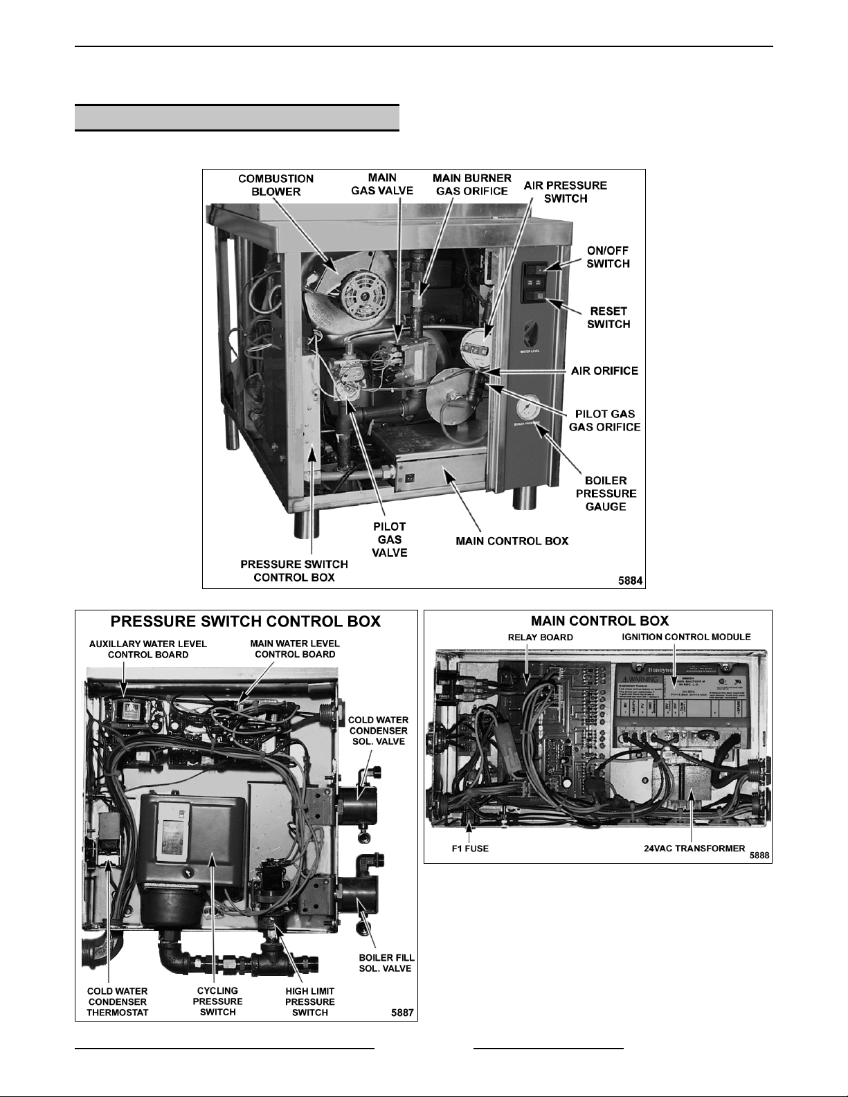
COMPONENT LOCATIONS
Cabinet Base Bo iler Contro ls
F24700 (October 2001)Page 13 of 68
Page 14
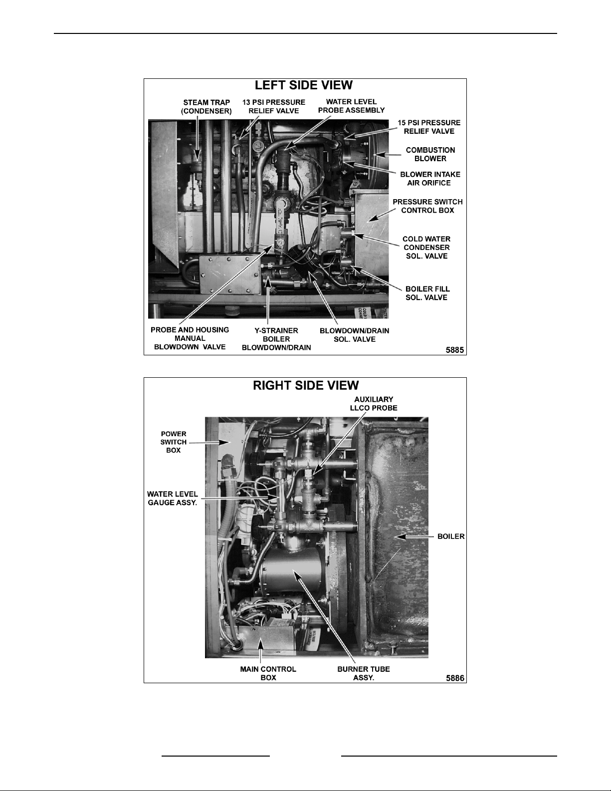
VHX SERIES STEAMERS - REMOVAL AND REPLACEMENT OF PARTS
Cabinet Base Bo iler Contro ls Contin ued
F24700 (October 2001) Page 14 of 68
Page 15
VHX SERIES STEAMERS - REMOVAL AND REPLACEMENT OF PARTS
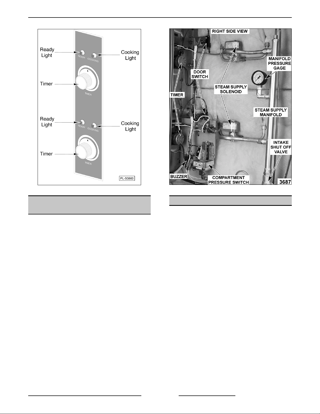
Cooking Compartment Controls
WATER LEVEL CONTROLS
(MAIN OR AUXILIARY LLCO)
WARNING:
POWER TO T HE MACHINE AT THE MAIN
CIRCUIT BO X. P LA CE A TAG ON THE CI RCUIT
BOX INDICATING THE CIRCUIT IS BEING
SERVICED.
1. Open the cabinet base door.
2. Remove the cover from the pressure switch
control box to access the water level controls.
Refer to "CABINET BASE BOILER
CONTROLS" under "COMPONENT
LOCATIONS" in "REMOVAL AND
REPLACEMENT OF PARTS".
3. Disconnect l ead wir es from the boar d being
replaced.
4. Compress the lock ing tab on the board
mounti ng "standoffs" and remove the water
level control.
5. Reverse proc edur e to install and c hec k for
proper operati on.
DISCONNECT THE ELECTRICAL
RELAY BOARD
WARNING:
POWER TO T HE MACHINE AT THE MAIN
CIRCUIT BO X. P LA CE A TAG ON THE CI RCUIT
BOX INDICATING THE CIRCUIT IS BEING
SERVICED.
1. Open the cabinet base door.
2. Remove the cover from the main control box to
access the relay board. Refer to "CAB INET
BASE BOILER CONTROLS" under
"COMPONENT LOCATIONS" in "REMOVAL
AND REPLACEMENT OF PARTS".
3. Disconnect all lead wires f r om the board.
4. Compress the lock ing tab on the board
mounti ng "standoffs" and remove the relay
board.
5. Reverse proc edur e to install and c hec k for
proper operati on.
DISCONNECT THE ELECTRICAL
F24700 (October 2001)Page 15 of 68
Page 16

VHX SERIES STEAMERS - REMOVAL AND REPLACEMENT OF PARTS
WATER LEVEL GAUGE
ASSEMBLY
WARNING:
POWER TO T HE MACHINE AT THE MAIN
CIRCUIT BO X. P LA CE A TAG ON THE CI RCUIT
BOX INDICATING THE CIRCUIT IS BEING
SERVICED.
1. Open the cabinet base door and remove the
right side panel.
2. Close the valve at the top and at the bottom of
the gauge assembly.
3. Unscrew the packing nuts at t he top and bottom
of the glass tube.
4. Slide t he glass tube upwards until the bottom of
the tube is clear of the fitt ing and lift it out.
NOTE
damaged or broken.
NOTE:
gauge glass may break.
5. Install the tube using new sealing washers.
6. Open the top and bottom valves.
7. Turn the power switch ON and allow boiler t o
come up to pressure.
8. Check gauge glass for water/steam leaks and i f
necessary, graduall y tighten packing nuts until
leak stops.
DISCONNECT THE ELECTRICAL
: Clean tube if dir ty or clogged and replace if
Do not ov er tighten the pack ing nuts or
PRESSURE SWITCHES
WARNING:
POWER TO T HE MACHINE AT THE MAIN
CIRCUIT BO X. P LA CE A TAG ON THE CI RCUIT
BOX INDICATING THE CIRCUIT IS BEING
SERVICED.
1. Open the cabinet base door and remove the
left side panel.
2. Remove the cover from the pressure switch
control box to access the pressure switches.
Refer to "CABINET BASE BOILER
CONTROLS" under "COMPONENT
LOCATIONS" in "REMOVAL AND
REPLACEMENT OF PARTS".
3. The pressure switches are located at the
bottom of the box . The pressure switch on the
left is the cycling
the right is the high limit
4. If replacing:
A. Cycling control - remove cov er from
DISCONNECT THE ELECTRICAL
or primary control ; the one on
control.
pressure switch and disconnect the lead
wires.
1) Remove the mounti ng screws on the
back side of the control box and lift
out the pressure switch. Proc eed to
step 5.
B. High li mit control - disconnec t the lead
wires.
5. Disconnect the pressure fittings at the bottom
of the switc h.
6. Preset the new pressure switch to the
approximate cut-out (OFF) and cut-in (O N) set
points befor e installing. Refer to "PRESSURE
SW ITCHES" in " S E RV ICE PROCEDURES
AND ADJUSTMENTS".
7. Reverse proc edur e to install .
8. Adjust the pressure switch(s) final set points as
outlined under "P RESSURE SWITCHES" in
"SERVICE PROCEDURES AND
ADJUSTMENTS".
BOILER ASSEMBLY
WARNING:
POWER TO T HE MACHINE AT THE MAIN
CIRCUIT BO X. P LA CE A TAG ON THE CI RCUIT
BOX INDICATING THE CIRCUIT IS BEING
SERVICED.
WARNING:
SERVICING THE UNIT.
WARNING:
DURING SERVI CING MUST BE CHECK E D FOR
LEAKS. CHECK WITH A SOAP AND WATER
SOLUTION (BUBBLES). DO NOT USE AN OPEN
FLAME.
1. Blowdown the boiler and, if nec essary, allow to
cool.
2. Disconnect the steam supply line, power leads
and drain lines from the cooking compartment
top to the boi ler base.
3. Refer to " HE A T EXCHANGER" and perform
steps 3 through 12A.
4. Remove bolts securing the boiler t o frame.
5. Drain any remaining water from t he boiler.
A. The suggested methods are:
DISCONNECT THE ELECTRICAL
SHUT OFF THE GAS BEFORE
ALL GAS JOINTS DISTURBED
1) Where the dr ain line exits the boiler
on the lower left side, separate the
drain line union.
2) Remove the access panel between
the boiler and the cooking
compartment on the right side.
3) Disconnect the steam supply hose
from the cooking compartment steam
manifold.
F24700 (October 2001) Page 16 of 68
Page 17

VHX SERIES STEAMERS - REMOVAL AND REPLACEMENT OF PARTS
a. From t he bottom right side, raise
the boiler two to three inches so
it tilts to the left. When the
remaining water has drained out,
lower the boiler before.
proceeding.
B. Remove the drain/ scale clean-out plug
from the bottom of the boiler.
6. Slide t he boiler forward and remove it from
base frame.
7. Install a new boi ler and secure it t o frame.
8. Refer to " HE A T EXCHANGER" and perform
steps 13 through 15.
9. Reconnect all steam, water, dr ain and power
connections and check for proper operat ion.
BOILER FILL AND COLD WATER
CONDENSER SOLENOID VALVES
WARNING:
POWER TO T HE MACHINE AT THE MAIN
CIRCUIT BO X. P LA CE A TAG ON THE CI RCUIT
BOX INDICATING THE CIRCUIT IS BEING
SERVICED.
1. Turn off the water supply to the steamer.
2. Open the cabinet base door and remove the
cover from the pressure switch control box to
access the solenoid valves. Both solenoi d
valves are l oc ated side by side at the r ear of
the box with the boiler fill near the bottom and
the cold water condenser near the middle.
Refer to "CABINET BASE BOILER
CONTROLS" under "COMPONENT
LOCATIONS" in “REMOVAL AND
REPLACEMENT OF PARTS”.
3. Disconnect the power l ead wir es from the
solenoid valve being serviced.
4. Disconnect the water lines for the valve bei ng
servi ced and remove the valve.
5. Reverse proc edur e to install .
DISCONNECT THE ELECTRICAL
PILOT G AS VALVE
WARNING:
POWER TO T HE MACHINE AT THE MAIN
CIRCUIT BO X. P LA CE A TAG ON THE CI RCUIT
BOX INDICATING THE CIRCUIT IS BEING
SERVICED.
WARNING:
SERVICING THE UNIT.
DISCONNECT THE ELECTRICAL
SHUT OFF THE GAS BEFORE
WARNING:
DURING SERVI CING MUST BE CHECK E D FOR
LEAKS. CHECK WITH A SOAP AND WATER
SOLUTION (BUBBLES). DO NOT USE AN OPEN
FLAME.
NOTE:
servi ceable and should not be di sassembl ed. Once
the problem has been isolated to t his component,
replace it. Do not attempt to repair the assembly.
1. Open the cabinet door to access the Pilot gas
valve.
2. Disconnect the lead wires.
3. Remove pilot gas tubing from the top of the
valve (outlet side).
4. Remove the valve from the gas supply piping.
5. Reverse proc edur e to install and adjust pilot
pressure as outlined under "G A S P ILOT
PRESSURE ADJUSTMENT" in "SERVICE
PROCEDURES AND ADJUSTMENTS".
ALL GAS JOINTS DISTURBED
Gas combination control valves are not
MAIN GAS VALVE
WARNING:
POWER TO T HE MACHINE AT THE MAIN
CIRCUIT BO X. P LA CE A TAG ON THE CI RCUIT
BOX INDICATING THE CIRCUIT IS BEING
SERVICED.
WARNING:
BEFORE SERVICING THE UNIT.
WARNING:
DURING SERVI CING MUST BE CHECK E D FOR
LEAKS. CHECK WITH A SOAP AND WATER
SOLUTION (BUBBLES). DO NOT USE AN OPEN
FLAME.
NOTE:
servi ceable and should not be di sassembl ed. Once
the problem has been isolated to t his component,
replace it. Do not attempt to repair the assembly.
1. Open the cabinet base door to access the mai n
gas valve.
2. Disconnect the lead wires.
3. Separate the uni on above the gas valve (outlet
side).
4. Remove the valve from the gas supply piping.
5. Reverse proc edur e to install and adjust
manifold pressure as outlined under "GAS
MANIFOLD PRESSURE ADJUSTMENT" in
"SERVICE PROCEDURES AND
ADJUSTMENTS".
DISCONNECT THE ELECTRICAL
SHUT OFF THE GAS SUPPLY
ALL GAS JOINTS DISTURBED
Gas combination control valves are not
F24700 (October 2001)Page 17 of 68
Page 18
VHX SERIES STEAMERS - REMOVAL AND REPLACEMENT OF PARTS
BURNER HEAD ASSEMBLY
WARNING:
POWER TO T HE MACHINE AT THE MAIN
CIRCUIT BO X. P LA CE A TAG ON THE CI RCUIT
BOX INDICATING THE CIRCUIT IS BEING
SERVICED.
WARNING:
BEFORE SERVICING THE UNIT.
1. Remove the pressure gauge tubing and power
cable f r om the rear of the control panel then
remove the panel.
2. Disconnect the spark igniti on c able from the
ignitor termi nal.
3. Disconnect pilot gas tubing from the air
pressure switch tee.
4. Separate the uni on above the main gas v alve
and remove the gas v alve piping assembly .
NOTE
assumes the use of a gas line quick connect or
union at the gas supply inlet to the steamer.
5. Remove the screws from the burner head
assembly end plate and pull the assembly out
from the complete burner assembly .
DISCONNECT THE ELECTRICAL
SHUT OFF THE GAS SUPPLY
: Removal of the gas valve piping assembly
3. Remove the four nuts from the burner tube
assembly then slowly
out from the heat exchanger.
pull the assem bly straight
6. Reverse proc edur e to install and c hec k for
proper operati on.
COMPLETE BURNER
ASSEMBLY
WARNING:
POWER TO T HE MACHINE AT THE MAIN
CIRCUIT BO X. P LA CE A TAG ON THE CI RCUIT
BOX INDICATING THE CIRCUIT IS BEING
SERVICED.
WARNING:
BEFORE SERVICING THE UNIT.
1. Refer to steps 1 thr ough 4 under "BURNER
HEAD ASSEMBLY".
2. Remove the four nuts from c ombustion bl ower
mounti ng flange and remove blower from
burner tube assembly .
DISCONNECT THE ELECTRICAL
SHUT OFF THE GAS SUPPLY
CAUTION: Use care w hile removing as to no t
damage the ceramic insulation surrounding the
burner.
4. Reverse proc edur e to install and c hec k for
proper operati on.
F24700 (October 2001) Page 18 of 68
Page 19
VHX SERIES STEAMERS - REMOVAL AND REPLACEMENT OF PARTS
HEAT EXCHANGER
WARNING:
SERVICING THE UNIT.
WARNING:
DURING SERVI CING MUST BE CHECK E D FOR
LEAKS. CHECK WITH A SOAP AND WATER
SOLUTION (BUBBLES). DO NOT USE AN OPEN
FLAME.
1. Blowdown the boiler and, if nec essary, allow to
cool.
2. Disconnect the electric al power to the machine
at the main circuit box. Place a tag on the
circuit box indicating the circui t is being
serviced.
3. Remove the pressure gauge tubing and power
cable f r om the rear of the control panel then
remove the panel.
4. Disconnect the electric al lead wires exiting the
boiler control box from:
SHUT OFF THE GAS BEFORE
ALL GAS JOINTS DISTURBED
NOTE
: Removal of the gas valve piping assembly
assumes the use of a gas line quick connect or
union at the gas supply inlet to the steamer.
8. Remove the four nuts from c ombustion bl ower
mounti ng flange and remove blower from
burner tube assembly .
A. Auxiliary LLCO probe (Orange).
B. Burner ground (green).
C. Air pressure switch (yellow & yellow/white
stripe).
D. Main gas valve (purple & grey).
E. Pilot burner valve (red & grey).
F. Spar k ignition cable.
5. Remove bolts securing the boiler control box
(front ) to the base frame.
A. Lift up on left side of box and slide out.
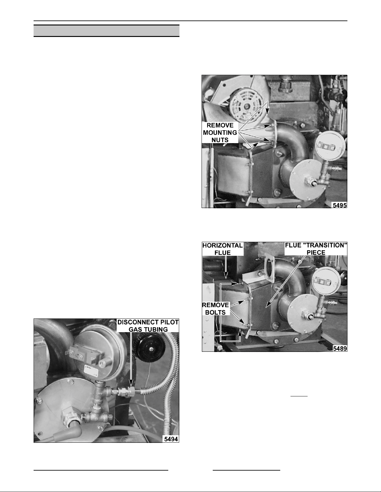
6. Disconnect pilot gas tubing from the air
pressure switch tee.
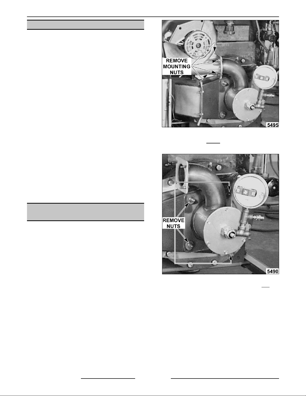
9. Remove the four bolts connecting the
horizontal flue (left of boil er) to the flue
"transition" piece.
A. Separate the horizontal flue f rom flue
"transition" piece, leaving the horizontal
flue in place.
7. Separate the uni on above the main gas v alve
and remove the gas v alve piping assembly .
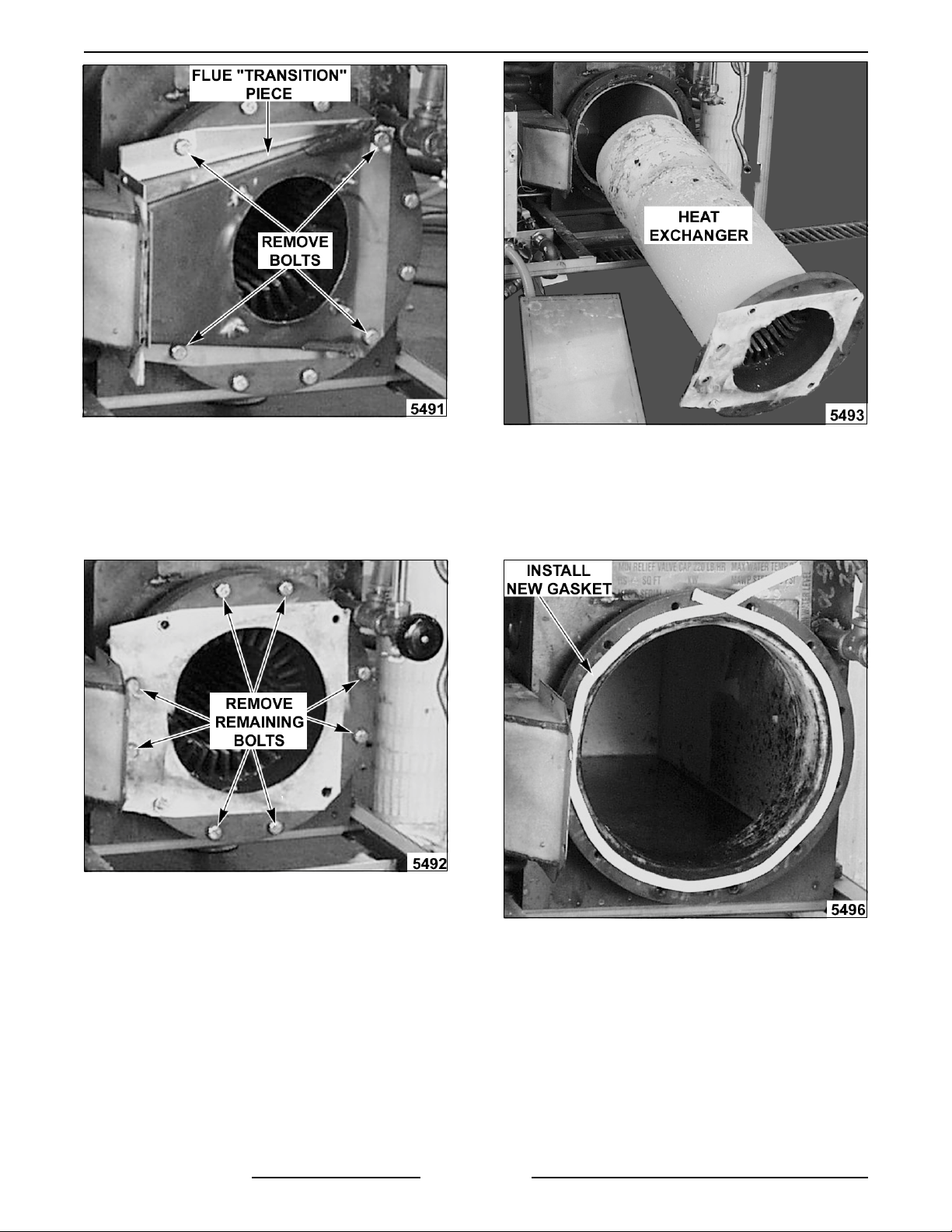
10. Rem ove the four nuts fr om the com plete
burner tube assembly then slowly
assembly strai ght out from the heat exchanger.
CAUTION: Use care w hile removing as to no t
damage the ceramic insulation surrounding the
burner.
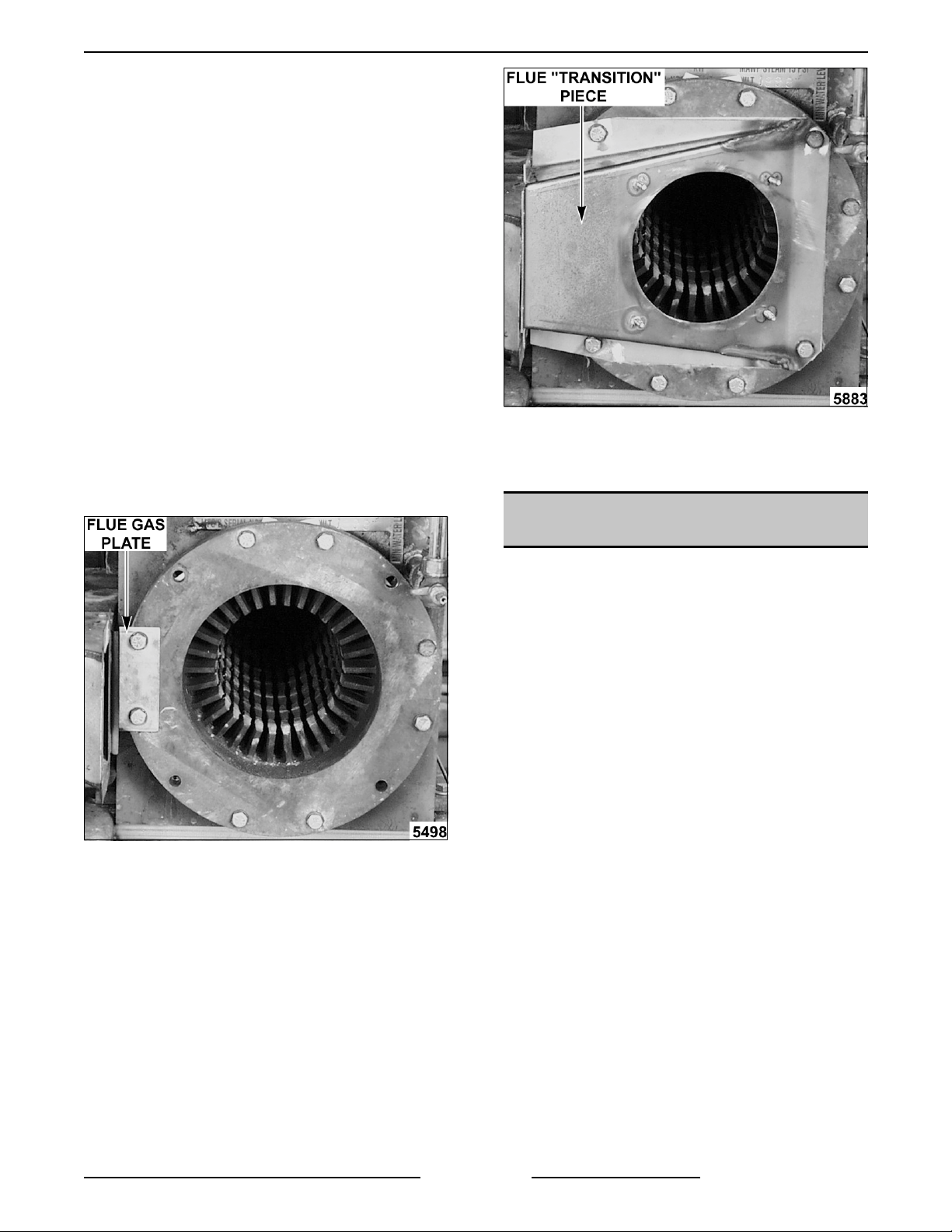
11. Rem ove the flue "tr ansi tion" piec e from the
heat exchanger.
F24700 (October 2001)Page 19 of 68
pull the
Page 20
VHX SERIES STEAMERS - REMOVAL AND REPLACEMENT OF PARTS
12. For c learance of the heat exchanger only,
remove the drain nut (petcock) and the lower
adjustment knob from the water level gauge.
A. Remove the remaining bolt s on the heat
exchanger then pull heat exchanger
straight out from the boiler.
13. To install heat exchanger:
A. Clean the m ating surfaces on the heat
exchanger and boi ler.
B. Install a new gasket on t he boiler side of
the mounting fl ange.
F24700 (October 2001) Page 20 of 68
C. Insert the heat exchanger bac k into the
boiler and line up the mounting holes
being careful not to disturb gasket.
D. At tach a 2" C-Clamp between the heat
exchanger mounting flange and the boiler
side mounting flange. Tighten clamp only
enough to allow start ing of bottom bolt into
mounti ng hole.
Page 21
VHX SERIES STEAMERS - REMOVAL AND REPLACEMENT OF PARTS
: It may be necessary to use two clamps
NOTE
to draw the bottom of the heat exchanger cl ose
enough to be clamped. Start one c lamp at a 3
o’clock position then instal l other clamp near
the bottom. Once the bolts are tight enough, CClamp will fall away.
E. Install two bolts at the bott om and two
bolts at the t op on the heat exchanger
flange and tighten the bolts a few turns at
a tim e. Starti ng wi th the bottom bolts,
tighten t he bolts in an alternating pattern
between the bottom and top for a flush
mounti ng of the heat exchanger flange
and an even compression of the gasket.
NOTE:
hand, clean out the threads with the proper si z e
tap.
F. O nc e those bolts are tight, install the two
If a bolt is not threading in properly by
bolts to the left and t he two bolts to the
right on the heat exchanger flange. On the
left side, be sure to install the rectangular
flue gas pl ate then tight en the bolts in an
alternating pattern.
15. Star ting at step 12, reverse procedure t o install
the remaining components.
16. Check for water leaks and proper oper ation.
COOKING COMPARTMENT
DOOR(S)
Removal
1. Remove top cover.
2. Open the door.
3. Pull hinge rod up.
4. Reverse the procedure to install, m ak ing sure
the door bushings are in place.
Gasket
1. Open the door.
14. To install flue "transition" pi ec e:
A. Clean the m ating surfaces on the
"transition" piece and the heat exchanger
face.
B. Install new gasket on t he " transition" piece
then secure to the heat exchanger using
the remaining bolts.
2. Remove screws from t he gasket plate.
3. Pull t he gasket plate out from the door housing
and remove the gasket.
4. Position the new gasket on the gasket plate
and rever se t he pr oc edur e to install . Adjust the
door as outlined in " DOOR SEALING
ADJUSTMENT" under "COOKING
COMPARTMENT".
NOTE:
this will compress the gasket excessively and
interfere with proper door seal ing.
NOTE:
as nicks or cuts, will cause steam leakage.
Do not ov er tighten gasket plate screws as
Damage to the gasket sealing surface, such
F24700 (October 2001)Page 21 of 68
Page 22

VHX SERIES STEAMERS - REMOVAL AND REPLACEMENT OF PARTS
Handle
1. Open the door.
2. Remove screws from t he top and bottom of the
door.
3. Pull t he inner door panel out from the door
housing with the gasket plate and gasket stil l
attached.
NOTE:
diamet er fit s into the slot in the door and the latch
lever must rest on t op of the handle latch screw.
5. Reverse proc edur e to install .
Latch Assembly
1. Open the door.
2. Remove screws from t he top and bottom of the
3. Pull t he inner door panel out from the door
4. Remove the screws from the side edge of the
When installing the spacers, the smaller
door.
housing with the gasket plate and gasket stil l
attached.
door that secure the latch mec hanism and
remove the lat c h from the door.
NOTE:
top of t he handle latch screw.
5. Reverse proc edur e to install .
4. Remove the nuts and spacers from the handle
screws and remove the handle fr om the door.
F24700 (October 2001) Page 22 of 68
When installing, the lat ch lev er must rest on
Page 23

VHX SERIES STEAMER - SERVICE PROCEDURES AND ADJUSTMENTS
SERVICE PROCEDURES AND ADJUSTMENTS
WARNING:
MEASUREMENTS WHILE POWER IS APPLIED TO THE MACHINE. EXERCISE EXTREME CAUTION AT ALL
TIMES. IF TEST POI NT S ARE NOT EASI LY ACCESSIBLE, DISCONNECT POWER, ATTACH TEST
EQUIPMENT AND REAPPLY POWER TO TEST .
Inspection
It is recommended the boiler be inspect ed for
excessive lime scale build up in a time frame
dependant on the quality of the local water suppl y
and steamer usage. In har d water ar eas or for
steamers heavily used, a frequent i nterval should be
used. This inspection consists of an i nternal
examination and cleaning of the boiler, an
examination of the two hanging descaler s, and for
lime build up on the water level probes. Also, a
check of all boiler control s, including the pressure
switches.
Periodic servi c e must be perfor med as outlined in
these procedures. See “WATER CONDITIONING”
under “GENERAL”.
Clean-Out
1. Turn power switch OFF .
A. Boiler should automatically star t
2. Remove the burner assembl y and heat
exchanger as outlined under "HEAT
EXCHANGER" in "REMOVAL AND
REPLACEMENT OF PARTS".
NOTE:
the hand hole cover is very limited on this model
and is recommended to be rem oved for deliming
purposes only.
3. Remove old descalers (cathodic protectors).
4. With a wire brush or equivalent:
A. Dislodge and remove al l loose scale from
B. Remove all loose scale form the heat
C. Cl ean the mati ng surfaces of the heat
5. Check probe housing and water level pr obes
for scale build up and cl ean as necessary.
Refer to "WAT ER LEVEL CONTROLS TEST".
6. Check the drain line exiting the boiler for
obstructions.
CERTAIN PROCEDURES IN THIS SECTION REQUIRES ELECTRICAL TEST OR
BOILER
blowdown/drain cycle.
Access to the int er ior of t he boiler through
boiler shel l. The loose material must be
scooped from the boiler or flushed through
the washout drain.
exchanger.
exchanger and boiler.
A. Remove the strainer clean out plug, turn
the steamer on and allow the boil er " fil l
water" to f lush-out the drain line. Tur n the
steamer off, remov e the cap and strainer
screen and clean, if necessary, before
replacing the screen and clean-out plug.
7. Inspect condition of t he descalers as outlined
under "DESCALER (Cathodic Protec tor)" in t his
section, and replace if necessary.
8. Install a new gasket and replace the burner
assembly and heat exchanger by reversing the
removal procedur e from step 2.
9. Delime the boiler as outlined under
"DELIMING" in this section.
Deliming
Boiler deliming should be perf or med in a time f r ame
dependant on the quality of the local water suppl y
and steamer usage. In har d water ar eas or for
steamers heavily used, a frequent i nterval should be
used. See “W A TER CONDITI ONING” under
“GENERAL”.
On steamers using a water t r eatment system , follow
the instructions for t hat system to delime the boiler.
Only use the type of chem ical recommended or
described in t he instructions for deliming with t his
type of system.
If a water t reatment system is not
instructions for deliming the boiler as outlined in the
steps below.
1. Turn power switch OFF .
A. Boiler should automatically star t
blowdown/drain cycle.
2. Remove hand hole plat e and gasket (top front)
from the boiler by removing the nut and clamp,
then tap the cover lightly t o free it . Hold the
stud in the plate while tappi ng to prevent the
plate from droppi ng into boiler.
3. Clean the m ating surfac es of the hand hole
opening and plate.
4. Delime the boiler :
A. If t he boiler was delimed through a water
treatm ent system, proceed to step 7.
B. If t he boiler has not
proceed to step 5.
used, follow the
been delimed,
F24700 (October 2001)Page 23 of 68
Page 24

VHX SERIES STEAMER - SERVICE PROCEDURES AND ADJUSTMENTS
WARNING
INSTRUCTI ONS FOR THE DE- LIMING CHEMI CA L
BEING USED. USE PLASTIC OR RUBBER
GLOVES TO AVOID SKIN CONTACT. IF T HE
CHEMICAL COME S IN CONTACT WITH S K IN,
RINSE WITH CLEAN WATE R.
5. Mix deliming solution ac c or ding to the
NOTE:
gallons.
NOTE:
steamer components, li ghtly rinse off with c lean
water.
6. Install a new gasket on t he hand hole plate then
7. Ensure cooking compartment tim er s are O FF.
8. Turn power switch ON and open water supply
9. Allow the boiler to reach oper ating pressure
10. Steps 9A and 9B
11. Steamer is now ready for normal operation.
Descaler (Cathodic Protector)
Two descalers are installed inside the boiler shell
and are used to as a preventative measure to:
• Reduce scale deposit buildup
• Help remove ex isting scale deposits
• Inhibit boiler and component corrosi on
The type of descaler used has a coiled wire
(Cathode) wrapped around a solid c y lindric al core
(Anode) that hangs by an open loop from the front
horizontal support rod inside t he boiler.
: READ AND FOLLOW THE
instructions for the chemical being used.
Boiler water c apac ity is approximat ely seven
If deliming solution comes in contact with
A. Turn OFF water supply.
B. Turn power switch ON to close the drain
valve.
C. Pour deliming solution into the boiler shell.
position and tighten the plate to the boiler.
valve.
and run for 90 minutes or per t he instructions
for the deliming chemi cal in use.
A. Turn power switch OFF and allow the
boiler t o complet ely drain.
B. Turn power switch ON to refill boiler and
allow to heat until fully pr essuriz ed.
be repeated three times
must
to thoroughly rinse the boil er .
The descaler material s serve as a sacrificial
"Anode" and "Cathode" c ombination that chem ically
reacts with the contents of the boiler to meet the
three object ives outlined above.
If t he c oiled wire has eroded away or if the
cylindrical cor e of the descaler has eroded away to
approximately half i ts original diameter, a new
descaler should be installed. The si z e of a new
descaler is approximat ely: 1 3/8" diameter and 3
3/4" long at the core.
NOTE:
decreases through erosion, the length of the
descaler will increase. If the descaler has increased
to a length t hat is touching the bottom of the boiler
shell, the descaler should be replaced.
The descalers are accessibl e through the "heat
exchanger" opening in the boi ler only. For removal
of the heat exchanger refer to "HEAT
EXCHANGER" under "REM OVAL AND
REPLACEMENT OF PARTS".
To install a new descaler, stretch the coiled wire at
the top to el ongate the wire and form an open loop.
Hang the descaler on the front horizontal support
rod so that its core will be completely below the
minimum
The descaler must not
heat exchanger c ast ing.
While the di ameter of the descaler
water level in the boiler but hanging free.
contact the boiler shell or the
WATER LEVEL PROBE
HOUSING BLOWDOWN
The water contai ned in the probe housing, being
under pressure, should be "blown through" this
manual valve and be noti c eably v isible ex haust ing
out the steamer drain. The pr obe housi ng blowdown
should be perfor med in a time f r ame dependant on
the quality of the local water supply and steamer
usage. In hard water areas or f or steamers heavily
F24700 (October 2001) Page 24 of 68
Page 25

VHX SERIES STEAMER - SERVICE PROCEDURES AND ADJUSTMENTS
used, a frequent interval should be used. This
blowdown procedure is essential
and component life by removing sedim ent and
scalants that may be lodged in the probe housing.
NOTE:
pressures.
1. Remove the left side boiler base panel to
2. Turn the power switch ON and allow the boiler
WARNING:
HOT. USE CARE WHEN OPERATING, CLEANING
OR SERVICING THE STEAMER. THE BOILER
CONTAINS LIVE STEAM. STAY CLEAR WHEN
OPENING THE VALVE.
3. Open the ball valve for approximately one
4. Close the ball val ve and repl ace left side panel.
5. Press the reset switch (manual) on the boiler
6. Steamer is now ready for use.
Boiler should be within normal operati ng
access the ball valve.
to reach operating pressure.
THE STEAMER AND ITS PARTS ARE
minut e whi le under pressure to thoroughly flush
the probes and housing.
control panel and allow boiler to reach
operating pressure.
to proper operation
WATER LEVEL CONTROLS
TEST
The procedure bel ow applies to the water level
control boar ds for both the ol d and new styl e boiler
controls. For additi onal inf or mation related to the
new style control s, r efer to "RELA Y B OARD" and
"SEQUENCE O F OPERATI ON" under
"ELECTRICAL OPERATIO N". For specific
infor mation related to the water level controls
operation, refer to "WATER LEVEL CONTROLS"
under "ELECTRICAL OPERATION".
Loose electri c al connections may prev ent the
steamer from operat ing properly.
An accumulation of lime scale on or near the water
level sensing probes may cause them to retain
water (moi st) on the probe surface and gi ve a false
reading. Also, a cracked or damaged insulator may
give a false reading.
These conditions may cause one or more of the
following to occur:
• Gas burner no igni tion
• Boiler no fill
• Boiler overfill.
• Boiler no fill and dry fire
: Dry f iring m ay cause damage to the heat
NOTE
exchanger, burner assembly or the boiler. I f this
conditi on is suspect, the affected components
should be inspected.
WARNING:
POW E R TO BE APPLIED TO THE UNI T DURING
THE TEST. USE EXTREME CAUTION AT ALL
TIMES.
Main Water Level Control
NOTE:
functioning control that provides f or low level cut-off
protecti on and differential water level control
1. Turn power switch ON and verify:
A. Low water light is illuminated (front control
B. HL LED is illuminated on the water level
C. Boiler is filling with water.
2. At the end of the initial fill:
A. Verify approxi mately one inch of water
B. Verify "green" ready light in the reset
THE FOLLOWI NG ST EPS REQUIRE
The mai n water level control is a dual
panel).
control boar d.
1) If boiler isn’t filling with water:
a. Verify 120 Volt AC is being
applied to the fill valve.
b. Verify fill valve isn’t clogged.
c. Ver ify 120 Volt AC is on main
water level control board.
2) I f water level cont rol board doesn’t
have 120 Volt AC:
a. Check it’s power source at the
10 pin J3 connector, pin 1
(white) and pin 2 ( black).
Disconnect the 10-pin J3
connector from the r elay board
in the m ain boiler c ontrol box.
b. If no volt age is measured on J3
pins 1and 2, check t he F1 fuse
(resettable c ircuit br eak er ) in the
main control box, and the power
switch connecti ons i n the power
switch box.
c. I f 120 volt AC was measured on
J3 connector pins 1 and 2 but
not on the water level control
board, verif y wi r e c onnec tions.
There should be continuity
between L1 on the water level
control boar d and J 3 pin 7.
There should also be cont inuity
between L2 on the water level
control boar d and J 3 pin 6. This
path incl udes connec tions thru
the J1 connector.
visible in t he boiler sight glass.
switch is illuminated.
F24700 (October 2001)Page 25 of 68
Page 26

VHX SERIES STEAMER - SERVICE PROCEDURES AND ADJUSTMENTS
C. Verify LED’s on the water level control
board, HL LED should be off, and LLCO
LED should be illuminated.
3. Open the ball valve in the probe housing
assembly (boi ler left side) about hal f way, to
gradually remove boiler water and ac tivate a fill
cycle.
Do not
the ignition cycle.
press the reset sw itch to start
The next step requires a
visual sight glass measurement that cannot be
obtained, if there is boili ng ac tion in the vessel.
A. Verify water level in the boiler sight glass
drops 1/4" to 3/8" before a fill cycle is
initiated. Repeat at least twice to verify
correct fill.
1) I f proper fill wasn’t obtained:
a. Verify probes 50, 51, and 52
have t he c or rect colored wir e to
them and to the water level
control boar d.
b. Remove the 3 probe assembly ,
clean lime scale build-up f r om
the probes and compare pr obe
lengths to drawing.
C. Repeat at least twice to veri fy correct
LLCO operation.
Auxiliary Low level Cut-Off Co ntrol
5. Conti nued testing with focus on the auxiliary
LLCO circuit. With water below the lowest
visible level in the sight glass (bel ow Aux LLCO
probe), and boiler in state of initial fill:
A. Verify Aux LLCO LE D is off on the Aux
water level control board.
B. Verify Low Water light is illuminated (front
control panel).
C. Verify 24 volt A C is on Aux LLCO COM,
and 0 volt is on Aux LLCO N.O. contacts.
1) With the water level above the Aux
LLCO probe and in the initi al fill state:
a. Verify Aux LLCO LE D is
illuminated on the auxiliary low
water board.
b. Verify N2 on the relay board is
illuminated (new style boiler
controls onl y ) .
c. Ver ify t he "green" ready light in
the reset switch is illuminated.
c. Remove 3/8” flex line from t he
probe housing assembly t o the
boiler and r emove any
obstructions. The 1/4"
compression fitting elbow and
1/4" tee i nto the boiler shel l for
the balance tube ar e sloped 1/8"
so condensation drains into
boiler. When replacing, t he
assembly
have t his slope
must
to prevent a blockage from
condensate build- up.
4. Test the water level c ontrol board LLCO circuit.
A. With the boiler full with water, turn off the
water supply and open the ball valve in the
probe housing assembly.
B. Shortly after the water dr ops bel ow the
lowest visible level in the sight gl ass, the
LLCO LED on the water level c ontrol
board should turn off, LLCO relay should
de-energize and t he nor mally open
contacts should ret ur n there shelf stat e.
d. Verify 24 volt AC is on the Aux
LLCO common and normal ly
open contacts of the auxiliary
water level control board.
2) With the mai n gas valve turned off,
water supply valve turned off, and
probe housing assembly ball valve
opened, press the reset switch.
a. Verify low water light (front
control panel).
b. Blower comes on.
c. Gas pilot cycles at
approximately 15 seconds on
and 5 seconds off.
3) Shor tly af ter water level drops below
the lowest visible level in the sight
glass, the Aux LLCO circui t should be
activated.
a. Low water light tur ns on.
b. Aux LLCO led turns off.
c. Combustion blower i s de-
energized.
d. Gas pilot st ops cyc ling.
4) Press reset switch to verify lo ckout.
5) Disconnect lead wire from Aux LLCO
probe. If there is any measurable
resistance between the probe and the
F24700 (October 2001) Page 26 of 68
Page 27

VHX SERIES STEAMER - SERVICE PROCEDURES AND ADJUSTMENTS
boiler shel l, remove and cl ean the
Aux LLCO probe.
a. Replace the probe and check
resistance again. If resistance is
still present, install a new probe.
b. Replace lead wir e on pr obe and
repeat steps "2) thru 4)" to verify
proper operati on.
PRESSURE SWITCHES
WARNING:
POW E R TO BE APPLIED TO THE UNI T DURING
THE TEST. USE EXTREME CAUTION AT ALL
TIMES.
Remove the cover from the pressure switch control
box to access the t wo pressure switches. The
pressure switch near the front is the cycling
switch and the one beside it is the high l imit
pressu re switch.
Cycling
1. If t he boiler is already operating, proceed to
step 2. If the boiler is not
start the boiler as outli ned under " CA B INET
BASE BOILER" in "STEAMER OPERATION".
2. Turn one of the cooking compartment tim er s
ON to exhaust st eam from the boiler.
3. Monitor the boiler pressure gauge for several
cycles and note the pressures at which the
burner comes ON and goes OFF.
A. The mai n burner should come O N at 8 PSI
THE FOLLOWI NG ST EPS REQUIRE
pressure
already operat ing,
and go OFF at 10 P S I. If the readings
differ, adj ust the pressure settings as
described below.
1) T wo pressure adjustment screws
extend thr ough the top of t he swit c h
case. The screw directly abov e the
side pointer r aises or lowers both
right
the cut-out ( OFF) and the cut-in (ON)
set points sim ultaneously, wit hout
affecting the differential.
The screw directly above the left
pointer raises or lowers the cut-in
(ON) set point and changes the
differential.
2) T ur n the adjustment screw above the
side pointer to obtain the proper
right
cut-out (OFF) setting fir st, then adjust
the other screw to obtain the proper
cut-in (ON) setting.
a. A clockwise
the pressure setting whil e a
counterclockwise
decreases the pressure setting.
rotation increases
rotation
side
4. The cycling pressure switch will maintain the
steam pressure setting in the boil er by c y c ling
the mai n burner ON and OFF .
High Limit
Adjusting t he High Limit pressure switch fr om a cold
startup is the preferred condi tion of the boiler. On
the initial cold startup, the highest over shoot
pressure (drift) is achiev ed aft er the burner cycles
OFF for the f irst time. If the boiler is already
operating, the pressure setting can still be made
after foll owing the procedures outlined below.
1. The high limit pressure switch should be
adjusted to allow a maximum pr essure in the
boiler of 14.5 to 15.0 P S I. Befor e making
adjustment s t o the high li mit pressure setting,
the 13 PSI pressure rel ief valve (PRV- l eft side)
must be
high enough pressure in the boiler to properly
set the switch.
A. The suggested methods to prevent t he
2. Turn the power switch ON and allow the boiler
to completely fill.
A. High Pressure and Low Water indicator
3. When water in the boiler reaches the minimum
level, the green light on the r eset switc h will
come ON.
A. Press the reset switch on the front control
4. Monitor the boiler pressure gauge and note t he
pressure at which the high limit switch opens.
NOTE
: In f r ont of the boiler there is an additional
temporarily
valve from releasing pressure are:
1) Use a wooden block, a hand tool or
other object to hold the valve plunger
down.
2) Use a m etal wire threaded through
the hole in the valve handle and tie
the pressure relief valve handle to the
piping bel ow i t.
3) I f neither of the two methods keep the
valve fully c losed without leaks, an
alternate method is:
a. Turn the power switch OF F and
b. Remove the discharge piping
lights (amber) com e ON.
panel to reset the High Pressure and Low
Water safety controls.
1) I gnition sequence start s, main burner
lights and water in the boiler begins to
heat.
disabled. This will allow a
allow the boi ler to blowdown.
from the v alve outlet and insert a
pipe plug for
only.
temporary
use
F24700 (October 2001)Page 27 of 68
Page 28

VHX SERIES STEAMER - SERVICE PROCEDURES AND ADJUSTMENTS
Mechanical Pressure relief valve factory set to
approximately 15 P SI. If the pressure in the boi ler
reaches this level, the valve will OPEN.
A. High pressure light (amber) will come ON.
1) I f the pressure switch opens at a
pressure range other than 14.5 t o
15.0 PSI then an adjustment t o the
switch setting should be made.
a. Proceed to step 5.
CAUTION: While making the adjustment, do not
press on the wheel wi th extreme force. The
switch may ro tate and devel op a leak at the
compression fittings or in some cases, the rear
lead wire may t ouch the control b ox and create
an electrical short.
5. Turn the adjust ment wheel sev er al clic k s to
change the pressure switch set point.
A. A counterclockwise
pressure switch set point while a
clockwise
switch set point.
NOTE:
during rotation, the pressure setting is changed
approximately 1/8 PSI.
in small increments.
6. Raise the handle on the 15 PSI mechanical
pressure relief valve and open the val ve for
approximately 4 minutes. This will exhaust
steam down the drain line and lower the boiler
pressure.
A. High li mit pressure switch closes at
B. Lower the boiler pr essure to approxim ately
C. Ignition sequence starts, main burner
7. Repeat steps 4 through 6 until the High Li mit
Pressure Switch opens at the corr ec t pressure.
8. If t he 13 P S I pressure relief valve (P RV - left
side) was temporari ly disabled as outl ined in
step 1:
A. Turn the power switch OF F and allow the
B. Return the valve to it s original stat e.
9. Check steamer for proper operat ion.
For every click of the adjustment wheel
approximately 12 PSI (non-adjustable).
1) Press the reset switch to reset the
8 PSI.
lights and water in the boiler begins to
heat.
boiler t o blowdown.
rotation raises the pressure
High Pressure safety c ontrol.
a. High pressure light (amber) goes
out.
rotation lowers the
Make the adj ustment
FILL A ND COLD WATER
SOLENOID VALVES
WARNING:
POWER TO T HE MACHINE AT THE MAIN
CIRCUIT BO X. P LA CE A TAG ON THE CI RCUIT
BOX INDICATING THE CIRCUIT IS BEING
SERVICED.
1. Check to ensure the solenoid valve is receiving
power.
A. If t he sol enoid valve is receiving power but
B. If t he sol enoid valve is receiving power
2. To check solenoid valve further, pr oc eed to
step 3 through 8 for disassembly and inspect ion
of internal com ponents.
3. Shut water supply off, disconnect the water line
from the v alve body then remove the solenoid
valve from t he steamer.
4. Remove the coil assembly from the valve stem
by lifting up on t he retaining c ap at the top of
the solenoid valve and sliding the metal cov er
plate off.
5. Clamp t he body of the valve in a vise.
6. Mark a scribe line on the stem nut to the valve
body for proper re-tight ening.
7. Remove the stem locking nut t o remove the
stem f rom the valve body.
8. All parts are now accessible for inspection and
cleaning.
NOTE:
damaged or worn, then r eplace the solenoid valve.
Do not reuse damaged or worn parts.
solenoid parts are avail able as a service
replacement.
A. Check rubber seal on bottom of plunger.
B. Check plunger spri ng.
C. Check O-ring in valve body.
DISCONNECT THE ELECTRICAL
the v alve is not opening, the c oil may be
malfunctioning.
1) Remove the lead wires from the
solenoid coi l and check f or c ontinuity .
a. If continuity is measured,
proceed to step "1. B .".
b. If no continuity is measured,
replace the sol enoid valve and
check for proper operation.
and the v alve appear s to be opening but
little or no water is flowing through it, then
the v alve por ts may be clogged with debris
or a valve c omponent malfunct ioning.
If internal solenoid parts appear to be
No internal
F24700 (October 2001) Page 28 of 68
Page 29

VHX SERIES STEAMER - SERVICE PROCEDURES AND ADJUSTMENTS
D. Check por ts in valve body .
9. Reverse proc edur e to install .
BOILER BLOWDOWN/DRAIN
SOLENOID VALVE
The water contai ned in the boil er , being under
pressure, should be "blown through" this valve and
be noticeabl y vi sible exhausting out the steamer
drain. Dai ly boil er blowdown is essential
operation and component life by removing sediment
and scalants that may be lodged in the chamber of
the boiler .
The boiler blowdown/drain process is an automatic
function and should start whenever the power switch
is turned OFF after a normal operating cycle. The
blowdown solenoid is a normally open (N.O.) valve
that CLOSES when energized by the power switch.
When the power switch is turned OFF, the
blowdown solenoid is de-energiz ed and the valve
OPENS to allow the boil er to blowdown.
If t he blowdown operation appears to func tion
sluggishly or not at all, considerable scalants may
be lodged in the dr ain line plumbing exiting the
boiler, st r ainer, and/or t he blowdown valve.
1. Turn the power switch OF F and allow boil er to
blowdown.
2. Turn the ON/OFF knob on t he main gas valve
to OFF.
3. Remove the strainer clean-out pl ug located in
the center of cap.
4. Turn the power switch ON and allow the boiler
"fill water" to flush-out the drain line until no
debris is seen exi ting the cl ean- out hole.
5. Turn the power switch and the water supply
OFF.
to proper
A. If t he boiler blowdown is ok, t hen the drain
line and valve are clear of debris and the
valve is functi oning properly.
B. If consi derable li me scale debris i s
apparent, then not only the blowdown
valve, but also the boil er and water level
probes must be thoroughly cleaned. See
"FILL AND COLD WAT E R S OLENOID
VALVES" for an inspection and cleaning
procedure of a solenoid valv e and
"BOILER" for a procedure on boiler
inspection, clean-out and deliming.
INLINE WATER STRAINER
CLEANING
The procedure outlined below can be used to
inspect and cl ean the inli ne water str ainer for the
blowdown solenoid v alve and, if installed, the inli ne
water strainer for the boiler fill solenoid valve. I nline
Y strainers should al ways be located upstream of a
water solenoid valve.
NOTE:
installed so the water flow is di r ec ted towards the
solenoid valve and the leg of the Y with a thr eaded
cap is pointing downwards to catch debris.
1. Turn the power switch OF F to and allow the
2. When blowdown completes, shut OFF the
3. Remove the cap and strainer screen from the
4. Remove the screen fr om the cap and clean any
NOTE:
replace it with a new one.
5. Insert screen int o c ap then re-install cap to
6. Turn the water supply and power switch O N
7. Turn the power switch OF F and check strainer
For proper operat ion, the strai ner must be
boiler t o blowdown.
water supply.
leg of the Y pointi ng downwards toward the
floor.
accumul ated debris fr om the screen and also
remove any debris tr apped in the opening of
the strainer body .
If screen can not be thoroughly c leaned,
strainer body.
and allow the boi ler to reach operat ing
pressure.
for l eak s, as the boiler blows down.
6. Turn the ON/OFF knob on t he main gas valve
back to ON.
7. Remove and clean the strainer as outli ned
under "INLINE WATE R S TRAINER
CLEANING".
F24700 (October 2001)Page 29 of 68
Page 30

VHX SERIES STEAMER - SERVICE PROCEDURES AND ADJUSTMENTS
MAIN BURNER IGNITION
CHECKS
The complete gas burner assembly is located inside
the heat exc hanger casting in the boiler. T he
perforat ed burner head funct ions as both pilot and
main gas burner. The inner port ion of the per forated
burner head serv es as the pi lot to light the m ain
burner during t he trial for igni tion. Once the main
burner li ghts, the flame encom passes the enti r e
perforat ed burner head and the pil ot flame
extinguishes.
If burner ignition problems are encountered, perf or m
the following checks to ensure components are
adjusted properl y .
1. Turn power switch ON and allow the boiler t o
fill.
2. Verify "low water" and "hi gh pr essure" saf ety
circuits are satisfied.
A. Water Level in boiler.
1) Appr oxim ately one visible inch of
water in the sight glass.
2) Auxiliary LLCO is satisfied.
N2
a.
b. LED on auxiliary water level
B. High Limit Pressure Switch
1) Z er o reading on boil er pr essure
gauge.
NOTE:
equal to 8 PSI and OFF at 10 PSI.
NOTE:
automatically resets at approximately 12
PSI.
C. Press the reset switch to reset the safety
circuits.
NOTE:
front c ontrol panel shoul d be OFF.
3. Verify blower is running and its operation is
quiet.
A.
4. Verify air pressure switch is CLOS E D.
Hi Pressure and low water li ghts on
N3
1)
safety circuit satisfied).
NOTE:
indicat e bearing wear and reduce air
pressure output.
N12
on relay board O N ( 120V A C suppl ied
to the blower).
on relay board O N ( low water
safety circuit satisfied).
board ON.
Burner cycles ON at less than or
High Limit Pressure Switc h
on relay board O N ( high pressure
A "noisy" bl ower rot ation may
N13
A.
B. Pilot gas valve energized and ignition
NOTE:
not
switch setting as outlined under "AIR
PRESSURE SWITCH ADJUSTMENT".
5. Verify 24VAC to ignition module and pilot
valve.
A.
B.
C.
6. Verify spark and pilot ignition.
A. If pilot lights, proceed to step 7.
B. If sparking occurs but pilot does not
C. If spark is not
on relay board O N ( air pressure
switch CLOSED and condition satisfied).
sequence starts.
If N13 is not
energized, t hen check the air pr essure
N1
on relay board O N ( 24V A C is being
supplied f or the system).
N13
on relay board O N ( 24V A C is being
supplied to the ignition module).
N14 & N15
being supplied to the pilot ignition timing
circuit and the pilot valve.
then check the pilot pressure setti ng as
outlined under "GAS PILOT PRESSURE
ADJUSTMENT".
1) Restart power ON sequence by
"rapidl y " turning the power switch
OFF then bac k ON. A rapi d switc hing
is needed to keep the boiler from
starting automatic blowdown.
2) Remove igniti on c able boot fr om the
ignitor rod terminal and check i gnitor
position in the burner head assembly.
3) Measure distance the ignitor terminal
extends past the i gnitor nut. Distance
should measure approximat ely 3/4" to
7/8". See diagram 5898 "COM P LE TE
BURNER ASSEMBLY" at the end of
this procedure.
NOTE:
and not the ceramic insul ator.
a. If distance is ok, proceed to step
b. If distance is other than stated,
c. Re-c onnect ignition cable.
4) Pr ess reset switch t o star t the ignition
process.
ON or Pilot gas valve is
on relay board O N ( 24V A C is
occurring:
Touch igni tor term inal only
5) below and perfor m step "a"
and "b" then continue with step
"6)".
loosen ignitor nut, set the ignitor
position and then re-tighten the
ignitor nut.
light,
F24700 (October 2001) Page 30 of 68
Page 31

VHX SERIES STEAMER - SERVICE PROCEDURES AND ADJUSTMENTS
a. If ignitor sparks and pilot li ghts,
proceed to step 7.
b. If ignitor does not spark, pr oc eed
to step "5)" bel ow.
5) Restart power ON sequence by
"rapidl y " turning the power switch
OFF then bac k ON. A rapi d switc hing
is needed to keep the boiler from
starting automatic blowdown.
a. Grasp the ignitor terminal and
rotate the ignitor approxim ately
45°.
b. Re-connect ignition cable.
6) Press the reset switch to start the
ignition process.
a. If ignitor sparks and pilot li ghts,
proceed to step 7.
b. If ignitor does not spark, r epeat
steps "5)" through this step until
rod has been rotated 360°.
7. Verify main burner ignit ion.
A. If main burner l ights and remains lit with
no intermittent problems, t hen bur ner is
functioning properly.
B. If main burner does not
light or shows
intermittent problems, t hen c hec k the main
burner pressure setting as outl ined under
"GAS MANIFOLD PRESSURE
ADJUSTMENT".
1) I f pressure is ok but i ntermittent
burner problems continue, t hen the
following components must be
examined.
2) T ur n the power switch OFF and al low
the boiler to blowdown.
WARNING:
DISCONNECT THE ELECTRICAL
POWER TO T HE MACHINE AT THE MAIN
CIRCUIT BO X. P LA CE A TAG ON THE CI RCUIT
BOX INDICATING THE CIRCUIT IS BEING
SERVICED.
Verify the burner tube insulation and
heat exchanger c ast ing are intact.
NOTE:
The suggested method for
inspection is to mount a sm all mirror
to a 2 foot long rod and insert t he
mirror inside the burner tube and use
a flashlight to illuminate the area.
NOTE:
If necessary, the complete
burner tube assembly c an be
removed to aid in performing the
measurement and inspections.
a. Inspect the ceramic i nsul ation for
damage at the ar ea around the
burner head inside t he bur ner
tube.
b. Measure ceramic insulation
insertion depth/location from the
end of the insulation that
surrounds the burner head to the
opposite end of the burner tube
(end plate mounting flange). The
dimension should measure
approximately 23 5/8 inches
±1/8. See diagram 5898
"COMPLETE B URNE R
ASSEMBLY" at the end of this
procedure.
c. Ver ify t hat casting debri s i s not
clogging t he "heat transfer fins"
at the end of heat exchanger
casting and that the fins have
not eroded away.
d. Inspect the interior of heat
exchanger casting for signs of
water leakage. Also, signs of
water leakage into the heat
exchanger casting may be
determined by exam ining the
bottom ar ea of the flue transit ion
piece and f loor.
WARNING:
SHUT OFF THE GAS BEFORE
SERVICING THE UNIT.
3) Remove bur ner head assem bly as
outlined under "BURNER HEAD
ASSEMBLY" in "REMOVAL AND
REPLACEMENT OF PARTS".
4) T he c omplete or interm ittent loss of
burner igni tion or a burner operat ion
that is loud and noisy may i ndicate
the burner tube insulation or heat
exchanger casting is damaged.
F24700 (October 2001)Page 31 of 68
Page 32

VHX SERIES STEAMER - SERVICE PROCEDURES AND ADJUSTMENTS
F24700 (October 2001) Page 32 of 68
Page 33

VHX SERIES STEAMER - SERVICE PROCEDURES AND ADJUSTMENTS
AIR PRESSURE SWITCH
ADJUSTMENT
The air pressure switch senses the pressure level
produced by the blower for combustion. When the
pressure is sufficient, the switch closes and supplies
power to the igni tion control module. The gas
ignition sequence starts to light the gas pilot and
then mai n burner. If the gas pilot is not lighting
(valve not energized), the ignition control module
may not be receiv ing power, assuming the minimum
water level is satisfied. Check the air pressure
switch operation then adjust if necessary as outlined
in the procedur e below.
1. Turn the power switch OF F.
2. Remove the left side panel from t he c abinet
base.
A. Inspect the air intake to the blower for
debris buil d up and c logging.
A. Turn the adjust ment screw ful ly clockwise
to the highest setting.
1) I f debris is found, clean it away from
the air i ntake.
B. Turn the power switch ON and verify main
burner igni tion.
1) I f burner ignites then no adjustment to
the pressure switch setting is
necessary.
2) I f burner does not
step 3.
ignite, proceed to
B. Slowly tur n the adjustment screw
counterclockwise
energizes then add ½ turn to the
adjustment.
NOTE
: The screw head should not
past the screw housing.
1) I f Pilot gas valve energizes, proceed
to step 5.
2) I f Pilot gas valve does not
check the following:
a. Remove the lead wires from the
switch and v er ify wit h a meter
that the switch c ontacts are
closing with the blower ON. If
necessary, continue to turn the
adjustment scr ew several turns
counterclockwise
switch contacts.
b. If t he swit c h c ontacts are not
closing, turn the power switch
OFF, r emov e the pressure
switch from the TEE and c hec k
the air orifice for debris build up
and clogging. If debri s is found,
clean it away from t he or ifi c e.
until the pilot gas valve
extend out
energize,
to CLOSE the
3. Open the cabinet base door and turn the
ON/OFF knob for t he main gas valve to OFF.
4. Adjust the air pressure switch setting as
follows:
F24700 (October 2001)Page 33 of 68
Page 34

VHX SERIES STEAMER - SERVICE PROCEDURES AND ADJUSTMENTS
2) Press the reset switch to start the
ignition process.
C. Li sten for main gas burner ignit ion to
verify operation.
GAS PILOT PRESSURE
ADJUSTMENT
c. Replace the orifice, pr essure
switch and connect the lead
wires to the switch. Turn the
power switch ON and adjust the
pressure switch again as outli ned
in steps 4A and 4B. Verify t he
pilot gas valve is energizing.
d. If t he pilot gas valve is not
energizing and power is
available to the pressure switch,
turn the power switch OF F.
Replace with a new air pr essure
switch and adjust the switch as
outlined from step 3 thru the end
of this procedure.
WARNING:
POWER TO T HE MACHINE AT THE MAIN
CIRCUIT BO X. P LA CE A TAG ON THE CI RCUIT
BOX INDICATING THE CIRCUIT IS BEING
SERVICED.
WARNING:
SERVICING THE UNIT.
1. Open the cabinet base door to access pilot gas
valve.
2. Remove the pil ot pressure plug tap f r om the
outlet
DISCONNECT THE ELECTRICAL
SHUT OFF THE GAS BEFORE
side of valve.
5. Restart the ignition sequence by "r apidly"
turning the power switch OFF then back ON. A
rapid switchi ng is needed to keep the boiler
from starting automatic blowdown.
A. Press the reset switch to start the ignition
process.
1) Listen for gas pilot ignition to verify
operation.
a. If gas pilot igni tion is successful ,
turn the ON/ OFF knob for the
main gas valve back to ON.
b. Listen for main gas burner
ignition to verif y operation.
B. Verify the pil ot and main bur ner both ignite
in su ccession.
1) Restart the ignition sequence by
"rapidl y " turning the power switch
OFF then bac k ON. A rapi d switc hing
is needed to keep the boiler from
starting automatic blowdown.
F24700 (October 2001) Page 34 of 68
3. Turn the gas supply and power switch ON.
A. Install a hose barb adaptor and attach a
gas pressure manometer.
A. Once the boiler fills, press the reset switch
to start the ignition process.
NOTE
: The reset switch can be pr essed af ter
the green ready l ight on the switch comes ON.
This indicates the water level in the boiler is at
the mi nimum operating level.
Page 35

VHX SERIES STEAMER - SERVICE PROCEDURES AND ADJUSTMENTS
4. After the main burner lights, allow the boil er to
reach operati ng pr essure then t ur n the ON/OFF
knob for t he main gas valve to OFF.
5. Restart the ignition sequence by "r apidly"
turning the power switch OFF then back ON. A
rapid switchi ng is needed to keep the boiler
from starting automatic blowdown.
A. Press the reset switch to start the ignition
process.
6. After the pilot bur ner lights, c ompare the
manometer pressure reading to the pr essure
chart near the end of this procedur e.
NOTE:
The pilot gas valve operates on a time delay
circuit and will only be energized for approximat ely
15 seconds to light the main burner then shut OFF.
The pilot pressure reading must be t ak en while the
pilot valve is energized within t his time interval.
After the main burner ignition time expires, the
ignition control module will sense there is no flame
present and will then try to re-establ ish a flame to
light the main burner. This cycle will continue to
repeat until the main gas valve is turned back ON.
A. If t he pr essure i s not
correct, pr oc eed to
step 7 to adjust.
B. If t he pr essure i s corr ec t, turn the power
switch OFF, replace the adjustment screw
cap and pilot pressure plug tap to the gas
valve. Turn the knob on the main gas
valv e back to ON.
7. Remove the adjustment screw cap to access
the pressure adjustment screw.
8. With the burner lit, set the pressure as outlined
below.
A. To increase pressure, tur n the screw
clockwise
.
B. To decrease pressure, turn the screw
.
NOTE:
counterclockwise
Accurate gas pressure adjustments can only
be made with the gas O N and the burner lit.
PRESSURE READINGS (INCHES W.C.)
GAS TYPE
Natural
Propane
NOTE:
If t he incomi ng line pressure is less
PILOT
MANIFOLD
RECOMMENDED
3.5 7.0
3.5 11.0
LINE
MINIMUM
MAX
14.0
than the
minimum recomm ended, then the manifold pressure
can not be set correctly.
9. Once the corr ec t pressure has been set, turn
the gas supply and power switch OFF. Replace
the adjustm ent screw cap and pilot pressure
plug tap on the valve.
10. Turn the knob on the main gas valve to O N,
the gas supply ON and check for proper
operation.
F24700 (October 2001)Page 35 of 68
Page 36

VHX SERIES STEAMER - SERVICE PROCEDURES AND ADJUSTMENTS
GAS MANIFOLD PRESSURE
ADJUSTMENT
WARNING:
POWER TO T HE MACHINE AT THE MAIN
CIRCUIT BO X. P LA CE A TAG ON THE CI RCUIT
BOX INDICATING THE CIRCUIT IS BEING
SERVICED.
WARNING:
BEFORE SERVICING THE UNIT.
1. Open the cabinet base door to access main gas
valve.
2. Remove the manifold pr essure tap plug from
the outlet
DISCONNECT THE ELECTRICAL
SHUT OFF THE GAS SUPPLY
side of valve.
A. If ot her appliances are connect ed to the
same gas line, turn them all ON and check
manometer pressure reading again. If the
pressure drops ½ inch water column or
more, t hen the gas supply needs to be
checked by the gas line installer or the
local gas company for adequate sizing.
NOTE:
The gas supply li ne to the steamer
should be a minimum of one inch diameter
(ID).
B. If t he pr essure does not drop as described
above but the manifold pressure still
requires adjustment, proceed t o step 5.
5. Remove the adjustment screw cap to access
the pressure adjustment screw.
A. Install a hose barb adaptor and attach a
gas pressure manometer.
3. Turn the gas supply and power switch ON.
A. Once the boiler fills, press the reset switch
to start the ignition process.
NOTE:
The reset switch can be pressed after
the green ready l ight on the switch comes ON.
This indicates the water level in the boiler is at
the mi nimum operating level.
4. After the main burner lights, allow the boil er to
reach operati ng pr essure then compare the gas
manometer pressure reading to the pr essure
chart near the end of this procedur e.
6. With the burner lit, set the pressure as outlined
below.
A. To increase pressure, tur n the screw
clockwise
.
B. To decrease pressure, turn the screw
.
NOTE:
counterclockwise
Accurate gas pressure adjustments can only
be made with the gas O N and the burner lit.
PRESSURE READINGS (INCHES W.C.)
GAS TYPE
Natural
Propane
NOTE:
If t he incomi ng line pressure is less
BURNER
MANIFOLD
RECOMMENDED
3.0 7.0
3.0 11.0
LINE
MINIMUM
MAX
14.0
than the
minimum stated, then the manifold pressure can not
be set correctly.
F24700 (October 2001) Page 36 of 68
Page 37

VHX SERIES STEAMER - SERVICE PROCEDURES AND ADJUSTMENTS
7. Once the corr ec t pressure has been set, turn
the gas supply and power switch OFF. Replace
the adjustm ent screw cap and manifold
pressure plug tap plug on t he valve.
8. Turn the gas supply on and check for proper
operation.
IGNITION CONTROL MODULE
CHECKS
1. Turn the power switch ON and allow the boiler
to fill.
2. Aux. water level control satisfied and high limit
closed.
3. Press the reset switch.
A. Combustion blower comes on and
generates pressure to close the ai r
pressure switch contacts.
B. Ignition control module is energized and
trial for ignition starts. Chec k for 24VAC
between terminals fi ve and six.
C. Ignition module closes the internal pilot
valve contacts. Check for 24 volts
between terminals two and three.
F. " Rapidly", turn the power switch OFF then
ON. A rapid switching is needed to keep
the boiler from st ar ting autom atic
blowdown. Then press the reset button.
NOTE:
module continues sparking for a total of 90
seconds, then locks out. The module remains
locked out unt il the power switch i s tur ned to
OFF then bac k ON and the reset switch i s
pressed to re-start the ignition trial cycle.
If t he power is not re-set, the i gnition
1) High voltage is sent fr om term inal
nine to the spark electrode and
sparking begins.
2) At the same time, pilot timing circuit
(control boar d) and pilot valve are
both energized allowing gas flow to
the pilot.
NOTE:
by the relay board tim er c ircuit for
approximately 15 seconds to light the
main burner.
D. Pilot ignition i s establ ished (pilot lit), and
main gas valve is energiz ed. Check for 24
volts between terminals one and two.
1) Spar k ing stops.
2) I gnition module monitors mai n bur ner
3) After 15 seconds relay boar d timer
E. As long as the igni tion control module is
sensing a burner flame through t he igniti on
cable on terminal nine, the internal main
voltage (MV) and pilot (PV) c ontacts
(N.O.) remain closed.
The pilot valve will be energized
flame.
tim es out.
a. Pilot valve de-energized.
Terminals:
1. Main Valve
#1 with the f lame sensing elec trode sensing an
adequate burner f ame. This output voltage will
remain present as long as the burner flame
remains adequat e.
2. MV/PV (c ommon).
3. Pilot Valve
#3 at the instant an input voltage is supplied to
the modul e. This output volt age will remain
present on term inal #3 providing an adequate
pilot flame is established within 90 seconds. In
the ev ent that an adequate pi lot flame is not
established within 90 seconds this output
voltage will drop out.
4. Ground (burner).
5. 24VAC Neutral (ground).
6. 24VAC Input.
7. High Volt age to spark electrode. Prov ides high
output voltage (13kv peak) t o the spark
electrode t o light the gas pilot. O nc e pilot i s l it,
provides a path for flam e c urrent sensing by
the Ignit ion Module via the spark electrode high
voltage cable on ter minal #9.
- 24VAC will be present on terminal
- 24VAC will be present on terminal
NOTE:
seconds, you can re-start t he igniti on
sequence.
If pilot flame is not sensed within 15
F24700 (October 2001)Page 37 of 68
Page 38

VHX SERIES STEAMER - SERVICE PROCEDURES AND ADJUSTMENTS
Spark Verifi cat ion T est
1. Turn the power switch OF F.
2. Check to ensure that all electrical terminal
connections on the igniti on c ontrol module and
the ignitor rod are clean and tight. I f the ignition
cable appears to be damaged, replace it and
re-try lighting bur ner .
3. Verify that the ignition c ontrol m odule and the
burner ground have a good ground connecti on.
A. If loose connections are found, make t he
necessary adjustment s and check for
proper operati on.
B. If connec tions are ok but sparki ng does
not occur, pr oc eed to step 4.
4. Remove ignit ion cable boot from t he ignitor r od
terminal and check ignitor posit ion in the burner
head assembly.
A. Measure distance ignitor terminal extends
past ignitor nut, approx imately 3/4" to 7/8" .
See diagram 5898 "COMPLETE B URNE R
ASSEMBLY" under "MAIN BURNER
IGNITION CHECKS”.
NOTE:
Touch igni tor term inal only and not
the ceramic insulator.
1) I f distance is ok, proceed to step 5
and perform steps B thru E.
2) I f distance is other than stated, loosen
ignitor nut, set the ignitor position.
3) Re-c onnec t ignition cable.
B. Turn the power switch ON and allow the
boiler to fill.
C. Press reset switch to start the ignition
process.
1) I f pil ot lights, then ignition system is
working properly .
2) I f igni tor does not spark, proceed to
step 5.
5. Turn the power switch OF F.
1) I f pil ot lights, then ignition system is
working properly .
2) I f igni tor does not spark, repeat steps
E thru thi s step unt il rod has been
rotated 360°.
3) If ignitor still does not spark, proceed
to step 6.
WARNING:
SHUT OFF THE GAS BEFORE
SERVICING THE UNIT.
6. Turn the power switch OF F.
7. Remove the burner head assembl y as outlined
under "BURNER HEAD ASSEMBLY" in
"REMOVAL AND REPLACEMENT OF PARTS"
and check the following:
A. The gap between the spark probe and the
ground pin should be approximately 0.090"
to 0.100". A djust as necessary. See
diagram 5899 "BURNER HEAD
ASSEMBLY" under "MAIN BURNER
IGNITION CHECKS".
B. Inspect the ceramic flame r od insulator for
cracks or evidence of exposure to ex treme
heat, which can permit leakage to ground.
If either of these conditions ex ist, then
replace ignitor rod and re-test.
1) I f replacing ignit or rod, loosen the
ignitor rod mounti ng nut and remove
the ignitor rod from the burner head
assembly.
WARNING:
THE FOLLOWI NG ST EPS REQUIRE
POW E R TO BE APPLIED TO THE UNI T DURING
THE TEST. USE EXTREME CAUTION AT ALL
TIMES.
8. Verify spark at electrode.
A. Place the assembly on the f loor and attach
a temporary ground wire from the burner
ground on the heat ex c hanger to the
burner head assembly.
B. Turn the power switch ON and press the
reset swit ch.
A. Remove ignit ion cable boot from t he
ignitor rod terminal.
B. Grasp the ignitor terminal and rot ate the
ignitor approximately 45°.
NOTE:
Touch igni tor term inal only and not the
ceramic insulator.
C. Re-connec t ignition cable.
D. Tur n the power switch ON and allow the
boiler to fill.
E. Press reset switch to start the ignition
process.
F24700 (October 2001) Page 38 of 68
C. Observe spark condition fr om ignitor.
1) I f a good spark fr om ignitor is present
then the ignition system is working
properly.
2) If ignitor is still not sparking, replace
the ignition control module and r epeat
steps 8A and 8B to check for proper
operation.
3) After making the necessary
component adjustments or
replacements, re-assemble and
check for proper operation.
Page 39

VHX SERIES STEAMER - SERVICE PROCEDURES AND ADJUSTMENTS
COOKING COMPARTMENT
NOTE:
remove the right side compartment panel .
Intake Shut-Off Valve Adjustment (S t eam Flow)
1. With the ri ght side compartment panel
2. If t he steamer ready l ight is on, then pr oc eed to
3. If t he boiler is off, then turn main power switch
For access to com par tment cont r ols,
removed, open the i ntake shut-off v alve
completely.
step 4.
ON and allow boi ler to heat up until steamer
ready light comes on. Allow boiler to cycle 2 to
3 tim es, then proceed to step 4.
Door Sealing Adjustment
1. Check the door gasket quality. If dam aged or
worn, replace as outl ined in "REMO V A L" under
"COOKING COMPARTMENT DOOR(S)".
2. Loosen screws until the screw heads no longer
touch the gasket plate.
3. Tighten screws until screw head touches gasket
plate and at t hat point begin c ounting turns.
4. Tighten all screws approximately t wo turns.
5. Close the door and check for proper operat ion.
A. If necessary, tighten all screws an
additional 1/2 turn and repeat step 5.
6. Repeat step 5 until the door closes properl y
and no steam leaks are seen around t he gasket
seal.
4. Turn both cooking timers on.
5. Monitor the boiler unt il heat source tur ns off.
6. At that t ime, adjust the intake shut - off valve
until the manifold
psi. The valve setting should be made while the
boiler pressure is at the upper cycling lim it.
7. Monitor gauge reading 1 t o 2 cycles to ensure
pressu re is set correc tly.
8. Once the valve is set, turn both cooking timers
off and reinstall right side c ompartm ent panel.
pressure gauge reads 9 ±1
F24700 (October 2001)Page 39 of 68
Page 40

VHX SERIES STEAMER - ELECTRICAL OPERATION
Door Latch Adjustment
Should the cooker door jam and c an not be opened,
DO NOT FORCE OR PRY
occur.
First, try lifting up on the bottom of the door at the
handle end to disengage the latch. If that does not
work, remove the right side panel.
The striker that catches on the door latch is located
behind the front fac e of the cooking cavity. Remove
the nut f r om the stri k er and this will release it from
the panel.
the door as damage wil l
4. Once the proper sl ot alignment has been set,
hold the striker close to i ts base using a rag and
vise grips, then tighten the strik er nut. Be
careful not to damage the striker slot when
tightening or door may not latch properly.
Once the nut and washer have been removed, door
will open freely.
Remove any burrs on the stri k er that may cause the
latch to stick. Rei nstall the striker and adjust, so
door will not jam.
To adjust:
1. Reinstall the striker with the slot pointing
upwards and hand tighten nut onl y .
2. Close the door to center the striker in the oval
mounti ng hole.
3. Open the door and check the strikers’ sl ot for
horizontal alignment. The slot on the striker
must be kept hor izontal in order for the door
latch to c atch it proper ly and latch.
NOTE:
to turn and change al ignment.
Do not over tighten as the striker will begin
F24700 (October 2001) Page 40 of 68
Page 41

VHX SERIES STEAMER - ELECTRICAL OPERATION
ELECTRICAL OPERATION
WATER LEVEL CONTROLS
Low Level Cut-Off & Differential Control
The steamer is equipped with three water level
sensing probes (high, low and low level c ut-off) and
a single water level c ontrol board (solid state). The
water level control board perfor ms two functions: 1)
Prov ide low level cut- off pr otection to shut off the
heat source in case the water level drops below the
low level cut-off (LLCO) probe. 2) Perform as a
differential level control to maintain the water level
between the low and high water level pr obes.
The water level cont r ol (WLC) has input voltage
(120VAC) across terminals 11 and 12 which powers
the primary side of the transformer. On one side of
the transformer secondary, power i s provided t o the
control by a series path through chassis ground
(terminal 10). The other side of the transformer
secondary (12VAC) i s attached to the probe that
directs power to the other side of board r elay coil s
(LLCO and HL) and to the Inverse Latc hing Relay
(ILR) elec tronic ci r c uit on the board. A s water enters
the boiler , it becomes part of t he water level
control’s ci r c uit. When the water level in the boil er
reaches a probe, that c ircuit is complet ed.
into the boiler.
When the water level drops below the low level ( LL)
probe, power is removed from the inverse l atching
relay, t he HL relay energiz es thr ough ILR-2 and HL
contacts change state. The fill solenoid is energized
through HL-3 to refill the boiler and the HL LED is lit.
The HL relay and LED will toggle O N and OFF
during a cooking cycl e as needed.
The inverse latching relay of the board is deenergized, leaving the ILR-1 (N.O.) and ILR- 2 ( N.C.)
contacts in their shelf state.
When the main power switch is turned ON, power is
supplied to the WLC board whic h ener gizes the high
level (HL) relay, closes HL-3 norm ally open
contacts, and illuminates the HL relay LED. With the
HL-3 contacts closed, the boiler fill solenoid is
energized and water begi ns filling the boiler.
When the water level reaches the l ow level c ut-off
(LLCO) probe, t he LLCO relay i s energized and
illuminates the LLCO LED. With the LLCO-2
contacts cl osed the heat source is then energized.
The LLCO relay will remain energized and its LED
will stay lit until the water level in the boiler drops
below the LLCO probe.
in the heating circuit must al so be sati sfied bef or e
heating can start.
When the water level reaches the l ow level ( LL)
probe, power to terminal 2 on t he WLC board is
present but no switching oc c ur s.
After the water level reaches the hi gh level (HL)
probe, the inverse latching relay of the board i s
energized and locked through the l ow level pr obe
(LL) and ILR-1 contacts. With ILR-2 contacts open,
this de-energi z es the HL r elay and the HL LED goes
out. With t he HL- 3 c ontacts open, the boi ler fill
solenoid is de-energized, stopping t he flow of water
NOTE:
Auxiliary control(s)
F24700 (October 2001)Page 41 of 68
Page 42

VHX SERIES STEAMER - ELECTRICAL OPERATION
Auxiliary Low Level Cut-Off
This control serves as a safety bac k up to the mai n
water level control (W LC) boar d to meet CSD-1
code requirements. The operation of the auxiliary
control is identical to the low level c ut-off (LLCO)
function of the main WLC board but performs a
single function: 1) Provide auxiliary low level cut-off
protecti on to shut off the heat source in c ase the
water level drops below the low level c ut-off (LLCO)
probe. A singl e LLCO probe, identical to t he LLCO
probe on the main WLC boar d, is connected to the
auxiliary control.
The auxiliary water level control (WLC) has input
voltage (120VAC) acr oss terminals 11 and 12 which
powers the primary si de of the transformer. On one
side of the transformer secondary, power is
provided to the contr ol by a series path through
chassis ground (terminal 10). T he other side of t he
transformer secondary (12VAC) is attached to the
control t hat directs power to the other side of t he
internal relay (LLCO). As water enters the boiler , it
becomes part of the auxiliary water level control’s
circuit. When the water level in the boiler r eac hes
the LLCO probe, t he c ircuit is complet ed.
When the main power switch is turned ON, power is
supplied to the auxiliary WLC board but no
switching occurs. Also, the low water level indicator
light ( amber) on the boiler base control panel comes
on.
When the water level reaches the l ow level c ut-off
(LLCO) probe, t he LLCO relay i s energized (LLCO-2
close) and the LLCO LED lights up. T he LLCO relay
will remain energized and its LED will stay lit until
the water level in the boiler dr ops bel ow the LLCO
probe.
When the boiler stops filling, press the manual reset
switch on the boiler base control panel . This turns
off the low water li ght, energizes the combustion
blower and allows the ignition cycle to begin.
F24700 (October 2001) Page 42 of 68
Page 43

VHX SERIES STEAMER - ELECTRICAL OPERATION
RELAY BOARD
Board Layout and LED Legend
The relay boar d P r ovides a cent r alized loc ation for wire harness connections and power transfer t hr ough board
relays (K1-K7) to the other steam er c ontrols. Also, provides a condition or c omponent troubleshooting indi c ator
by utilizing seventeen LED’S on the board to represent the status of the condition or component in t he operating
sequence. W hen the condition for the component being monitored is satisfied or ac tivated, an LED will light to
indicat e its proper operation. If the corresponding LED does not light then the condition or component has not
been satisfied or is not activat ed.
LED LEGEND
LED ON = Condition satisfied or component activated. 1 LED OFF = Condition not satisfied or component de-activated.
LED DESCRIPTION LED DESCRIPTION
N1 Board powered (24vac). N10 Aux iliary water lev el satisfied (LLCO) and reset switch
N2 Auxiliary water le vel satisfied (LLCO). N11 Boiler operating pressure condition satisfied and reset
N3 High limit pressure switch closed. N12 Combustion blower ON.
N4 Steamer is ready (ready light "green" is ON). N13 Combustion blower air pressure switch satisfied.
N5 Auxiliary water level satisfied (LLCO) and reset switch activated. N14 Ignitio n module pilo t volta ge (PV) to board level timing
1
Low water condition exists (N2 LED ON) or previously existed. If
N6
wate r level condition is satisfied and the reset switch is activated
then N6 LED will turn off.
N7 Boiler pressure condition satisfied an d reset switch activated. N16 Ignition module main voltage (MV) to low wate r leve l
1
Boiler High pressure condition exists (N3 LED ON) or previously
N8
existed . If boiler pressure condition is satisfied a n d th e reset switch
is activate d then N8 led will turn o ff.
N9 Cycling pressure switch CL O SED “call for heat”.
: 1. At initial power on, N6 & N8 le d ’s will be ON until conditions are satisfied and reset switch is activated.
NOTES
NOTE: 2. Board level timing circuit energized and powers pilot gas valve for a pproximately 15 seconds then de-e nergizes.
N15 2Pilot voltage (PV) to pilot gas va lve.
N17 Low water leve l satisfied (LLCO) and main volta ge (MV)
activa ted.
switch activated.
circuit.
contacts (LLCO) on water board.
from ignition module is supplied to main gas valve.
F24700 (October 2001)Page 43 of 68
Page 44

VHX SERIES STEAMER - ELECTRICAL OPERATION
Boiler Operational Status (LED Indicator)
Use the tables below to deter mine the operational status of a component or c ondition by utilizing the LED
indicat ors on the board. The operational state’s are divided into categori es A t hru F.
Initial Conditions: (STATE A)
- 120V, water and gas supplied t o steamer
- Power Switch ON
- HIGH PRESS and LOW WATER li ghts ON (amber, f r ont control panel)
- Green “ready” li ght OFF
- Water is filling boiler
LED
N1 X 24V supplied to relay board
N2 X Aux Water l evel not satisfi ed Aux. LLCO c ontacts OPEN
N3 X High li mit pr essure switch sati sfied K2 energized - K2(1) CLOS E , K2(2) CLOSE
N4 X
N5 X Reset switch is not being ener gized
N6 X Aux Water l evel is/was not satisfied K3 not energized
N7 X Reset switch is not being ener gized
N8 X
N9 X
N10 through N17 remain OFF
Aux Water Level Satisf ied: (STATE B)
- Green “ready” l ight ON (ready li ght remains ON, until a LOW WATER or HIGH PRESSURE) condition occurs.
STATUS
ON OFF
DESCRIPTION ELECTRICAL COMPONENTS CONDITION
Aux Water level is initially not
satisfied. Therefore N4 is OFF
High Limit pressure switch is/was
not sati sfied
Cycling pressure switch is closed
and unit is calling for HEAT
K1(1) OPEN
K4 not energized
Status of LE D’s are t he same as “Initial Conditi ons” except for the following:
LED
N2 X Aux water level is satisfied
N4 X
Reset Engaged: (STATE C)
User presses/engages the RESET button
- LOW WATER and HIGH PRESSURE li ghts OFF (amber, front control panel)
F24700 (October 2001) Page 44 of 68
STATUS
ON OFF
DESCRIPTION ELECTRICAL COMPONENTS CONDITION
Aux LLCO water level and high li mit
are satisfied. Green “ready” l i ght ON.
Aux. LLCO r elay energized, Aux. LLCO contacts
CLOSED
K1 energized - K1(1) CLOSE
Page 45

VHX SERIES STEAMER - ELECTRICAL OPERATION
LED
DESCRIPTION ELECTRICAL COMPONENTS CONDITION
ON OFF
N1 X same as “state A”
N2 X same as "state B"
N3 X same as “state A”
N4 X same as "state B
STATUS
N5 X
N6 X
N7 X
N8 X
Reset switch is/was momentarily
energized
Aux Water level is satisfied.
(Amber WATE R light OFF)
Reset switch is/was momentarily
energized
High Limit is satisfied.
(Amber HIGH PRESS OFF)
N9 X same as “state A”
N10 X
N11 X
High li mit is satisfied and r eset
switch energized
Aux Water level is satisfied and
reset switch energized
K3 energized - K 3( 1) CLOSE (locking circuit)
K3 energized - K 3( 1) OPEN
K4 energized - K 4( 1) CLOSE (locking circuit)
K4 energized - K 4( 1) OPEN
K3(2) CLOSE
K4(2) CLOSE, K 5 energized
N12 X Air intake blower receiving power K5(1) CLOSE
N13-N17 remai n OFF
Air Pressure Switch Satisfied : (STATE D)
Assume water level control “LLCO” is satisfied (LLCO contacts closed)
N1 thru N12 same as “Reset Engaged: (state C) "
STATUS
LED
DESCRIPTION ELECTRICAL COMPONENTS CONDITION
ON OFF
N13 X Air pressure switch sati sfied 24V to igniti on module (term 6)
N14 X Ignition module P V c oil energiz ed PV CLOSE, 24V to K7
N15 X
N16 X
N17 X
Pilot gas valve is energi z ed.
N15 and the pilot gas valve will
Note:
be ON for approximately 15 seconds,
then turn OF F.
Ignition module PV coil energized,
pilot igniti on flame is detected
Water level board LLCO is satisfied
and main gas valve is recei ving
power.
K7 energized K7( 1) CLOSE, relay boar d timer
circuit energized and starts time count. K6
energized K6(1) CLOSE, pilot gas valve coil
energized for 15 sec. only.
MV CLOSE, 24V to water level board LLCO
contacts
Main gas v alve c oil energi z ed, main burner
lights and flame c ontinues to be detect ed.
Burner ON, Boiler Heating to generate steam: (STATE E)
All LED’s ON except N6 & N8, N15 (still OFF from state D)
Burner OFF, Boiler P ressure Satisfied : ( S TATE F)
These LED’s should be OFF - N6, N8, N9, , N10, N11, N12, N13, N14, N15 (still OFF from state D) N16 & N17
These LED’s should be ON - N1 thru N5, N7
F24700 (October 2001)Page 45 of 68
Page 46

VHX SERIES STEAMER - ELECTRICAL OPERATION
SEQUENCE OF OPERATION
NEW STYLE CONTROLS - BOILER
This sequence of oper ation is writt en for boiler
bases with the new style boiler c ontrols. See
"BOILER CO NTROL STYLES" under "GENERAL".
Refer to schematic diagram TS P 1480.
Initial Fill and Preheat
Conditions.
A. Power switch OFF.
B. Boiler connected to correc t voltage
(120VAC).
C. Boiler properl y gr ounded.
D. Gas and water supply valve(s) ON.
E. Main gas valv e manual valve in ON
position
F. Cyc ling pressure switch closed.
G. High limit pressure switch closed.
H. Col d water c ondenser (CWC) thermostat
open.
I. Automat ic blowdown solenoid valve
(A.B.D. ) open and boiler empty.
2. Turn power switch ON.
A. Automatic Blowdown valve (N.O.) is
energized and close.
B. Water level control (WLC) energized.
1) High level (HL) rel ay energized, HL-3
contacts (N.O.) close.
a. Fill solenoid energized, water
begins filling the boiler (fill time
4-11 min.).
2) HL LED lit.
C. Auxiliary water level control is powered.
1) Aux. LLCO N.O. contacts remain
open.
D. 120VAC to one side of K5(1) N .O., K1(1)
N.O., K3(1) N.O., K4(1) N.O. contacts.
N6 lit.
E.
thru K3(1) N.C.
N8 lit.
F.
thru K4(1) N.C.
N1 lit.
G.
and relay board is powered.
1) 24VA C to one side of auxiliary water
2)
Low Water light (c ontrol panel) lit
Hi Pressure li ght (control panel) lit
24VAC transf or mer is energiz ed
level control LLCO contacts (N.O.).
N3 lit.
K2 energized through the high
limit pressure switch contacts (N.C.).
a. K2 contacts K2(1) N.O. & K2(2)
N.O. close, no power
transferred.
N9 lit.
3)
3. Water level reaches LLCO probe for both water
level control and auxiliary low level control.
A. LLCO relay on water level board
energizes, LLCO c ontacts (N.O.) close
1) LED on boar d lights.
B. Aux. LLCO r elay energizes, aux. LLCO
contacts (N.O.) close.
1) LED on boar d lights.
2)
3) K1(2) N.O. close.
NOTE:
reset swit ch pressed.
NOTE:
remain energized and LLCO LED’S will remain
lit until the water level drops below the LLCO
probes or the power switch is turned OFF.
NOTE:
start combustion blower & ignition cycle but it’s
preferred to let the boiler fill the to the "High
Level" before c ontinuing.
4. Water reaches LL (low level) probe.
5. Water reaches HL (high l evel) pr obe.
A. Fill solenoid is de-energized.
B. HL-LED
6. Manual reset switch pressed.
A.
NOTE:
K3(1) N.O. locking circuit.
B.
No power is transferred until manual
The LLCO and aux. LLCO relays wil l
The reset switch coul d be pr essed to
N5 lit.
Relay K3 remains energized t hr ough
1)
2) Low water light (control panel) goes
3)
N7 lit.
24VAC to one side of K3(2)
N.O. contacts through cycling
pressu re switch N.C.
N2 lit.
K1 is energized.
a. K1(1) N.O. close.
N4 lit.
b.
K3 is energized ( 120V A C) .
N6 goes out
close and K3(1) N.C. contacts open.
out.
N10 lit.
a. 24VAC to one side of K4(2) N.O.
K4 is energized ( 120V A C) .
Ready light (green) on the
control panel manual r eset
switch, ON.
. K3(1) N.O. contacts
K3(2) N.O. contacts close.
contacts.
F24700 (October 2001) Page 46 of 68
Page 47

VHX SERIES STEAMER - ELECTRICAL OPERATION
NOTE:
Relay K4 remains energized t hr ough
K4(1) N.O. locking circuit.
1)
N8 goes out.
K4(1) N.O. contacts
close and K4(1) N.C. contacts open.
2) High pressure light (c ontrol panel)
goes out.
C.
N11 lit.
K4(2) N.O. contacts close.
1) K5 is energized (24VAC) .
a.
N12 lit.
K5(1) N.O. contacts
close.
a) Combustion blower start s.
7.
N13 lit.
When the combustion blower
generates suff icient air pressure, the air
pressure switch N.O. contacts close.
A. Ignition module is powered (24VAC).
1) I gnition module starts sparking.
2)
N14 lit.
Pilot voltage (PV) N.O.
contacts cl ose.
a. K7 is energized.
a) K7(1) N.O. contacts close.
3) 15 sec. timer circuit (board level,
solid state t imer) energized and
tim ing of pi lot gas valve ON tim e
begins.
a. K6 energized.
a)
N15 lit.
K6(1) N.O. close.
4) Pilot gas valve energized, pilot valve
opens for gas to f low.
B. Pilot flame established. Micro amp flam e
"sense" current rectifi ed to ignition module
through igni tion cable.
1) Spar k ing stops.
2)
N16 lit.
Main voltage (MV ) N.O.
contacts cl ose.
a.
N17 LED lit.
Prov es LLCO on
water level board cl osed.
b. Main gas v alve opens, burner
lights and boiler begins to heat
up.
C. 15 seconds after ignit ion module
energized, r elay board timer circ uit times
out.
1)
N15 goes out .
K6 de-energized.
a. Pilot valve cl oses, gas flow stops
to pilot.
NOTE:
If pilot ignition i s not est ablished within
the allotted 15 seconds, the ignition m odule
continues to spark. To attempt to reli ght the
pilot, quickly cycle the reset switch to prevent
the boiler from draining. If the pilot is not
established within 90 seconds from t he ignitor
module being energized, the ignition module
locks out power to the gas valves. The m odule
remains locked out unti l the power switch is
turned to OF F then ON and the manual reset
switch is pressed to r e-start t he igniti on trial
cycle.
D. As boiler heats up and builds pressure,
some by-pass water/steam is produced
which runs into the steam drain box. This
causes the cold water condenser (CWC)
solenoid to cycle, cooling the drain water
and condensing any steam vapors bef or e
exit ing the drain. The CWC sol enoid is
powered through the CWC cycling
thermostat.
NOTE:
On initial cold startup only, the boiler
pressure may overshoot and cause the
mechanic al pressure relief v alve to open
momentarily.
E. As long as the igni tion control module
senses a burner flam e, the internal main
voltage (MV) contacts (N.O.) on the
ignition module remain closed, and main
gas valve stays ON.
NOTE:
PV N.O. contacts are also closed, but
K6 contacts are open t o k eep pilot valve
closed.
8. Boiler st eam pressure reaches upper limit set
point of 10 PSI (Approx. 15 minutes).
A. Cycling pr essure switch open.
1)
N9, N10, N11, N12, N13 go out.
a. K5 de-energized.
a) K5(1) N.O. contacts open.
b. Combustion blower is de-
energized.
a) Air pressure switch opens.
B. Ignition module is de-energized
1) PV and M V contacts open.
a.
N14, N16, N17 go out.
b. Main gas v alve c loses, burner
goes out.
c. K7 de- energized.
a) K7( 1) open
9. Boiler st eam pressure drops below lower limit
set point of 8 PSI and the cycling pressure
switch close.
A. Boiler st eam pressure is maintained by the
cycling of the pressure switch between the
F24700 (October 2001)Page 47 of 68
Page 48

VHX SERIES STEAMER - ELECTRICAL OPERATION
upper and lower set point limits. The
cycling pressure switch continues to
energize and de-energize the heati ng
circuit t o cycle the burner ON and OFF.
This sequence conti nues until one of the
following occurs:
1) Power switch is turned OFF.
2) Boiler water l evel dr ops bel ow the
LLCO probes for t he main water l evel
control ( WLC) and t he auxiliary low
level control.
3) Boiler pressurizes to 15 P S I, causing
the high limit pressure switch to open.
Water Refill (After Initial Fill)
1. Water level drops below low level probe ( LL) .
A. HL relay is energized.
1) HL-3 (N.O.) contacts close.
2) Fill solenoid is energized.
3) HL LED c omes ON.
2. Water reaches LL (low level) probe.
3. Water reaches high level pr obe.
A. HL relay is de-ener gized.
1) HL-3 (N.O.) contacts open.
2) Fill solenoid is de-energized.
3) HL LED goes out.
4. The water refill cycle will occur whenever t he
water level is below the low level probe and will
not affect the operation of either the preheat or
cook cycle.
Boiler Blowdown/drain
1. Power switch turned OFF.
A. Automat ic blowdown solenoid valve (N.O.)
is de-energized and valve opens to drai n
the boiler .
B. Power is removed fr om all c omponents
except cold water condenser (CWC)
thermostat and solenoid v alve. The CWC
thermostat cycles as necessary to lower
the discharge temperature of the water
and condense steam going into the drain.
OLD STYLE CONTROLS - BOILER
This sequence of oper ation is writt en for boiler
bases with the old style boiler contr ols. See
"BOILER CO NTROL STYLES" under "GENERAL".
Refer to schematic diagram 5480.
Initial Fill And Preheat
1. Conditions.
A. Power switch OFF.
B. Boiler connected to correc t voltage
(120VAC).
1) Power to cooking com par tment
controls. See "COOKING
COMPARTME NT CONTROLS" later
in this section.
C. Boiler properl y gr ounded ( boiler and water
level controls share a common ground)
D. Gas and water supply valve(s) ON.
E. Main gas v alve ON.
F. Cyc ling pressure switch CLOSED.
G. High limit pressure switch CLOSED.
H. Col d water c ondenser (CWC) thermostat
OPEN.
I. Automatic blowdown valv e (A.B.D.) OPEN
and boiler empty.
2. Turn power switch ON.
A. Relay R4 energiz ed and R4 contacts
(N.O.) CLOSE.
B. Power ON light (red) comes ON.
C. Blowdown solenoid valve is energized and
CLOSES.
D. Auxiliary water level control is powered.
1) Aux. LLCO N.O. contacts remain
OPEN (Aux. LLCO relay deenergized).
E. Low water level light ( amber) com es ON.
NOTE:
The low water indicator light will remain
ON and the safet y circui t de-energized until the
water level in the boiler reaches the auxiliary
low level cut-off probes (aux. LLCO, minimum
level) f or the aux. water level control, and the
manual reset switc h is pressed.
F. High pressure light (amber) com es ON.
NOTE:
The high pressure indicator light will
remain ON and the safety c ircuit de- ener gized
until the manual reset button is pressed (high
limit pressure switch m ust be c losed).
G. Power is connected through t he high limit
pressure switch contacts (N.C. ) to one side
of the push butt on r eset switc h.
H. Water level control is powered (Low Level
Cut-off & Differential Contr ol).
1) High level (HL) rel ay is energized, HL
contacts (N.O.) CLOSE
a. HL LED light s up.
b. Fill solenoid is energized and
water begins filling boiler (fill
tim e 4-11 min.).
F24700 (October 2001) Page 48 of 68
Page 49

VHX SERIES STEAMER - ELECTRICAL OPERATION
3. Water level reaches LLCO (low water level cutoff) probe for the water level control and to the
auxiliary LLCO probe for t he auxiliary low level
cut-of f control.
A. LLCO relay energizes, LLCO contacts
(N.O.) CLOSE and LED light s.
NOTE:
No power is transferred until i gnition
sequence starts.
B. Aux. LLCO r elay energizes, LLCO
contacts (N.O.) CLOSE and LED lights.
NOTE:
The LLCO and aux. LLCO relays will remain
energized and LLCO LED ’S will remain lit until the
water level drops below the LLCO probes or t he
power switch is turned OFF.
4. Water reaches LL (low level) probe.
5. Water reaches HL (high l evel) pr obe.
A. Fill solenoid is de-energized.
6. Press the manual r eset switc h.
A. Relay coil (R1) energiz ed.
1) High pressure light turns OFF.
B. Relay coil (R3) energiz ed.
1) Low water light turns OFF.
2) T r ansformer ( T1) energized.
7. 24VAC is connected through the cycling
pressure switch contacts to the foll owing
components:
A. Normally open (N.O.) side of the air
pressu re switch.
NOTE:
No power is transferred until ai r
pressure switch CLOSES.
B. Relay coil (R2) is energi z ed and R2
contacts (N.O.) CLOSE.
1) 120VA C is supplied to the
combustion air blower and blower
starts.
C. Onc e the combustion blower devel ops
sufficient pressure, the air pressure switch
CLOSES.
1) 24VA C is then applied to the Ignition
control m odule and the ignition cycle
starts.
a. Pilot voltage (PV) N.O. contacts
CLOSE.
b. Pilot gas valve energized, pilot
valve opens for gas to fl ow and
Ignitor begins sparking to light
pilot.
2) Pilot i gnition i s established (pilot lit)
and a micro amp flame "sense"
current i s sent back to the ignition
module t hrough the ignition cable.
3) Main voltage (MV) N.O. contacts
CLOSE.
a. Main gas v alve OPENS, burner
lights and boiler begins to heat
up.
NOTE:
As boiler heat s up and bui lds pressure,
some by-pass water/steam is produced which
runs into the steam drain box . This causes the
cold water condenser (CWC) solenoid t o cycle,
cooling t he drain water and condensing any
steam vapors before exiting the drain. T he
CWC sol enoid is powered by the CWC
thermostat.
NOTE:
On initial cold startup only, the boiler
pressure may overshoot and cause the
mechanic al pressure relief v alve to OPEN
momentarily.
b. As long as the igni tion control
module senses a burner f lame,
the internal main voltage (MV)
contacts (N.O.) on the ignition
module remain closed, and main
gas valve stays ON.
c. I f sparking is allowed to conti nue
for a total of 90 seconds, t hen
the ignition module locks out
power to the gas valve ( pilot
valve and main valve remai n
closed). The module remains
locked out unt il the power switch
is turned to OFF then ON and
the manual reset switch is
pressed to re-start the ignition
trial cycle.
8. Boiler st eam pressure reaches upper limit set
point of 10 PSI (approximat ely 15 min).
A. Cycling pressure switch opens and power
is removed fr om the f ollowing
components:
1) Combustion air pressure switch
normally open (N.O.) terminal.
2) Relay coil ( R2) returning R2 contacts
to there N.O. shelf state.
a. Combustion air blower de-
energized.
B. Ignition control module is de-energized,
PV and MV contacts OPEN.
1) Main gas solenoid valve deenergizes, gas f low shuts OFF and
burner goes out.
9. Boiler st eam pressure drops below lower limit
set point of 8 PSI and the cycling pressure
switch CLOSES.
A. Boiler st eam pressure is maintained by the
cycling of the pressure switch between the
F24700 (October 2001)Page 49 of 68
Page 50

VHX SERIES STEAMER - ELECTRICAL OPERATION
upper and lower set point limits. The
cycling pressure switch continues to
energize and de-energize the heati ng
circuit t o cycle the burner ON and OFF.
This sequence conti nues until one of the
following occurs:
1) Power switch is turned OFF.
2) Boiler water l evel dr ops bel ow the
LLCO probes for t he main water l evel
control and t he auxiliary low level cutoff control
3) Boiler pressurizes to 15 P S I, causing
the high limit pressure switch to
OPEN.
Water Refill (After Initial Fill)
1. Water level drops below low level probe ( LL) .
A. HL relay is energized.
1) HL N.O. contacts CLOSE, fill
solenoid is energized and HL LED
comes ON.
2. Water reaches LL (low level) probe.
3. Water reaches high level pr obe.
A. HL relay is de-ener gized.
1) HL N.O. contacts OPEN, fill solenoid
is de-energized and HL LE D goes
out.
4. The water refill cycle will occur whenever t he
water level is below the low level probe and will
not affect the operation of either the preheat or
cook cycle.
Boiler Blowdown/Drain
1. Power switch turned OFF.
A. Boiler blowdown sequence starts.
B. The automatic blowdown solenoid valve
(N.O.) is de-energized and valve OPENS
to drain the boiler.
C. Power is removed from all com ponents
except cold water condenser (CWC)
thermostat and solenoid v alve. The CWC
thermostat cycles as necessary to lower
the discharge temperature of the water
and condense steam going into the drain.
COOKING COMPARTMENT CONTROLS
1. Conditions.
A. Doors shut (closes the N.O. door switch
contacts).
B. Cooking ti mers OFF.
C. Compartment pr essure switch contacts
OPEN.
2. With boil er at operating pressure.
A. Cooking com partment pr essure switch
CLOSES (approx. 3 PSI).
1) Cooking compart ment ready light
(green) com es ON.
3. Start a cook cycle.
A. Insert product into steamer and c lose door.
B. Set a cook time.
NOTE:
On initial startup, if a cooking ti mer is
set immediately after the ready li ght comes on,
steam solenoi d c hattering will be heard (oil
canning) and the r eady lights will flash for
several seconds. This condition is caused by
the mani fold steam pressure being on the
"fringe" of t he pr essure switch set point. When
a cook timer is set, the c ompartm ent steam
solenoid valve opens causing the manifold
steam pressure to drop, sl ightly below the
pressure switch set point. At the same time,
steam pressure is still increasing in the boiler.
This opposing condi tion causes a pressure
"bounce" to occur . After the steam pressure
passes approximat ely 4 psi this condition
subsides. During norm al operation, this
conditi on will not be seen.
C. Contac ts 1/3 of cook t imer CLOS E and
tim er motor is energized.
1) Compartment steam solenoi d valve
energized and steam begins to enter
the compartment.
2) Ready light (green) goes out and
Cooking light (red) comes ON.
NOTE:
Steam should not be seen entering
either compartm ent until a c ook time is
set. This energizes the steam solenoi d
valve of the cooki ng c ompartm ent to allow
steam f low.
4. Tim e expires on timer.
A. Tim er contacts 1/3 OP E N, tim er motor de-
energized.
B. Steam solenoid valve de- energizes,
stopping the flow steam into compartment.
C. Timer cont ac ts 4/1 CLOSE and energiz e
buzzer until manual ly turned OF F.
D. Cooking light ( r ed) goes out and Ready
light ( green) comes ON.
5. Tim er manually turned OFF.
A. Contacts 1/4 OPE N
B. Alarm Buzzer de-energiz ed and stops
buzzing.
6. Steamer reverts to preheat cycle until time is
dialed on timer and the door is shut, water level
drops below low level cut-off probe or the
power switch is turned OFF.
F24700 (October 2001) Page 50 of 68
Page 51

VHX SERIES STEAMER - ELECTRICAL OPERATION
- THIS PAGE INTENTIONALLY LEFT BLANK -
F24700 (October 2001)Page 51 of 68
Page 52

VHX SERIES STEAMER - ELECTRICAL OPERATION
SCHEMATICS
Models Bu ilt After 5/25/00 (New Style Boil er Controls)
F24700 (October 2001) Page 52 of 68
Page 53

VHX SERIES STEAMER - ELECTRICAL OPERATION
F24700 (October 2001)Page 53 of 68
Page 54

VHX SERIES STEAMER - ELECTRICAL OPERATION
Models Built Before 5/25/00 (Old Style Boiler Controls)
F24700 (October 2001) Page 54 of 68
Page 55

VHX SERIES STEAMER - ELECTRICAL OPERATION
Cooking Compartment Controls
F24700 (October 2001)Page 55 of 68
Page 56

VHX SERIES STEAMER - ELECTRICAL OPERATION
WIRING DIAGRAMS
Models Bu ilt After 5/25/00 (New Style Boil er Controls)
F24700 (October 2001) Page 56 of 68
Page 57

VHX SERIES STEAMER - ELECTRICAL OPERATION
F24700 (October 2001)Page 57 of 68
Page 58

VHX SERIES STEAMER - ELECTRICAL OPERATION
Models Built Before 5/25/00 (Old Style Boiler Controls)
F24700 (October 2001) Page 58 of 68
Page 59

VHX SERIES STEAMER - ELECTRICAL OPERATION
F24700 (October 2001)Page 59 of 68
Page 60

VHX SERIES STEAMER - ELECTRICAL OPERATION
Cooking Compartment Controls
F24700 (October 2001) Page 60 of 68
Page 61

VHX SERIES STEAMER - TROUBLESHOOTING
TROUBLESHOOTING
BOILER BASE CONTROLS
WARNING
MEASUREMENTS WHILE POWER IS APPLIED TO THE MACHINE. EXERCISE EXTREME CAUTION AT ALL
TIMES. IF TEST POI NT S ARE NOT EASI LY ACCESSIBLE, DISCONNECT POWER, ATTACH TEST
EQUIPMENT AND REAPPLY POWER TO TEST .
Models with new style cont r ols: Before per forming any of t he troubleshooting c hec k s l isted below, remove the
cover from the main control box and check the condition of the LED’S on the relay boar d for the status of the
conditi on or component in the operating sequence. B y utilizing the troubleshooting LED’S, t he Service
Technician can quickly and easily deter mine if a component is funct ioning properl y or in need of repair. Refer to
"RELAY BOARD" under "ELECTRICA L OPERATIO N" .
Steamer does not operate. 1. No power to steamer .
Steamer ON, cannot reset low water
condition.
: CERTAIN PROCEDURES IN THIS SECTION REQUIRE ELECTRICAL TESTS OR
SYMPTOM POSSIBLE CAUSES
2. F1 Fuse open.
3. Malfunctioning power switch.
4. Malfunctioning power switch latching relay (old style contr ols
only).
1. Low water level in boiler.
A. Water inlet valve(s) OFF.
B. Fill solenoid not receiving power, c logged or
malfunctioning.
2. Manual blowdown valve on water level pr obe housi ng open.
3. Improper ground.
4. Lime scale build-up auxiliary water level probe.
5. Malfunctioning reset switch.
6. Malfunctioning auxiliary water level control board.
Steamer ON, cannot reset high pressure
condition.
Steamer ON, reset switch pressed but
blower does not operate when calling for
heat.
(boiler pr essure within operating l imits)
1. Excessiv e pr essure in boiler.
2. Malfunctioning reset switch.
3. Malfunctioning high pr essure limit switch.
4. Malfunctioning pressure switch lat c hing relay (old style contr ols
only).
1. Blower malfunctioning or loose connecti on on blower cord.
2. 24 VAC transformer malfuncti oning.
3. Malfunction in cycling pressure switch.
4. Malfunctioning "Low Water" or "Hi Pressure" light not indicat ing
true condit ion.
5. Blower relay malfunct ioning (old sty le controls onl y ).
F24700 (October 2001)Page 61 of 68
Page 62

VHX SERIES STEAMER - TROUBLESHOOTING
SYMPTOM POSSIBLE CAUSES
Blower operati ng, no pilot gas flow. 1. Main gas supply tur ned OFF.
2. Ignition module lockout. Turn power switch OF F for several
seconds then ON to reset the module.
3. Air pressure switch:
A. Not m ounted in true verti c al position.
B. Incorrect pressure setting.
C. M alfunct ioning switch.
4. Malfunctioning Igni tion module.
5. Malfunctioning pilot gas valve.
6. Blocked or dirty pilot gas orific e.
Pilot flame not proving or lighting m ain
burner.
Main burner not lighti ng c or r ec tly or
excessive ignition noise.
Excess combustion noise or combustion
induced harmonics.
1. Gas not ON.
2. Inc orrect manifol d pr essure for pilot gas.
3. Poor connection between igniter and ignition cabl e.
4. Fouled spark igniter.
5. Inc orrect gap in spark igniter.
6. Faulty igniter or crack ed insulation.
7. Improper ground.
8. Low water level in boiler or boiler not filling.
9. Flame sensing current too low.
10. Crac k ed or incorrect bur ner head attachment .
11. I nc or rect igni ter positioning.
12. I nc or rect pil ot orif ice.
1. Blocked or dirty air ori fice on blower.
2. Insuffi c ient gas supply pressure.
3. Inc orrect gas pilot pressure.
4. Inc orrect gas mani fold pressure.
5. Pilot flame not sensing c or r ec tly.
6. Burner tube insulation broken or deteriorated.
7. Blocked or restri c ted flue.
8. Inc orrect pilot or main gas burner orif ice size.
1. Blocked or dirty air ori fice on blower.
2. Inc orrect gas mani fold pressure.
3. Insuffi c ient gas supply pressure.
4. St eam v apor s introduced int o blower inlet.
5. Loose f lue connecti ons.
Boiler not maint aining set pressure
and/or excessive burner on t ime.
F24700 (October 2001)
1. Leaking boiler blowdown valve.
2. Manual blowdown valve on water level pr obe housi ng open.
3. Malfunctioning 13 psi overshoot relief valve.
4. Low incoming gas supply pressure.
5. Excessiv e load on steam outlet.
Page 62 of 68
Page 63

VHX SERIES STEAMER - TROUBLESHOOTING
SYMPTOM POSSIBLE CAUSES
Gas odor. 1. Leaks i n pipe fi tting connect ions or components.
2. Leaking pressure tap plug on pilot or main gas valve; loose or
missing pressure adjustment screw cap on main gas valve.
3. Leaking gaskets in air/ gas mixt ur e path.
4. Pilot or main gas valve malfunction (improper venti ng or vent
blocked).
5. Inc orrect gas pressure.
6. Malfunctioning gas burner.
7. Blocked or dirty air ori fice on blower.
8. Blocked or dirty gas orifice.
9. Malfunctioning blower.
10. No pilot ignition.
11. I mproper hood venting, vent blocked or room not vent ed
properly.
Drain box leaking. 1. Cl og in drain l ine plumbing.
2. Drain restrict ed to size below 1-1/4" pi pe.
3. Drain extension plumbing not at the proper slope or plumbing
too lengthy.
4. Grommet s not seal ing.
5. St eamer draining while under pressure and relief valve opening
at the same time (flooding dr ain box).
6. Col d water c ondensi ng spray is "over spraying".
7. Drain box thermostat improperly set or malfunctioni ng.
Cold water condenser not operat ing
properly.
Heat coming on without water in boiler
(Dry firing).
Spark Ignitor not sparking. 1. Ignitor boot on i gnition cable loose, damaged or missing
1. Water supply val ves(s) turned off.
2. Col d water c ondenser solenoid not receiving power, inoperative
or valve plugged.
3. Col d water c ondenser t her mostat malfunct ion or needs
adjustment.
4. Plugged spray nozzle.
5. Water supply pressure high (im pr oper valve operation).
1. Li me scale build-up on water level probes (shorted to gr ound) .
2. Retention of water in probe housing (assembly or aux.LLCO).
3. Water level control malf unc tion.
4. Aux. water level control malfunct ion.
causing excessive ignition voltage leakage.
2. Loose, brok en or damaged lead wires (inc luding ground) from
ignition module to ignitor.
3. Poor ground on ignitor assembly.
: Items 4, 5 & 7 see "IGNITION CONTROL MODULE
NOTE
CHECKS" in "SERVICE PROCEDURES AND
ADJUSTMENTS".
4. Ignition module not receiving power.
5. Ignition module malfunction (no output voltages or spark) .
6. Ceramic flame r od insulator on ignitor cracked or damaged
from extreme heat.
7. Inc orrect spark gap setti ng.
Page 63 of 68
F24700 (October 2001)
Page 64

VHX SERIES STEAMER - TROUBLESHOOTING
SYMPTOM POSSIBLE CAUSES
Boiler Slow to Pressurize
(over 15 min. t o achiev e operating
pressure)
1. Low water supply pressure, i nline water strai ner c logged or fill
solenoid valve malfuncti on. See "INLINE WATE R S TRAINER
CLEANING" and " FILL AND COLD WATER SO LE NOID
VALVES" in "SERVICE PROCEDURES AND
ADJUSTMENTS".
2. Boiler blowdown solenoid valve clogged and not full y c losing.
Check for a slow leak out of steamer drain. If not able to v er ify,
then proceed to step 3. If blowdown solenoid valve appears to
be functioning properly, then proceed t o step 4.
3. Turn power switch OFF, disconnect lead wires from blowdown
solenoid and remove it for inspection.
4. A heavy build-up of scalants has coated the inter ior of t he
boiler, creating an i nsul ating effect. E xami ne interior of boil er
as outlined under “BOILER” in "SERVICE PROCEDURES AND
ADJUSTMENTS".
5. Low incoming gas pressure is reducing BTU output.
A. Verify gas supply line to the steam er is a mini mum of one
inch diameter (ID).
B. Check inc oming line and mani fold gas pressures as
outlined i n " G AS MANIFOLD PRESSURE ADJUSTMENT"
under "SERVICE P ROCEDURES AND ADJUST M E NTS".
6. Gas valve malfunction.
A. Check inc oming line and mani fold gas pressures as
outlined i n " G AS MANIFOLD PRESSURE ADJUSTMENT
under "SERVICE P ROCEDURES AND ADJUST M E NTS".
Boiler will not heat or build pressure. 1. Gas not on.
2. Power/r eset switc h assembly mal functi on.
3. Boiler not filling - check fill solenoid for power, cl ogging or
malfunction.
4. Gas pilot and/or gas manifold pressure low. See "GAS PILOT
PRESSURE ADJUSTMENT" and "GA S M A NIFOLD
PRESSURE ADJUSTMENT" in " S E RV ICE PROCEDURES
AND ADJUSTMENTS".
5. Cycling pressure switch open or set too high. Steam er is
cycling on high li mit.
6. Hi gh limit pressure switch open and not re-sett ing
(malfunction).
7. Water t oo "pure" for pr obes to pr operly conduct electric ity.
Items 8 & 9 see "WATER LEVEL CONTROLS TEST"
Pressure relief v alve( s) opening or
leaking.
NOTE:
in "SERVICE PROCEDURES AND ADJUSTMENTS".
8. Water Level Cont r ol malfuncti on.
9. Aux. Water Level Control malfunction.
1. Pressure overshoot on initial star tup or long burner on times
under heavy usage.
2. Pressure relief valve m alfunct ion.
3. Cycling pressure switch set to hi gh.
4. Hi gh limit pressure switch not set correc tly or m alfunct ioning.
F24700 (October 2001)
Page 64 of 68
Page 65

VHX SERIES STEAMER - TROUBLESHOOTING
SYMPTOM POSSIBLE CAUSES
Steam out put low or slow cooking. 1. Cooking Compartment.
A. Block ed steam inj ec tor ports. (Open door, press door
switch button and verify good steam flow into
compartment).
B. Steam solenoid valve not fully opening or blocked.
C. S team int ak e shut- off valve cl osed or out of adjustment.
See "INTAKE SHUT-OFF VALVE ADJUSTMENT (STEAM
FLOW)" in "SERVICE PROCEDURES AND
ADJUSTMENTS".
2. Boiler Base.
A. Cycling pressure switch malfuncti on or needs adj ustment.
B. Steam header line (supply) blockage.
C. Heavy amount of condensate in the pressure controls
steam supply line.
D. P r essure rel ief valve leaking.
E. Steam supply lines leaking badly.
Steamer leaks water. 1. Loose water, steam or drain l ine connections (t op or base).
2. Heat exchanger gasket not seal ing.
3. Leak at gauge glass.
Boiler water level too high. 1. Fill solenoid does not shut off.
2. Li me scale build-up (moist) on High level probe ( open c ircuit) .
3. Water level control malf unc tion.
Boiler does not fill. 1. Water supply not on.
2. Fill solenoid not openi ng or plugged.
3. Water level control malf unc tion.
Burner won’t light. 1. G as not on.
2. Power/r eset switc h assembly mal functi on.
3. Boiler not filling - check fill solenoid for power, cl ogging or
malfunction.
4. Air pressure switch:
A. Not m ounted in true verti c al position.
B. Incorrect pressure setting.
C. M alfunct ioning switch.
5. Ignition module not receiving power.
6. St eamer not properly grounded and/or pol ar ity of incomi ng
power is incorrect on spark igniti on systems.
7. Ignition module malfunction.
8. Gas valve malfunction.
9. Water t oo "pure" for pr obes to pr operly conduct electric ity.
10. Cyc ling pressure switch open or set too high. Steam er is
cycling on high li mit.
11. High limit pressure switch open and not re- setting
(malfunction).
12. Water level control malfunction.
13. Aux. water level control malfunct ion.
Page 65 of 68
F24700 (October 2001)
Page 66

VHX SERIES STEAMER - TROUBLESHOOTING
COOKING COMPARTMENT CONTROLS
SYMPTOM POSSIBLE CAUSES
Cooking com partments do not oper ate. 1. No power to compartment s.
2. Pressure i n boiler is bel ow compartment pressure switch
setting.
3. Door switc h malfunction.
4. Timer malfunction.
5. Malfunctioning pressure switch in compartm ent.
6. Verify correct com par tment wiring and functioning
components.
Steam generated inside compartment
when timer is off .
Tim er motor does not run. 1. Door open or door switc h inoperative.
Door not closi ng pr oper ly. 1. Door latch assembly malfunction or out of adjustment. See
Door won’t open. 1. Latch won’t release. See "DOOR LATCH ADJUSTM E NT" in
Buzzer not operating. 1. T imer malfunction.
Compartment leaks water around door
or water accumulating i n c ompartm ent .
Steam leaks around door. 1. Worn gasket - See "DOOR SEALING ADJUSTMENT " in
1. St eam supply solenoi d not fully closing (c logged or dirty ) . See
"FILL AND COLD WATER SOLENOID VALVES" in "SERVICE
PROCEDURES AND ADJUSTMENTS".
2. Timer contacts 1 & 3 closed.
2. Timer not getting power.
3. Timer motor inoperative.
"DOOR SEALING ADJUSTMENT" in "SERVICE
PROCEDURES AND ADJUSTMENTS"
2. St r iker adjustment. See "DO OR LATCH ADJUSTM E NT" in
"SERVICE PROCEDURES AND ADJUSTMENTS".
"SERVICE PROCEDURES AND ADJUSTMENTS".
2. Buzzer malfunction.
1. Compartment drain screen clogged.
2. Drain line obstruc ted or not to an open gap drai n.
3. St eamer not level.
"SERVICE PROCEDURES AND ADJUSTMENTS".
2. Damaged gasket.
3. Drain line obstruc ted or not to an open drai n.
F24700 (October 2001) Page 66 of 68
Page 67

VHX SERIES STEAMER
- NOTES -
F24700 (October 2001)Page 67 of 68
Page 68

VHX SERIES STEAMER - CONDENSED SPARE PARTS LIST
CONDENSED SPARE PARTS LIST
NEW STYLE CONTROLS ONLY
VHX24G, VHX24G5, MHB24G
PART NUMBER DESCRIPTION NOTES
853582-1 Igniter, Sensor
850778-1 Switch, Air Pressure
850735-1 Blower, Com bustion
354344-4 Valve, Pilot Gas
851315-1 Valve, Main G as
851316-1 Valve, Pressure Reli ef 13 psi
880413 Valve, Pressure Reli ef 15 psi
817222 Valve(s), Cold Water Condenser and Boiler Fill
833488 Switch, Pressure Cycling
851578-1 Switch, Pressure Hi gh Limit
844062-1 Thermostat, Condenser/drain Box
411500-12 Transformer, 120vac to 24vac
417980-1 Module, Ignition Control
844070-1 Control, Aux. Low Water Board
844069-1 Control, Water Board
852081-1 Circui t, Breaker 5amp Slow Blow (fuse)
851613-1 Boiler, Drain Valve (bl owdown)
851618-1 Power Cord, drain Valve
844130-3 Cable, Ignitor 18"
853275-1 Switch assembly , on/off, reset & l ights
853273-1 Relay Board
411690-1 Tim er , Cooking
843836 Steam Solenoid Valves, Cooki ng Compartment
F24700 (October 2001) Printed in U.S.A.
 Loading...