

Page 1
SERVICE MANUAL & CATALOG OF
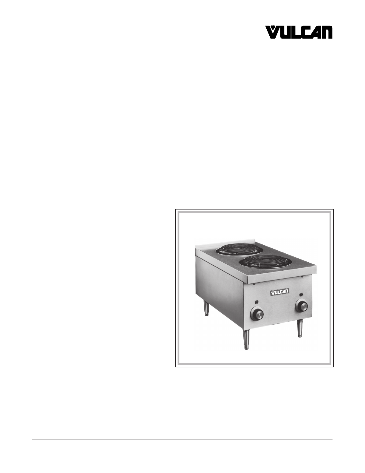
HOTPLATE
MODEL
MEH14
REPLACEMENT PARTS
VULCAN-HART COMPANY, P.O. BOX 696, LOUISVILLE, KY 40201-0696, TEL. (502) 778-2791
FORM 30971 (5-97)
Page 2
MEH14 HOTPLATE REPLACEMENT PARTS
1-2
6
5
42
41
40
26
25
24
3
4
18
19
20
21
22
17
8
9
7
10
11
X
Y
Z
14
15
16
12
13
39
38
37
36
35
© VULCAN-HART, 1997
23
29
30
27
28
31
32
33
34
PL-52127
MEH14 HOTPLATE
– 2 –
Page 3

REPLACEMENT PARTS MEH14 HOTPLATE
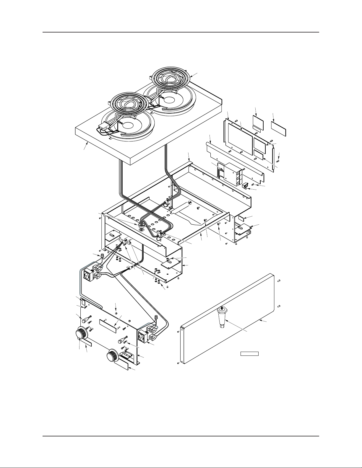
MEH14 HOTPLATE
ILLUS. PART
PL-52127 NO. NAME OF PART AMT.
1 00-920220-00011 Element W/Drip Pan & Ring (208V.) ..........................................................................................2
2 00-920220-00012 Element W/Drip Pan & Ring (240V.) ..........................................................................................1
3 00-920199 Rear Cross Member Assy. .........................................................................................................1
4 00-825126-00040 Block-Terminal ........................................................................................................................... 1
5 00-920207 Strip-Back Hold Down ................................................................................................................1
6 00-336215-00002 Screw-Arm .................................................................................................................................1
7 00-920222-00010 Label-Wiring Diagram ................................................................................................................1
8 00-825368 Plate-Serial Number .................................................................................................................. 1
9 00-805782 Label-Disconnect Power ............................................................................................................ 1
10 00-908805 Label-Ground Warning .............................................................................................................. 1
11 SD-036-61 Self-Tapping Screw 10-16 x
12 00-805780 Marker-Supply ........................................................................................................................... 1
13 SC-053-05 Mach. Screw 10-24 x 3⁄8 Truss Hd., Slotted ............................................................................... 2
14 FE-023-68 Lug-Solderless ...........................................................................................................................1
15 00-805727 Label-Ground Marker .................................................................................................................1
16 00-820114 Bracket Assy. ............................................................................................................................. 4
17 NS-044-09 Nut Assy. 10-24 Hex Keps......................................................................................................... 2
18 NS-011-07 Mach. Nut 6-32 Hex ...................................................................................................................1
19 00-920233 Tray-Top Drip .............................................................................................................................1
20 SC-053-05 Mach. Screw 10-24 x 3⁄8 Truss Hd., Slotted ............................................................................... 2
21 NS-044-09 Nut Assy. 10-24 Hex Keps......................................................................................................... 2
22 00-920205 Front Cross Member Assy. ........................................................................................................1
23 SC-053-05 Mach. Screw 10-24 x 3⁄8 Truss Hd., Slotted ............................................................................... 2
24 NS-044-09 Nut Assy. 10-24 Hex Keps......................................................................................................... 4
25 00-920097-00001 Conduit ...................................................................................................................................... 2
26 SC-053-05 Mach. Screw 10-24 x 3⁄8 Truss Hd., Slotted ............................................................................... 2
27 00-423047-00029 Panel-Side ................................................................................................................................. 2
28 00-804405 Leg - With Adjustable Foot ........................................................................................................ 4
29 NS-047-68 Lock Nut 1⁄8 ................................................................................................................................. 2
30 00-417700-00003 Nameplate .................................................................................................................................1
31 00-920221 Switch (240V.)(Infinite Heat) ...................................................................................................... 2
32 PB-004-69 Plug-Hole ...................................................................................................................................2
33 00-920550-00001 Front Panel Assy. ...................................................................................................................... 1
34 00-805782 Label-Disconnect Power ............................................................................................................ 1
35 00-344646-00001 Label ..........................................................................................................................................1
36 00-920396 Knob-Control ..............................................................................................................................2
37 00-906440-00013 Light-Red Signal ........................................................................................................................ 2
38 SD-036-61 Self-Tapping Screw 10-16 x 1⁄2 Slotted Truss Hd., Type B ........................................................ 4
39 00-086556-00001 Label ..........................................................................................................................................1
40 00-911501-00005 Connector-Wire ..........................................................................................................................1
41 FE-016-02 Bushing - Snap .......................................................................................................................... 1
42 00-920671-00001 Top Assy. ................................................................................................................................... 1
1
⁄2 Slotted Truss Hd., Type B ........................................................ 1
– 3 –
Page 4

MEH14 HOTPLATE REPLACEMENT PARTS
MEH14 ELECTRIC MEDIUM DUTY
COUNTER HOTPLATE
SERVICE
WARNING: THE HOTPLATE AND ITS PARTS ARE HOT. USE CARE WHEN OPERATING, CLEANING OR
SERVICING THE HOTPLATE.
WARNING: DISCONNECT ELECTRICAL POWER SUPPLY AND PLACE A TAG AT THE DISCONNECT
SWITCH TO INDICATE THAT YOU ARE WORKING ON THE CIRCUIT BEFORE PERFORMING ANY
SERVICE.
REPLACING PILOT "ON" LIGHT OR INFINITE (CONTROL) SWITCH
1. Remove both control knobs by grasping outer edge and pulling straight out, without twisting or turning.
2. Remove two screws at top of front panel. Pull the top edge to open.
3. Disconnect leads to pilot or infinite switch and remove the damaged component. Mark disconnected leads
to identify them.
4. Mount the new infinite switch with fasteners provided. The new pilot light is snapped into place from the front
of the panel.
5. Connect leads to their corresponding terminals on the new component. Check the completed circuit against
the circuit diagram on back of the hotplate.
7. Reverse steps 1 and 2 to close front panel.
REPLACING HEATING ELEMENT
1. Remove the heating element support projection from the notch in the element ring (located under the element
and secured to the element). Then push the element assembly toward the notch in the drip pan to dislodge
the spring clip from the element ring.
2. Maneuver the element and support assembly so that it can be pulled out of the drip pan along with its
connecting wires.
3. Lift out the drip pan.
4. Remove the element ring by grasping it with both hands and pulling straight up so that it snaps out of the top
panel opening.
5. Loosen the two screws at the end of the heating element and located on the side of the insulator block. Slide
the insulator block to expose the terminals
6. Disconnect the leads from the damaged element and reconnect them to the new element.
7. Slide the insulator block over the element terminals so that the threaded end of the screws are guided to slots
on the central web of the insulator block. Tighten screws securely to prevent the insulator block from sliding.
8. Reverse Steps 1-4 to reassemble, and put the hot plate back into operation.
FORM 30971 MAY 1997 PRINTED IN U.S.A.
– 4 –
 Loading...