

SERVICE MANUAL
GTS12 HEAVY DUTY ELECTRIC
GRIDDLE TOP
GTS12
This Manual is prepared for the use of trained Vulcan Service
Technicians and should not be used by those not properly qualified.
This manual is not intended to be all encompassing. If you have not
attended a Vulcan Service School for this product, you should read,
in its entirety, the repair procedure you wish to perform to
determine if you have the necessary tools, instruments and skills
required to perform the procedure. Procedures for which you do not
have the necessary tools, instruments and skills should be
performed by a trained Vulcan Service Technician.
The reproduction, transfer, sale or other use of this Manual, without
the express written consent of Vulcan, is prohibited.
This manual has been provided to you by ITW Food Equipment
Group LLC ("ITW FEG") without charge and remains the property
of ITW FEG, and by accepting this manual you agree that you will
return it to ITW FEG promptly upon its request for such return at
any time in the future.
A product of VULCAN Baltimore, MD 21222
F25446 (January 2012)

TABLE OF CONTENTS
TABLE OF CONTENTS
GENERAL ................................................................................3
Introduction ............................................................................ 3
Installation, Operation & Cleaning .......................................................... 3
Tools................................................................................. 3
Specifications .......................................................................... 3
REMOVAL AND REPLACEMENT OF PARTS .................................................... 4
Removing Griddle Top from Frame ......................................................... 4
Covers and Panels ...................................................................... 5
Lighted Switch Assembly ................................................................. 5
Power Cord............................................................................ 5
High Limit Cutoff Switch .................................................................. 6
Control Thermostat...................................................................... 7
Heating Element ........................................................................ 9
Arm Mechanism ....................................................................... 11
SERVICE PROCEDURES AND ADJUSTMENTS................................................. 13
Down Force Adjustment ................................................................. 13
Control Thermostat Test................................................................. 13
Heating Element Test ................................................................... 14
ELECTRICAL OPERATION ................................................................. 15
Component Function ................................................................... 15
Wiring Diagram........................................................................ 15
TROUBLESHOOTING ...................................................................... 16
© Vulcan 2012
F25446 (January 2012)
Page 2 of 16
GTS12 GRIDDLE TOP - GENERAL
GENERAL
INTRODUCTION
This manual is for the GTS12 Heavy Duty Electric
Griddle Top. Procedures in this manual will apply to
all models unless specified. Pictures and illustrations
will be of model GTS12-1 unless otherwise noted.
All of the information, illustrations and specifications
contained in this manual are based on the latest
product information available at the time of printing.
MODELS
GTS12-1 208V, Front Grease Trough
GTS12-2 240V, Front Grease Trough
GTS12-3R 208V, Rear Grease Trough
GTS12-4R 240V, Rear Grease Trough
INSTALLATION, OPERATION &
CLEANING
Refer to the Operation and Field Installation Manual
F38300 for specific installation, operation and
cleaning instructions.
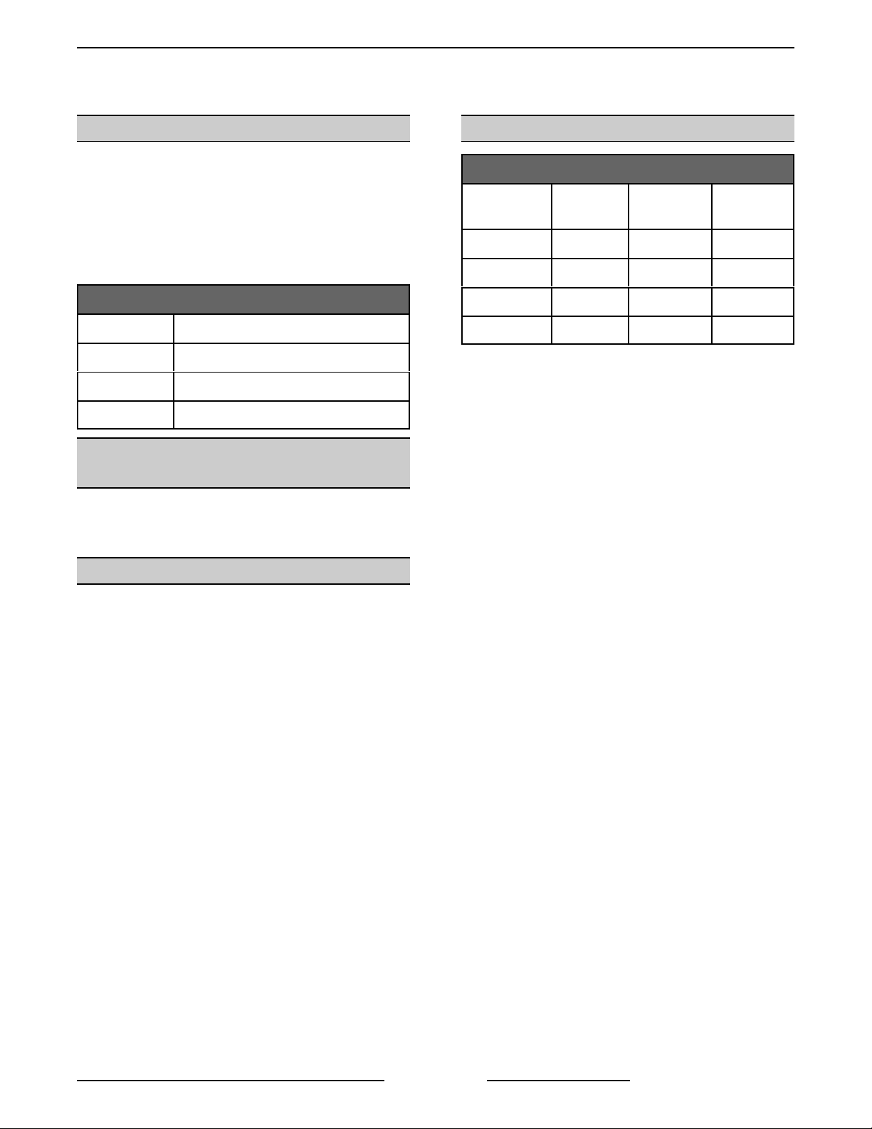
SPECIFICATIONS
ELECTRICAL SPECIFICATIONS
Model No. Voltage Power 1 Phase
Draw
GTS12-1 208 V 3.6 kW 17.3 A
GTS12-2 240 V 3.6 kW 15 A
GTS12-3R 208 V 3.6 kW 17.3 A
GTS12-4R 240 V 3.6 kW 15 A
TOOLS
Standard
• Standard set of hand tools.
• Metric set of hand tools.
• VOM with A/C current tester (any quality VOM
with a sensitivity of at least 20,000 ohms per
volt can be used).
Special
• Temperature tester (thermocouple type).
• Torque wrench (in.-lb.).
• Clamp on type amp meter.
Page 3 of 16
F25446 (January 2012)
GTS12 GRIDDLE TOP - REMOVAL AND REPLACEMENT OF PARTS
REMOVAL AND REPLACEMENT OF PARTS
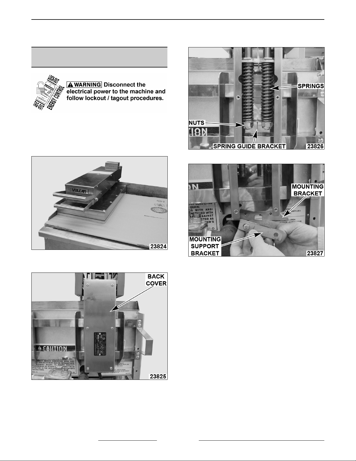
REMOVING GRIDDLE TOP
FROM FRAME
NOTE: Make sure that griddle top and griddle are
cool before servicing.
1. Place cardboard or other protective covering on
griddle surface to prevent scratching.
5. Remove 2 lower bolts.
2. Remove 6 screws and move back cover out of
the way.
3. Put griddle top in complete vertical position.
4. Remove 2 nuts, spring guide bracket and 2
springs.
A. Remove mounting support bracket and
mounting bracket.
6. Remove 2 upper bolts.
A. Remove mounting support bracket and
mounting bracket.
7. Remove griddle top from frame.
8. Reverse procedure to install.
9. Check for proper operation.
F25446 (January 2012) Page 4 of 16
GTS12 GRIDDLE TOP - REMOVAL AND REPLACEMENT OF PARTS
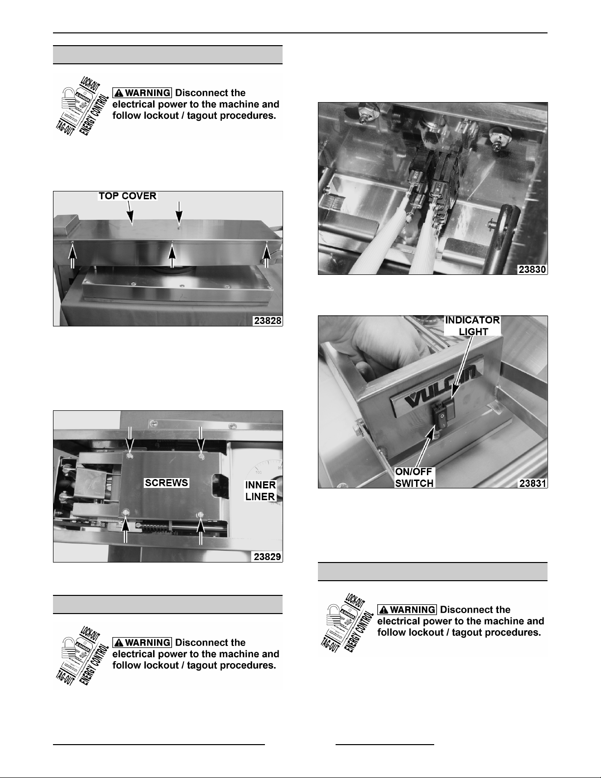
COVERS AND PANELS
Top Cover
1. Remove 7 screws and top cover.
2. Remove 4 screws and move INNER LINER out
of the way.
3. Remove electrical connections, noting their
locations.
4. Pinch clips and push lighted switch assembly
through.
2. Reverse procedure to install.
Inner Liner
1. Remove TOP COVER.
2. Remove 4 screws securing inner liner.
3. Reverse procedure to install.
LIGHTED SWITCH ASSEMBLY
5. Reverse procedure to install.
NOTE: Ensure that terminal connections are
completely seated and tight.
6. Check for proper operation.
POWER CORD
1. Remove TOP COVER.
1. Remove TOP COVER.
2. Remove 4 screws and move INNER LINER out
of the way.
F25446 (January 2012)Page 5 of 16

GTS12 GRIDDLE TOP - REMOVAL AND REPLACEMENT OF PARTS
3. Disconnect power cord from terminal block.
4. Remove back cover.
5. Transfer spring to replacement power cord.
6. Install retaining grommet onto new power cord
19" from tip of ring terminals.
6. Pull off thermostat knob and remove 2 screws.
Remove control thermostat body from inner
liner.
7. Install power cord.
8. Check for proper operation.
HIGH LIMIT CUTOFF SWITCH
1. REMOVE GRIDDLE TOP FROM FRAME.
2. Remove TOP COVER.
3. Remove 4 screws and move INNER LINER out
of the way.
4. Remove electrical connections from control
thermostat and high limit, noting their location.
5. Disconnect heating element wires from terminal
block.
7. Remove jam nut from around high limit reset
button. Remove high limit switch body from
inner liner.
8. Disconnect cooking head assembly ground
wires and remove 2 hex screws securing
universal joint to upper arm body.
NOTE: Bend down edges of locking washer.
9. Carefully separate upper arm assembly from
cooking head assembly.
NOTE: Be careful not to damage or pull the
thermostat and high limit probes that are still
attached in the cooking head.
F25446 (January 2012) Page 6 of 16

GTS12 GRIDDLE TOP - REMOVAL AND REPLACEMENT OF PARTS
10. For ease in servicing, remove knockout in upper
arm assembly. Pass high limit and control
thermostat through.
NOTE: Plastic ring must be used during reassembly.
11. Remove all 12 screws around perimeter of
cooking head assembly cover and 4 screws in
the center around the universal joint. Separate
cover from cooking head assembly.
backing out.
15. Check for proper operation.
CONTROL THERMOSTAT
1. REMOVE GRIDDLE TOP FROM FRAME.
2. Remove TOP COVER.
3. Remove 4 screws and move INNER LINER out
of the way.
4. Remove electrical connections from control
thermostat and high limit, noting their location.
A. Disconnect heating element wires from
terminal block.
12. Remove nuts and washers holding high limit
probe to insulation panel frame.
13. Remove high limit switch from griddle top.
14. Reverse procedure to install.
A. Bend up edges of locking washer to
prevent universal joint hex screws from
5. Pull off thermostat knob and remove 2 screws.
Remove control thermostat body from inner
liner.
6. Remove jam nut from around high limit reset
button. Remove high limit switch body from
inner liner.
F25446 (January 2012)Page 7 of 16

GTS12 GRIDDLE TOP - REMOVAL AND REPLACEMENT OF PARTS
7. Disconnect cooking head assembly ground
wires and remove 2 hex screws securing
universal joint to upper arm body.
NOTE: Bend down edges of locking washer.
8. Carefully separate upper arm assembly from
cooking head assembly.
NOTE: Be careful not to damage or pull the
thermostat and high limit probes that are still
attached in the cooking head.
11. Remove high limit probe and ground wire from
insulation panel frame.
9. For ease in servicing, remove knockout in upper
arm assembly. Pass high limit and control
thermostat through.
NOTE: Plastic ring must be used during reassembly.
10. Remove all 12 screws around perimeter of
cooking head assembly cover and 4 screws in
the center around the universal joint. Separate
cover from cooking head assembly.
12. Remove 4 center spacers and 12 nuts securing
insulation panel frame to heating element.
13. Remove insulation panel frame and insulation
panel.
14. Remove 16 jam nut, flange nut, lock washer
stacks securing pressure plate to heating
element.
F25446 (January 2012) Page 8 of 16

GTS12 GRIDDLE TOP - REMOVAL AND REPLACEMENT OF PARTS
15. Remove pressure plate and heating element.
16. Remove thermostat probe from ceramic
insulation strip in plate groove.
5. Pull off thermostat knob and remove 2 screws.
Remove control thermostat body from inner
liner.
17. Remove control thermostat from griddle top.
18. Reverse procedure to install.
A. Bend up edges of locking washer to
prevent universal joint hex screws from
backing out.
19. Check for proper operation.
HEATING ELEMENT
Removal
1. REMOVE GRIDDLE TOP FROM FRAME.
2. Remove TOP COVER.
3. Remove 4 screws and move INNER LINER out
of the way.
4. Remove electrical connections from control
thermostat and high limit, noting their location.
A. Disconnect heating element wires from
terminal block.
6. Remove jam nut from around high limit reset
button. Remove high limit switch body from
inner liner.
7. Disconnect cooking head assembly ground
wires and remove 2 hex screws securing
universal joint to upper arm body.
NOTE: Bend down edges of locking washer.
8. Carefully separate upper arm assembly from
cooking head assembly.
NOTE: Be careful not to damage or pull the
thermostat and high limit probes that are still
attached in the cooking head.
F25446 (January 2012)Page 9 of 16

GTS12 GRIDDLE TOP - REMOVAL AND REPLACEMENT OF PARTS
9. For ease in servicing, remove knockout in upper
arm assembly. Pass high limit and control
thermostat through.
NOTE: Plastic ring must be used during reassembly.
10. Remove all 12 screws around perimeter of
cooking head assembly cover and 4 screws in
the center around the universal joint. Separate
cover from cooking head assembly.
13. Remove insulation panel frame and insulation
panel.
14. Remove 16 jam nut, flange nut, lock washer
stacks securing pressure plate to heating
element.
11. Remove high limit probe and ground wire from
insulation panel frame.
12. Remove 4 center spacers and 12 nuts securing
insulation panel frame to heating element.
15. Remove pressure plate and heating element.
16. Remove the old cover gasket.
17. Remove thermostat probe from ceramic
insulation strip in plate groove.
Replacement
1. Ensure plate surface is clean and free of any
particles or defects that may prevent contact
between the heating element and plate.
2. Install control thermostat probe into groove of
plate with the ceramic insulation strip in place
above it.
F25446 (January 2012) Page 10 of 16

GTS12 GRIDDLE TOP - REMOVAL AND REPLACEMENT OF PARTS
3. Install new cover gasket.
4. Seat new heating element in place.
A. Transfer protective sleeve to new element
wires.
5. Install pressure plate and place a lock washer
on each element stud, then finger tighten a
flange nut on each lock washer.
6. Starting in the center of the element, tighten
each row of flange nuts to 20 in.-lbs. in the
following order.
ARM MECHANISM
Trigger Removal
1. Remove TOP COVER and move INNER LINER
out of the way.
2. Remove bolts, washers and plate nuts.
7. Install a top nut on each flange nut and torque
to 20 in.-lbs.
8. Reinstall insulation panel, insulation frame and
high limit probe.
NOTE: Only tighten nuts to 1/2 turn past finger tight.
Over tightening can fracture the insulation panel.
9. Reverse removal procedure to install.
A. Bend up edges of locking washer to
prevent universal joint hex screws from
backing out.
10. Check for proper operation.
3. Remove trigger from pins.
4. Reverse procedure to install.
A. Orient plate nuts so that groove is on top,
and rounded corner is towards handle.
Trigger Mechanism Removal
1. Remove trigger.
2. Remove e-clips and pins.
3. Disengage tie bars.
4. Unseat snap ring on one end, then push in
other end of mechanism to remove.
F25446 (January 2012)Page 11 of 16

GTS12 GRIDDLE TOP - REMOVAL AND REPLACEMENT OF PARTS
5. Reverse procedure to install.
Removing Mechanism From Arm Body
1. REMOVE GRIDDLE TOP FROM FRAME.
2. Remove TOP COVER and INNER LINER.
3. Remove e-clips and pins. Disengage tie bars.
2. Remove mechanism from arm body.
3. Remove slotted bolts from both sides.
4. Pull rods and remove springs.
5. Slide out locking plate.
6. Reverse procedure to install.
4. Remove power cord from terminal block and
remove back cover.
A. Remove 4 bolts from weld nuts.
5. Remove mechanism from arm body.
6. Reverse procedure to install.
Locking Plate Replacement
1. REMOVE GRIDDLE TOP FROM FRAME.
F25446 (January 2012) Page 12 of 16

GTS12 GRIDDLE TOP - SERVICE PROCEDURES AND ADJUSTMENTS
SERVICE PROCEDURES AND ADJUSTMENTS
DOWN FORCE ADJUSTMENT
1. Remove 6 screws and back cover.
2. Tighten (decreases down force) or loosen
(increases down force) both nuts evenly.
CONTROL THERMOSTAT TEST
1. Mount temperature tester probe in center of
griddle top plate, 8" down from the top edge.
2. Turn griddle top on and set to 350EF. Allow
thermostat to cycle 3 times to preheat.
3. Record temperature when indicator light turns
ON and OFF. Repeat for 3 cycles.
4. Calculate the temperature differential.
Differential = Indicator Light OFF - Indicator Light ON
Example: 365 - 340 = 25EF differential
A. Differential should be less than 50EF.
B. If differential is greater than 50EF, replace
control thermostat.
5. Calculate the average temperature.
Average Temperature =
Indicator Light OFF + Indicator Light ON
2
Example: 365 + 345 = 710 ÷ 2 = 355EF
6. If average temperature differs more than 50EF
from the dial setting, replace control thermostat.
3. Reinstall back cover once desired down force is
achieved.
F25446 (January 2012)Page 13 of 16

GTS12 GRIDDLE TOP - ELECTRICAL OPERATION
HEATING ELEMENT TEST
1. Measure voltage at heating element leads and
verify against data plate voltage.
A. If voltage is incorrect, find the source of the
problem.
B. If voltage is correct, check current draw
(amps) through the heating element lead
wires.
NOTE: This method is preferred over a resistance
check when a clamp on type amp meter is available.
2. If current draw is correct then heating element is
functioning properly. See table below for
proper values.
3. If current draw is not correct, turn griddle top
OFF and disconnect the electrical supply.
A. Replace heating element then proceed to
step 5.
4. If unable to check current draw, a resistance
check may indicate a malfunctioning element.
A. Disconnect electrical supply and remove
lead wires from heating element. Check
resistance (ohms). See table below for
proper values.
5. Check for proper operation.
VOLTS POWER AMPS OHMS
208
240
NOTES:
3.6 kW 17.3 12
3.6 kW 15 16
1. Values in table are nominal.
Tolerance is +5/-10%.
2. Resistance values (ohms) are
@ 77EF room temperature.
F25446 (January 2012)
Page 14 of 16

GTS12 GRIDDLE TOP - ELECTRICAL OPERATION
ELECTRICAL OPERATION
COMPONENT FUNCTION
Lighted Switch Assembly .... On/Off switch turns griddle top ON and OFF. Indicator light signals when
power is being cycled to heating element.
Control Thermostat ......... Monitors thermostat probe and cycles power to heating element.
High Limit Thermostat ....... Protects griddle top by cutting power to heating element if temperature goes
above 624EF.
Heating Element ............ Heat source for griddle top.
WIRING DIAGRAM
F25446 (January 2012)Page 15 of 16

GTS12 GRIDDLE TOP - TROUBLESHOOTING
TROUBLESHOOTING
SYMPTOM POSSIBLE CAUSE
Heat does not come on when power
switch is turned ON.
Heat does not come on when
thermostat is turned ON.
Unit will not lock or remain in the
raised position.
Unit will not lower from the raised or
locked position.
Unit will not raise from the cooking or
lowered position.
Food under-cooked. 1. Temperature set too low.
Food over-cooked. 1. Temperature set too high.
Food is being crushed. 1. Cooking surface pressing down too hard when in the lowered
Food sticks to cooking surface. 1. Temperature set too high or too low.
1. If power switch in not illuminated, check breaker panel and main
power supply.
2. High limit cutoff switch is tripped - depress reset button.
3. Thermostat set too low.
4. High limit is opened.
5. Power switch malfunction.
6. Thermostat malfunction.
7. Heating element malfunction.
1. Power switch not in the ON position.
2. High limit cutoff switch is tripped - depress reset button.
3. Power not supplied to unit.
4. Power switch malfunction.
5. Thermostat malfunction.
6. Heating element malfunction.
1. Lift by lower handle only. Do not squeeze upper and lower
handles together when raising.
2. Not raising high enough. Unit will only lock at the 47E and 90E
position.
3. Problem with locking mechanism or handles.
1. Lift slightly (to take weight off) then squeeze the upper and lower
handles together while lowering the unit.
2. Problem with locking mechanism.
1. Problem with locking mechanism.
2. Check that power cord is not binding.
2. Food issue, see operator manual.
3. Cooking surface not touching or partially touching food when in
the lowered position. Tension springs need to be adjusted.
2. Food cooked for too long of a time.
3. Cooking surface pressing down too hard when in the lowered
position. Tension springs need to be adjusted.
position. Tension springs need to be adjusted.
2. Cooking surface needs to be cleaned.
3. Cooking surface not covered with enough cooking oil.
Form 25446 (January 2012) PRINTED IN USA
 Loading...