

Page 1
INSTALLATION, SERVICE &
PARTS MANUAL FOR FRYCAT™
CATALYTIC GAS FRYERS
MODEL: CCFD-2C-KFC
VULCAN-HART CORPORATION, 3600 NORTH POINT BOULEVARD, BALTIMORE, MARYLAND 21222, TEL. (301) 284-0660
Page 2

OPERATING, INSTALLATION AND SERVICE PERSONNEL
Operating information for this equipment has been prepared for use by qualified and/or authorized operating
personnel.
All installation and service on this equipment is to be performed by qualified, certified, licensed and/or
authorized installation or service personnel, with the exception of any marked with a , in front of the part
number.
Service may be obtained by contacting the Factory Service Department, Factory Representative or Local
Service Agency.
DEFINITIONS
QUALIFIED AND/OR AUTHORIZED OPERATING PERSONNEL
Qualified or authorized operating personnel are those who have carefully read the information in this manual
and are familiar with the equipment's functions or have had previous experience with the operation of the
equipment covered in this manual.
QUALIFIED INSTALLATION PERSONNEL
Qualified installation personnel are individuals, a firm, corporation or company which either in person or
through a representative are engaged in, and are responsible for:
1. The installation of gas piping from the outlet side of the gas meter, or the service regulator when the meter
is not provided, and the connection and installation of the gas appliance. Qualified installation personnel
must be experienced in such work, be familiar with all precautions required, and have complied with all
requirements of state or local authorities having jurisdiction. Reference in the United States of America National Fuel Gas code ANSI Z223 1 (Latest Edition) In Canada-Canadian Standard CAN1-B149 1 NAT
GAS (Latest Edition) or CAN1-B149 2 PROPANE (Latest Edition).
2. The installation of electrical wiring from the electric meter, main control box or service outlet to the electric
appliance. Qualified installation personnel must be experienced in such work, be familiar with all
precautions required, and have complied with all requirements of state or local authorities having
jurisdiction. Reference In the United States of America-National Electrical Code ANSI NFPA No 70 (Latest
Edition) In Canada-Canadian Electrical Code Part 1 CSA-C22 1 (Latest Edition).
QUALIFIED SERVICE PERSONNEL
Qualified service personnel are those who are familiar with Vulcan equipment who have been endorsed by
the Vulcan-Hart Corporation. All authorized service personnel are required to be equipped with a complete
set of service parts manuals and stock a minimum amount of parts for Vulcan equipment.
SHIPPING DAMAGE CLAIM PROCEDURE
For your protection, please note that equipment in this shipment was carefully inspected and packed by
skilled personnel before leaving the factory. The transportation company assumes full responsibility for safe
delivery upon acceptance of this shipment.
If shipment arrives damaged:
1. VISIBLE LOSS OR DAMAGE — Be certain this is noted on freight bill or express receipt and signed by
person making delivery.
2. FILE CLAIM FOR DAMAGES IMMEDIATELY — Regardless of extent of damage.
3. CONCEALED LOSS OR DAMAGE — If damage is unnoticed until merchandise is unpacked, notify
transportation company or carrier immediately, and file 'concealed damage" claim with them. This should
be done within (15) days of date of delivery is made to you. Be sure to retain container for inspection.
We cannot assume responsibility for damage or loss incurred in transit. We will, however, be glad to
furnish you with necessary documents to support your claim.
PLEASE RETAIN THIS MANUAL FOR FUTURE REFERENCE
Page 3

IMPORTANT NOTES FOR ALL VULCAN APPLIANCES
1. These units are produced with the best possible workmanship and material. Proper installation is vital if best performance and
appearance are to be achieved. Installer must follow the installation instructions carefully.
2. Information on the construction and installation of ventilating hoods may be obtained from the "Standard for the installation of
equipment for the removal of smoke and grease laden vapors from commercial cooking equipment,” NFPA No 96 (latest edition)
available from the National Fire Protection Association, Battery March Park, Quincy MA 02269.
3. For an appliance equipped with a flexible electric supply cord, the cord is equipped with a three-prong (grounding) plug. This
grounding plug is for your protection against shock hazard and should be plugged directly into a properly grounded three prong
receptacle. Do not cut or remove the grounding prong from this plug If the appliance is not equipped with a grounding plug, and
electric supply is needed, ground the appliance by using the ground lug provided (refer to the wiring diagram).
(FOR GAS APPLIANCES ONLY)
4. Do not obstruct the air flow into and around the appliance. This air flow is necessary for proper combustion of gases and for
ventilation of the appliance. Provisions for ventilation of incoming air supply for the equipment in the room must be in accordance
with National Fuel Gas Code ANSI Z223.1 (latest edition).
5. Do not obstruct the flow of flue gases from the flue duct (when so equipped) located on the rear (or sides) of the appliance. It is
recommended that the flue gases be ventilated to the outside of the building through a ventilation system installed by qualified
personnel.
6. For an appliance equipped with casters, (1) the installation shall be made with a connector that complies with the Standard for
Connectors for Movable Gas Appliances, ANSI Z21.69 (latest edition), and Addenda, Z21. 69a (latest edition), and a quickdisconnect device that complies with the Standard for Quick-Disconnect Devices for Use With Gas Fuel, ANSI Z21.41 (latest
edition), and Addenda, Z21.41 a (latest edition) and Z21.41 b (latest edition), and (2) adequate means must be provided to limit
the movement of the appliance without depending on the connector and the quick-disconnect device or its associated piping to
limit the appliance movement.
If disconnection of the restraint is necessary, reconnect this restraint after the appliance has been returned to its originally
installed position.
7. The appliance and its individual shutoff valve must be disconnected from the gas supply piping system during any pressure testing
of that system at test pressures in excess of 1/2 psig (3.45 k Pa).
8. The appliance must be isolated from the gas supply system by closing its individual manual shutoff valve during any pressure
testing of the gas supply system at test pressures equal to or less than 1/2 psig (3.45 k Pa).
CAUTIONS
FOR YOUR SAFETY
DO NOT STORE OR USE GASOLINE OR OTHER FLAMMABLE VAPORS AND LIQUIDS IN
THE VICINITY OF THIS EQUIPMENT OR ANY OTHER APPLIANCE.
1. KEEP THE APPLIANCE FREE AND CLEAR FROM ALL COMBUSTIBLE SUBSTANCES.
2. IN THE EVENT A GAS ODOR IS DETECTED, SHUT UNIT(S) DOWN AT THE MAIN
SHUTOFF VALVE AND CONTACT THE LOCAL GAS COMPANY OR GAS SUPPLIER FOR
SERVICE.
3. POST IN A PROMINENT LOCATION, INSTRUCTIONS TO BE FOLLOWED IN THE EVENT
THE SMELL OF GAS IS DETECTED. THIS INFORMATION MAY BE OBTAINED FROM A
LOCAL GAS SUPPLIER.
Page 4
WARNINGS . . .
FROM THE TERMINATION OF THE
REFERENCE: ANSI/NFPA
96-1984 4
-
1.2.2.2.
OF THE NATIONAL FIRE
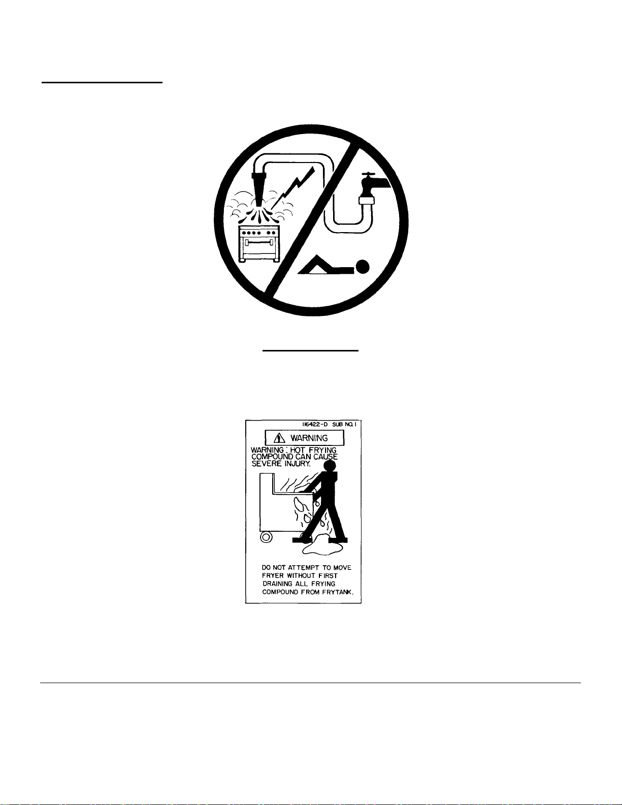
DO NOT SPRAY LIQUIDS OR VAPORS ON OR NEAR
WARNING:
EQUIPMENT UTILIZING ELECTRICITY
APPLIANCE FLUE VENT TO THE
FILTERS OF THE HOOD VENTING
SYSTEM, AN 18 INCH MINIMUM
CLEARANCE MUST BE MAINTAINED.
PROTECTION ASSOCIATION, INC., BATTERYMARCH PARK, QUINCY, MA
02269, AND NATIONAL BUILDING CODE 1976 SEC. 1015.7b (2) OF THE
AMERICAN INSURANCE ASSOCIATION. ENGINEERING AND SAFETY
SERVICE, 85 JOHN STREET, NEW YORK, NY 10038
116696-5
Page 5

IMPORTANT NOTES
1. Vulcan units are produced with the best possible workmanship and material. Proper installation is vital if best
performance and appearance is to be achieved. Installer must follow the installation instructions carefully.
2. Keep the appliance area free and clear from all combustible substances,
3. For an appliance equipped with a flexible electric supply cord, the cord is equipped with a three prong (grounding)
plug. This grounding plug is for your protection against shock hazard and should be plugged directly into a three
prong receptacle. Do not cut or remove the grounding prong from this plug. If the appliance is not equipped with a
grounding plug, and electric supply is needed, ground the appliance by using the ground lug provided (refer to the
wiring diagram).
4. Retain this manual for future reference.
IMPORTANT
THIS EQUIPMENT IS DESIGN CERTIFIED BY A NATIONALLY
RECOGNIZED TESTING LABORATORY TO THE
APPROPRIATE NATIONAL STANDARDS AS INDICATED ON
THE EQUIPMENT RATING PLATE. ANY MODIFICATION
WITHOUT WRITTEN PERMISSION OF VULCAN-HART
CORPORATION VOIDS CERTIFICATION AND WARRANTY OF
THIS UNIT.
5. CAUTION: Post in a prominent location, instructions to be followed in the event the smell of gas is detected. This
information may be obtained from a local gas supplier.
6. Do not obstruct the air flow into and around the appliance. This air flow is necessary for proper combustion of gases
and for ventilation of the appliance. Provisions for ventilation and incoming air supply for the equipment in the room
must be in accordance with National Fuel Gas Code ANSI-Z223.1-1984.
7. Do not obstruct the flow of flue gases from the flue duct (when so equipped) located on the rear, sides or top of the
appliance. It is recommended that the flue gases be ventilated to the outside of the building through a ventilation
system installed by qualified personnel.
8. All CCFD-2C-KFC fryers are to be installed with a 6" clearance at the sides and rear adjacent to combustible
construction.
NOTE: An 18" minimum clearance must be maintained when placing a fryer next to adjacent to or behind an open top
flame unit.
9. The unit wiring diagram is packed in a clear plastic Ziploc bag placed within the fryer tank and also printed on the last
page of the CCFD-2C-KFC fryer installation, service and parts manual. A wiring diagram decal may be found
mounted on the inside left hand body side, just beyond the door area.
116696-6
Page 6

INSTALLATION, SERVICE & PARTS MANUAL
FRYCAT™ GAS FRYER MODEL CCFD-2C-KFC INDEX
Your Vulcan fryer is produced with the best possible workmanship Proper usage and maintenance will result in many
years of satisfactory performance.
DESCRIPTION PAGE
The manufacturer suggests that you thoroughly read this entire
manual and carefully follow all of the instructions provided.
DEFINITIONS OF PERSONNEL (Operating, Installation & Service) and
SHIPPING DAMAGE CLAIM PROCEDURES
Warranty Information 116696-3
Cautions 116696-4 thru -5
Important Notes 116696-6
Installation for Units on Casters 116696-8
Uncrating Instructions 116696-9
Electrical Connection 116696-9
Gas Supply Connection 116696-9
Installation Procedures to Verify Fryer Operation 116696-10
Computer Mounting Installation Procedures 116696-10 thru -11
Switch Panel Controls 116696-11
Adding Shortening 116696-11
Initial Operation Instructions 116696-12
Cleaning 116696-12
Blower Motor 116696-12
Door Switch 116696-12
Blower Air Adjustment 116696-13
Foam Pre-Filter Cleaning 116696-13
Ignitor Modules 116696-14
Ignitor Module Reset 116696-14
Setting Ignitor Location 116696-14
High Limit Control 116696-14
Suggestions for Care and Cleaning 116696-14
Removal of Control Box Housing 116696-15 thru -16
Troubleshooting Guides 116696-17 thru -21
Replacements Parts List & Photographs 116696-22 thru -32
Replacements Parts List & Exploded View 116696-33 thru 35
Wiring Diagram 116696-36
Revision Page (Inside Back Cover)
(Inside Front Cover)
SERVICE NOTE:
DO NOT ATTEMPT TO REMOVE SPARK IGNITORS OR BURNERS WITHOUT
CONSULTING VULCAN-HART SERVICE DEPARTMENT.
TELEPHONE: 1-800-638-2474
CAUTION: ELECTRICIAN
CONTINUITY OF ELECTRICAL GROUND TO WHICH THIS APPLIANCE WILL BE
CONNECTED MUST BE CONFIRMED. SEVERE DAMAGE TO ELECTRONIC
COMPONENTS CAN OCCUR AS A RESULT OF INADEQUATE GROUNDING.
116696-7
Page 7
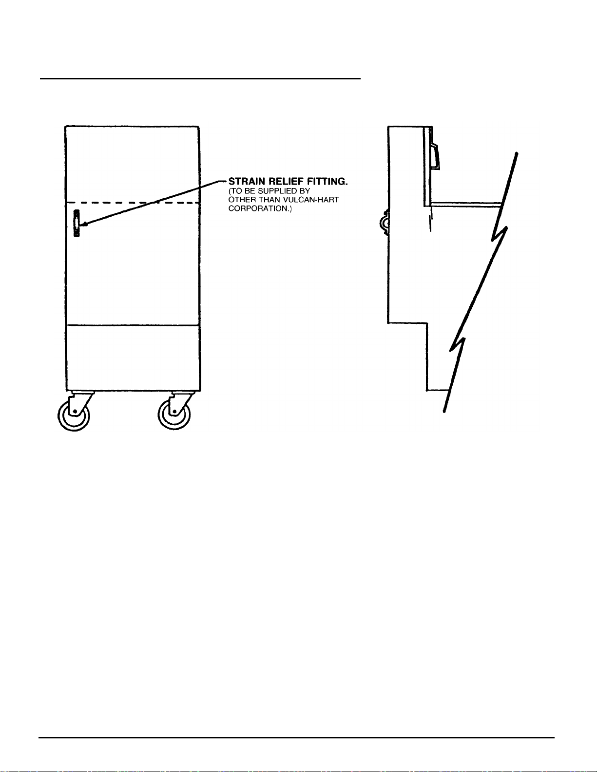
INSTALLATION FOR UNITS ON CASTERS
NOTE: All units on casters must be installed with a gas connector that complies with the American
National Standard ANSI Z21.69-1979 for movable gas appliances.
UNITS MOUNTED ON CASTERS UTILIZING A FLEX HOSE AND QUICK DISCONNECT GAS
CONNECTION MUST BE INSTALLED WITH RESTRAINING DEVICE AT ALL TIMES. THE
RESTRAINING DEVICE IS TO BE SUPPLIED BY OTHER THAN VULCAN-HART
CORPORATION.
If necessary, appliance strain relief may be disconnected when moving unit for cleaning. However,
caution must be taken that the gas supply has been turned off and disconnected. Reconnect
harness prior to the reconnecting of the gas supply and restoring unit to position and operation.
116696-8
Page 8
UNCRATING INSTRUCTIONS
DETAIL A
116696
-
9
The following procedure should be followed when uncrating all CCF fryers.
NOTE: Personnel required to perform uncrating proce-
dure (2).
1. Place crated unit in open area near to final installation
locality.
2. Using band cutters, carefully remove (2) outer crating
straps.
3. Unfold cardboard crate top and remove (4) cardboard
cover protector sleeves.
4. Lift cardboard crate shell from unit.
5. Using band cutters, carefully remove (2) inner crating
straps.
6. Remove (2) cardboard protector sleeves from top right
and left hand tank sides.
7. Remove clear plastic protective cover from unit.
ELECTRICAL CONNECTION
Improper grounding and/or polarity will result in lock out
of unit and eventual damage to the ignition systems. The
unit is supplied with a 10 foot long 3 wire supply cord.
This appliance is equipped with a 3 prong (grounding)
8. Carefully lift unit styrofoam support block and wood
crating platform, then gently rest unit onto the floor.
9. Check unit packaging in areas indicated for the
following items:
FRYER TANK
A. Instruction Manual Packet (1).
B. Wiring Diagram Packet (1).
C. Clean-Out Rod (1).
D. Basket Supports (2).
E. Drain Pipe (1).
Items missing from the above packing list may be
obtained by contacting the local area Vulcan parts
depot or the Vulcan-Hart Corporation, Baltimore,
Maryland - Division Parts Department.
10. Discard crating materials.
11. Gently lift unit front and carefully wheel fryer to final
installation location.
plug for your protection against shock hazard and should
be plugged directly into a properly grounded three prong
receptacle. DO NOT cut or remove the grounding prong
from this plug. (DETAIL A)
GAS SUPPLY CONNECTION
For proper functioning of the CCF catalytic fryers, a gas
main feed inlet pressure of at least 5.0" W.C. (Water Column) but not more than 8.75" W.C. must be maintained
for natural gas while the unit is in operation. A gas main
feed inlet pressure of at least 12.0" W.C. but not more
than 13.0"W.C. must be maintained for propane gas
while the unit is in operation.
The pressure regulator setting of the CCFD-2C-KFC fryer
is 3.0"W.C. for natural gas and 9.0" W.C. for propane
gas.
When connecting unit to gas supply, installation
personnel must install this equipment in accordance with
all state and local authorities having jurisdiction. Refer to
inside front cover of manual under qualified personnel,
ITEM NO. 1.
All gas supply connections and any pipe joint compound
used must be resistant to the action of propane gases.
Pipe joints should be tested for leaks with a soap and
water solution before operating unit. (DETAIL A)
Page 9
INSTALLATION PROCEDURES TO VERIFY
FRYER OPERATION
After making all electrical and gas connections, verify
fryer operation before installing computer as follows:
NOTE: An independent gas shut-off valve is supplied
within the fryer unit location to the rear of the gas
manifold system connecting to the 1/2" inlet gas pipe. This
shut-off valve must be in open position for proper unit
functioning.
1. Clean fryer tank as stated within the K.F.C. C.O.M.
and fill melted shortening to 1/2" below the vat full
mark.
2. Packing fryer vat with solid shortening
A. Remove basket rack supports.
B. Place solid cube of shortening to the rear of the
fryer tank. On split vat models be sure to push
cube down over the center divider in equal
sections.
C. Chop shortening cube up and pack shortening
well all around the heat exchanger tubes and
thermistor probe(s).
D. Replace basket rack supports in correct position
on top of the packed solid shortening.
E. Turn unit on and place unit into fat melt operation.
HAZARD NOTE: Failure to pack solid shortening as
described above may result in vat fire. Caution
should be taken and fryer should not be left
unattended.
3. Close fryer doors.
4. Check left side vat operation first by pushing left side
power switch to "ON" position. Verify fryer operation
and turn left vat side "OFF".
5. Check right side vat operation by pushing right side
power switch to "ON". Verify right side fryer operation.
6. Push left side power switch back "ON" and verify
simultaneous operation of both vats.
7. Allow fryer to operate for two to three minutes.
8. Shut fryer "OFF" and unplug electric supply. This completes fryer operation check out. NOTE: If fryer fails to
operate during any of the above procedures, verify
gas supply, electrical connections and refer to VulcanHart troubleshooting instructions.
COMPUTER MOUNTING INSTALLATION PROCEDURES
After verifying fryer operation, mount the computer panel
separately supplied by Stratford Control Systems, Inc. to
the CCFD-2C-KFC fryer following the instructions below:
1. Remove computer from shipment package.
2. Remove (2) black screws and (2) tinnerman nuts from
the right (RT.) and left (LT.) hand sides of the
computer panel.
3. Place clip section of tinnerman nuts (1 ea.) onto the
RT. & LT. hand fryer control housing frame. (See
Detail B).
DETAIL C
6. Align tinnerman nuts and computer mounting holes.
7. Reinstall black screws to the RT. and LT. hand sides
of the computer panel. Be sure screws are tightly secured. (See Detail D).
DETAIL B
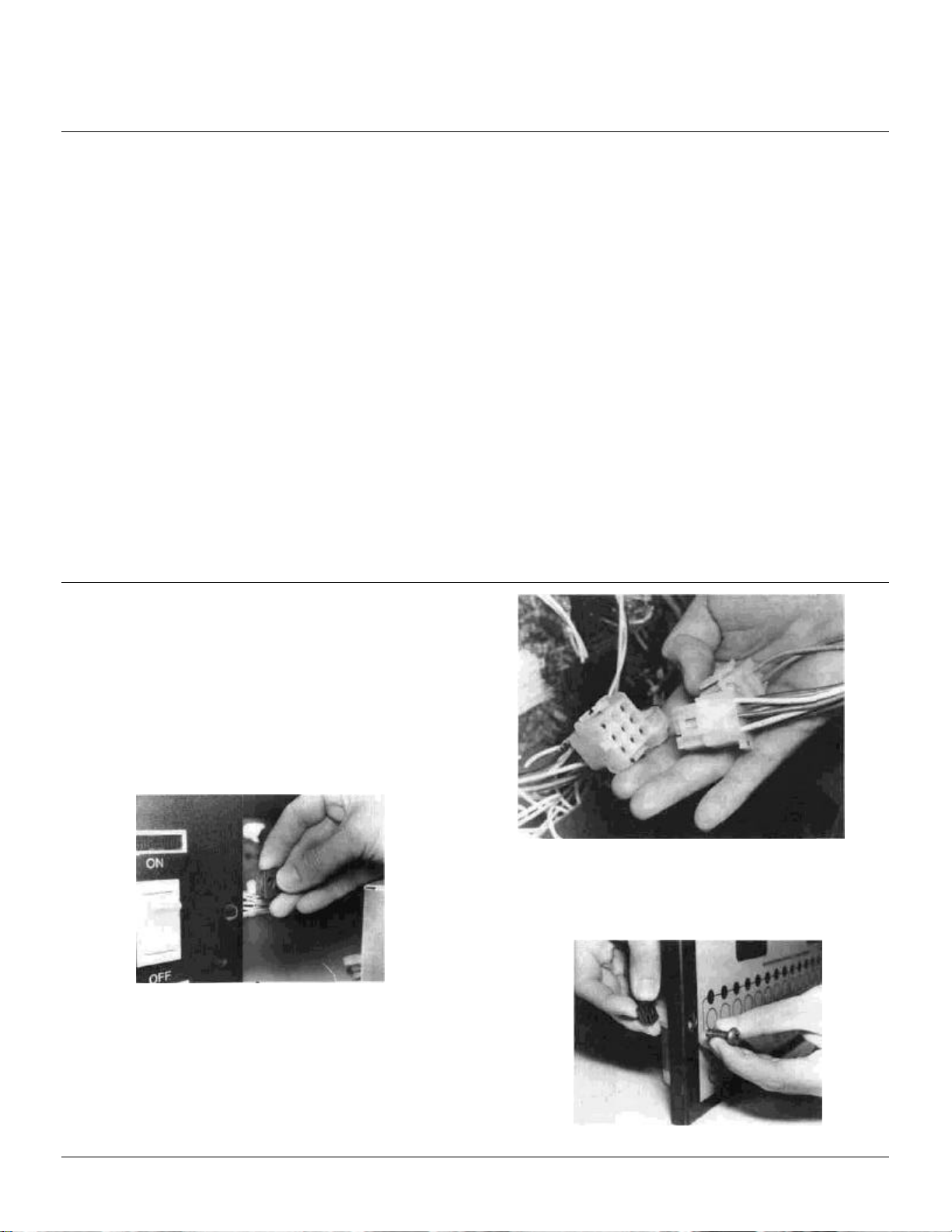
4. Connect (2) sets of wiring harness cables (1 set for
LT. vat and 1 set for RT. vat.) supplied with the fryer
to the plugs provided on the rear of the computer
panel. (See Detail C).
5. Insert computer panel into the rectangular spacing
provided in the control housing frame.
116696-10
DETAIL D
Page 10
COMPUTER MOUNTING INSTALLATION PROCEDURES
116696
-
11
NOTE: Check (FAST) operating instructions to verify cor-
rect computer installation and operation procedures.
8. Verify computer operation as follows:
A. Close fryer doors and plug in fryer electrical supply
cord.
B. Push right and left vat power switches to "ON".
C. Allow unit to heat up to frying temperature.
NOTE: If computer display reads LO-R or LO-L, the fryer
is in the automatic melt mode and the burner may not
come on immediately. When unit reaches programmed
frying temperature, computer display will indicate cooking
mode as described in the (FAST) computer operation instructions.
D. This completes the computer check-out procedure.
NOTE: If computer does not operate properly, refer
to (FAST) troubleshooting instructions.
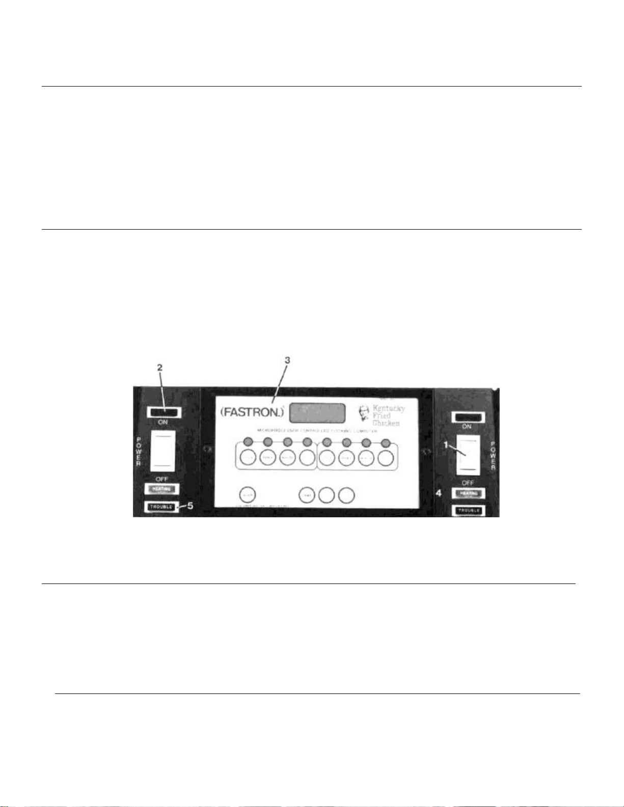
SWITCH PANEL CONTROLS CCFD-2C-KFC
1. Power Switch "ON-OFF" - Controls electric supply to
unit.
2. Panel "ON" Light - Light "ON" indicates that electric
supply is functioning.
3. Microprocessor Controlled Cooking Computer -
Preprogramming device which, when activated, controls unit frying modes. (Computer supplied by other
than Vulcan-Hart Corp.) (See Detail E).
4. Heating Light - When "ON" indicates that the temperature controller is calling for gas to the burner.
5. Trouble Light - When "ON" indicates that ignition device has locked out (reset required). NOTE: To reset,
turn power switch "OFF" then "ON".
DETAIL E
ADDING SHORTENING
REFER TO CONFIDENTIAL OPERATION MANUAL.
See also pg. 10 of this manual (Packing fryer vat with solid shortening).
Page 11
INITIAL OPERATION INSTRUCTIONS
DETAIL F
116696
-12
1. Push power supply rocker switch to "ON" position.
NOTE: Gas line service valve must be in "OPEN"
position and all power supply cords and harness cables
must be connected to the unit power source for
operational functioning. The independent gas shut-off
valve supplied within the unit located to the rear of the
unit manifold system connecting to the 1/2" inlet pipe
must be in the open position for proper unit operation.
NOTE: If the shortening temperature is less than 185°F
the fryer is in the automatic melt mode and the burner
During the first few "ON" pulses, the trouble indicator
light may come on indicating no ignition due to air in the
gas line. If this happens, turn the rocker switch off and
then back on and try again.
For service or extended shutdown, turn service valve to
"CLOSED" position, push unit power supply rocker
switch to "OFF" position and disconnect power supply
cord from main power source.
The above information may also be found on the inside
fryer door panel.
may not come on immediately. In this mode, the burner
pulses "ON" 4 seconds and "OFF" 26 seconds.
CLEANING__________________________________________________
New fryer tanks must be cleaned before filling with shortening.
REFER TO KFC CONFIDENTIAL OPERATION MANUAL.
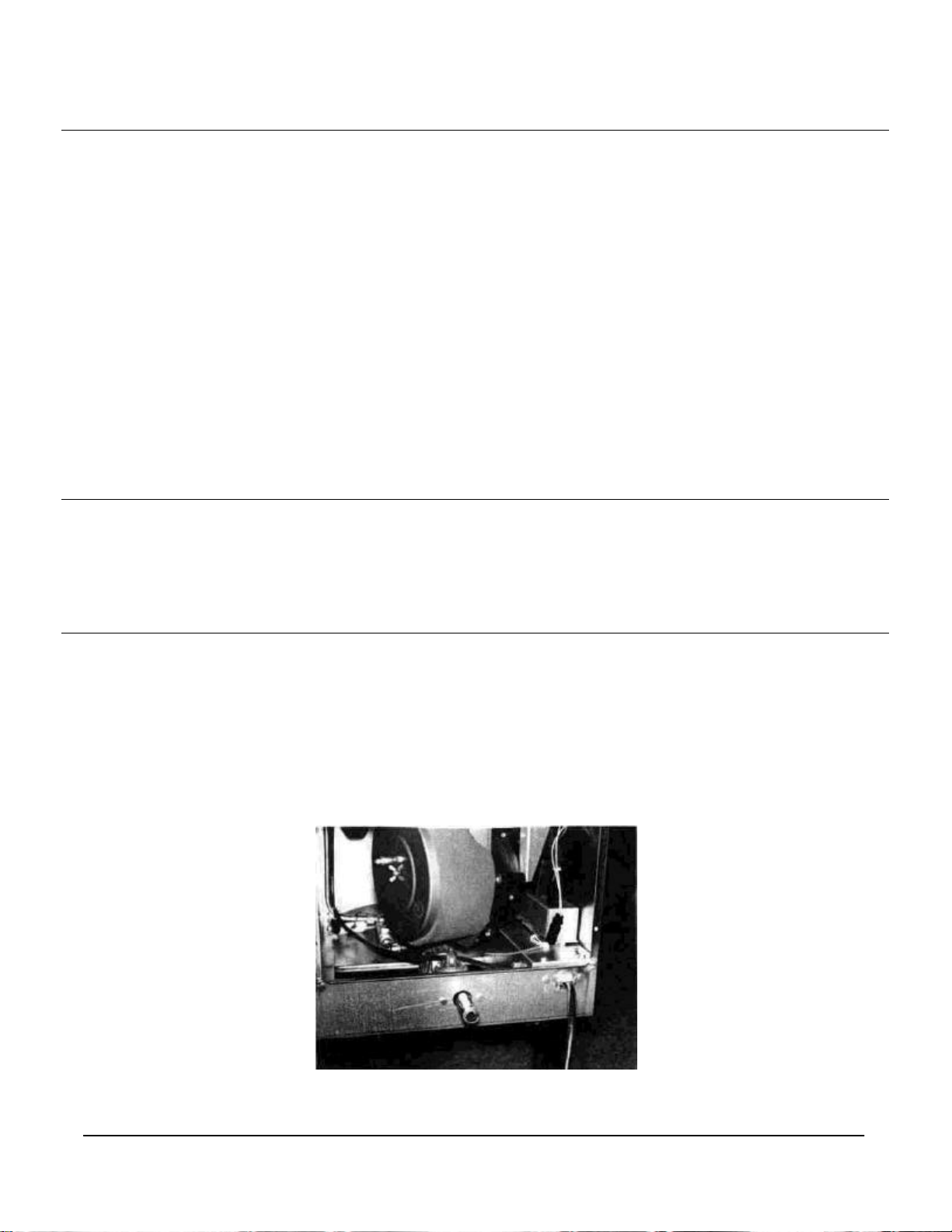
BLOWER MOTOR
CCFD-2C-KFC series fryers are equipped with a factory
installed blower motor. Proper operation of the blower
motor is vital to the fryer performance. The blower motor
is the main source of air flow servicing the burner ignition
system.
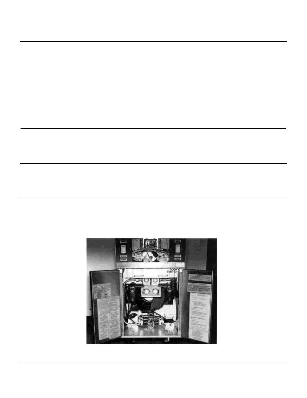
DOOR SWTICH
Each CCFD-2C-KFC fryer is equipped with a door safety
switch that will automatically shut the unit down when the
fryer door is opened. However, operating and service
personnel should NOT rely on door switch to shut unit
down while working inside the door panel control area.
WARNING: Do not rely on door switch to shut unit power
down. Push fryer power switch to "OFF" before entering
the inside door panel control area for filtering or servicing.
By-passing the fryer door switch should be done by
service personnel only. (See Detail F).
Page 12

BLOWER AIR ADJUSTMENT
NOTE: The critical air adjustment for each burner has
been factory tested and set. Further adjustment should
not be required unless the fryer is being installed above
2,000 ft. elevation or burner or fan replacement has been
made. If air adjustment is necessary, contact local
service agency. (Refer to color trend guide chart.)
NOTE: All CCFD-2C-KFC series fryers are equipped with
an air filter. This filter must be in place at all times during
unit operation. Failure to use air filter will result in unit
breakdown and will automatically void all warranties
associated with the unit.
The air filter is a critical part of the unit functioning and
should be checked frequently. Clean foam pre-filter when
soiling becomes apparent.
FOAM PRE-FILTER CLEANING
To clean CCF series pre-filters, follow steps 1 thru 7 from
air filter replacement of windjammer or swirlwind blower
systems below. After removing filter element assembly,
detach the gray foam pre-filter from the filter element.
Wash foam piece out in lukewarm water using a mild
CYLINDRICAL (SOLBERG) AIR FILTER REPLACEMENT FOR USE
WITH WINDJAMMER OR SWIRLWIND BLOWER SYSTEMS
CONSTRUCTED AFTER 2-9-87
NOTE: Blower air filter is serviceable from rear of unit only. (Refer to Detail G. - Refer also to blower air adjustment
notation above and page 13 of KFC Manual 116697-G1).
To replace blower air filter, follow the steps below:
1. Push power switch to "OFF".
2. Disconnect filter receptacle.
3. Disconnect power supply cord.
4. Disconnect gas supply, if necessary to make unit accessible from rear.
5. Remove wing nut from blower mounting bracket.
6. Remove filter cover cap from blower mounting bracket.
7. Remove filter from blower mounting bracket.
8. Check replacement filter element. Be sure gray pre-filter covers entire surface of filter element.
9. Install filter onto blower mounting bracket. (Turn until very tight.)
10. Install filter cover cap securely with flanged side against filter assembly. NOTE: Cap must be tightly fitted
against filter assembly to insure proper filtration of dust particles.
11. Reinstall wing nut to blower mounting bracket.
12. Reconnect gas supply and power supply line.
13. Reposition fryer and connect filter receptacle.
14. Push power switch to "ON" position and continue with normal unit operating procedures.
soap solution. Rinse with cool water and ring dry. Evenly
reinstall the gray foam pre-filter over the entire filter element. To reinstall filter element assembly onto the unit,
follow steps 8 thru 14 from air filter replacement of
windjammer or swirlwind blower systems below.
DETAIL G
116696-13
Page 13

CCFD-2C-KFC UNIT IGNITOR MODULES
INTERFACE BOARDS, IGNITORS, BURNER, HIGH LIMIT
AND TANK PROBE FUNCTIONS
1. Igniter Modules: An electrode module (2 required per
unit) which accepts electric signals from the interface
board to energize the spark igniters.
2. Igniters: An electronic device which passes an ignition spark to ignite the fryer burners (2 required per
unit).
3. Burners: Fibermatrix heat exchanging device which
provides the main source of infrared type heat for fryer
operation.
4. High Limit Control: An electronic device that will shut
the unit down in the event of thermostat failure. The
operating temperature of the high limit control is 435°F
or 60°F (223.8°C or 15.5°C) higher than the highest
temperature allowed by the thermostat. In the event of
a high limit "shut-down", the entire control system will
be put out of operation. DO NOT attempt to restart the
IGNITOR MODULE RESET
The igniter module reset system protects the igniter modules from overloads.
If trouble light illuminates immediately after the power
fryer until the shortening temperature has lowered to
approximately 350°F (176.6°C). CAUTION: If this
situation continually occurs, DO NOT attempt to
bypass the high limit. Shut unit down and contact an
authorized factory service agency.
5. High Limit Probe: An electronically actuated device
mounted through the right side of the front tank wall
which senses the shortening temperature to allow the
high limit monitoring of unit over heating conditions.
6. Thermistor Probe: An electronically actuated device
mounted through the tank front wall which senses
shortening temperature allowing the temperature
control board to monitor unit heating.
7. Interface Board: A back-up temperature controlling
circuit board that will allow fryer to operate in the event
the computer controller were to fail.
switch is activated, turn fryer power switch "OFF", and back
"ON". If after second attempt, fryer continues to malfunction,
turn fryer "OFF" and contact service agency.
SETTING IGNITOR LOCATION
This setting will provide optimum ignition reliability and
prevent igniter module lockout. The igniter location is factory set and should not require adjustment unless the
igniter has been replaced or has been knocked out of
adjustment.
Should adjustment become necessary, contact local service agency.
HIGH LIMIT CONTROL
The function of high limit control is to shut the unit down
in the event of a thermostat failure which would allow the
cooking oil to be overheated. The operating temperature
of the high limit control is 435°F or 60°F (223.8°C or
15.5°C) higher than the highest temperature allowed by
the thermostat.
In the event of a high limit "shutdown", the entire control
system will be put out of operation.
DO NOT attempt to restart the fryer until the temperature
of the cooking oil has lowered to approximately 350°F
(176.6°C).
If the situation continually occurs, do not attempt to
bypass the high limit. Shut unit down and contact a
service agency.
SUGGESTIONS FOR CARE AND CLEANING
REFER TO KFC CONFIDENTIAL OPERATION MANUAL.
116696-14
Page 14

REMOVAL OF CONTROL BOX HOUSING
15
For servicing of computer panel, igniter module, interface
boards; follow steps A1 thru A3.
For removal of igniters, high limit, burners or probes, follow
steps A1 thru A9.
NOTE: During servicing before installing any new probe,
A1. Remove (2) screws from the top left (LT.) and right
(RT.) hand (HD.) corners of the control panel front.
(Photo A1).
wrap probe threaded end with Teflon tape to prevent tank
leakage.
To remove computer panel or gain access to reset button,
igniter modules and interface boards:
A3. Detach the computer panel assembly from the fryer
body. If complete removal is desired, disconnect (2 sets
for LT. SD. vat and (1) set for RT. SD. vat) wiring
harness plugs. Panel may now be completely removed to
access computer or igniter modules and interface
boards. (Photo A3)
A2. Open fryer doors and remove (2) screws located beneath the lower front channel RT. and LT. HD. sides.
(Photo A2)
To service igniter burners, assemblies, high limit and
tank probes, remove control housing following steps A4
thru A9 on page 16.
116696-
Page 15
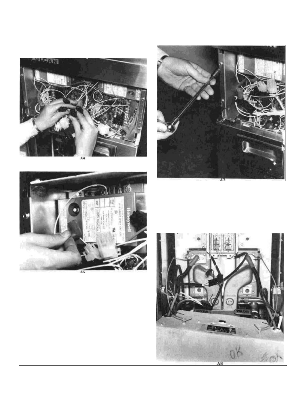
REMOVAL OF CONTROL BOX HOUSING (Cont.)
A4. Disconnect all remaining wire leads and igniter wires
from the control area. (Photos A4 & A5)
A5. Disengage (4) screws positioned along the RT. and
LT. hand control housing box front side flanges. (Photo
A7)
A6. Disengage (4) screws securing housing to high limit
bracket.
A7. Disconnect high limit wire connector plug.
A8. Remove housing box assembly from fryer frame. Dis-
connect main power wire harness plug and (2) green ignitor module ground wires (photo A8). Now housing may
be completely removed from unit. This will allow complete
servicing access to the burners, ignitors, high limit and
unit tank probes.
116696-16
Page 16

TROUBLESHOOTING GUIDE
CAUTIONS
• Be sure air filters are properly in place at all times.
• When reinstalling control box, be sure not to pinch wiring between control box and burner tubes. Be sure
ignitor ground (green) wires are connected to the (2) 1/4" tabs on the back of the box.
• When connecting interface harness to P.C. boards, do not exert excessive force, board damage may result.
• When removing or installing ignitors, do not allow ignitor to brush against burner. Permanent burner damage
may result.
• Refer to wiring diagram C116597-2.
• WARNING: Blower relay turns on 120 volt A.C. to blower. Be sure fryer is "unplugged" when working with
blower and blower relay wiring.
WHEN TROUBLESHOOTING, THE FOLLOWING QUICK CHECK SHOULD BE DONE FIRST TO DETERMINE IF
PROBLEM IS DUE TO COMPUTER MALFUNCTION OR FRYER MALFUNCTION.
1. Push unit power switch to "OFF" on both left and right side of control panel.
2. Disconnect unit electric supply.
3. Remove (2) screws securing computer panel.
4. Disconnect both sets of computer wire harnesses. (1) set
for left side vat and (1) set for right side vat.
5. Reconnect unit electrical supply.
6. Verify fryer operation using steps 1 thru 7 described in the installation procedures section of this manual.
NOTE: Upon completion of the above check, if fryer operation seems normal then problem area has been
isolated to a computer malfunction.
If fryer is not operating properly, refer to the following pages for possible troubleshooting solutions.
IMPORTANT TO READ FIRST
116696-17
Page 17

TROUBLESHOOTING GUIDE (Cont.)____________________________
Before servicing this equipment, read through the applicable sections in their entirety and read all "CAUTIONS"
at the beginning of this guide.
PROBLEM CAUSE REMEDY
LOUD IGNITION
NO HEAT
Improper gas pressure (Nat. gas) Manifold regulator pressure should be set
at 3.0" W.C. main feed pressure should
not drop below 5.0" W.C.
(Propane gas) Main manifold pressure should be set at
9.0" W.C. and main feed pressure should
not drop below 11.0" W.C.
Air Adjustment Adjust air so that burner is at full intensity
within 3 seconds.
Defective high voltage ignitor wire Replace high voltage lead.
Defective ignitor Allowing spark leakage or intermittent
spark. Replace ignitor. (Sparking can be
clearly heard when listening at front of unit
with door open.)
Improper spark gap Check and set gap to. 160".
Obstructed ignitor Remove ignitor, check ignitor gap for
burner particles or carbon, clean off
particles and reinstall ignition.
Door switch malfunction Be sure door switches are activating when
doors are closed. (When doors are open,
pull out door switch posts to activate and
observe operation.)
No electrical power
Check for 110V supply to fryer.
Check for 24V grounded ignition system
power. Check for 24V AC to ground at
wire #1 of both power switches. If no
voltage, then check for AC voltage
input/output at rear most transformer.
Check for 24 VAC isolated "computer"
power between wires # 16 & # 17 on both
interface boards. If no voltage, check for
AC voltage input/output of forward most
transformer.
Make sure all wiring harness connectors
are engaged and locked in place.
116696-18
Page 18
TROUBLESHOOTING GUIDE (Cont.)
PROBLEM CAUSE REMEDY
NO HEAT (Cont.) Malfunctioning sensors Check thermistor probe terminations
on "back-up" interface P.C. boards. Be
sure terminations are not touching or
shorted. Probe terminations are
labeled on P.C. boards as "PRB-1" and
"PRB-2" (two terminals each) remove
one or both PRB-1 wires. Measure
OHMS resistance through the wires. If
fryer is cold, resistance is about 100-K
OHMS. If reading is infinity-probe is
defective-replace probe. If reading is
zero-check wires for a direct short,
replace probe if necessary. Repeat
this procedure and check PRB-2 wires.
NOTE: PRB-2 is probe connection
for computer.
PRB-1 is probe connection
for back-up interface control.
Computer & back-up interface If computer is displaying "PROB" or
system has no display, check interface
harness (from computer to interface
P.C. boards) to be sure all connectors
are properly engaged and check
connectors to be sure all pins are
securely in place. If harness seems
to be in proper condition, but computer
still displays "PROB", refer to
"Malfunctioning sensors". Disconnect
computer wiring harness from P.C.
boards. Fryer should operate on
back-up temperature control. This
would indicate a defective computer or
computer interface. Replace as
required. If unit still fails to operatecheck for 24V supply across terminal
#5 and #6 of back-up interface
board. If power supply is confirmedreplace P.C. board.
TROUBLE LIGHT "FLASHES" Normal operation
THEN "HEATING" LIGHT COMES ON
TROUBLE LIGHT COMES ON Indicates power to ignitor module Check 3A fuse on ignitor module. If
AND STAYS ON input, but no power out. bad, look for short circuit or ground
on ignitor board output (overload)
before replacing fuse.
Defective ignitor module. Replace.
116696-19
Page 19

TROUBLESHOOTING GUIDE (Cont.)_____________________________
section.
PROBLEM CAUSE REMEDY
TROUBLE LIGHT "ON"
No gas
No air supply
Improper air supply If air adjustment is way off, either too
Improper or no burner flame If burner is lighting, but a blue flame is
Check "in-house" plumbing for shut-off
valves and fire protection valves to be
sure they are open.
Be sure flexible hose is connected to fryer.
Be sure shut-off valve in fryer is open.
Be sure solenoid wires are securely
connected, and supplying 24V when fryer
calls for heat.
Check for blower operation - voltage
supply, harness connections, jammed
wheel blower or defective motor. Replace
if necessary.
Check blower relay for normal operation.
Blower relay energizes when either left or
right power switch is turned on. Replace if
defective (24 VAC coil).
much or too little, burners may not ignite -
adjust air as required.
present, check air filter-replace if
necessary. If problem still exists, take the
following steps:
• Check blower for proper operation.
• Check gas pressure and air adjustments
as described in the "Loud Lighting"
Second high limit open
Loss of flame sense Make sure green ground wires of ignitor
• If burner won't brighten, replace burner.
Make sure 2nd hi-limit plugs are locked in
place.
Make sure hi-limit switches are closed (If
oil temp. is below 435°F.)
boards are seated to their terminals on
ignitor boards. Check for proper electrode
grounding. (See troubleshooting guide
"Cautions").
116696-20
Page 20

TROUBLESHOOTING GUIDE (Cont.)____________________________
116696
-21
PROBLEM CAUSE REMEDY
UNIT HAS NO FAT MELT CYCLE Computer is inoperative and unit is
operating on "back-up" interface board
Make sure computer harnesses are
attached.
Refer to "Malfunctioning Sensor" section.
NOTE: If above checks OK, then replace
computer.
COMPUTER (INTERMITTENT)
Bad computer connections Faulty
harness.
General wiring problems related to
interface wire harness.
Check for pins not seated in connections. FRYER OPERATING WITHOUT
Check for connectors to be mated and
locked in position.
Page 21

REPLACEMENT PARTS LIST & PHOTOGRAPHS
REPLACEMENT PARTS LIST AND PHOTOGRAPHS
FOR CCFD-2C-KFC SERIES FRYERS
WARNING ALL SERVICE PERSONNEL
WHEN SERVICING THIS EQUIPMENT, USE ONLY CERTIFIED (U.L. OR A.G.A.)
CONTROLS, DUPLICATING THOSE ORIGINALLY SUPPLIED ON THIS EQUIPMENT BY
VULCAN-HART CORPORATION
DO NOT SUBSTITUTE COMPONENTS WITH DIFFERENT MODEL NUMBER
DO NOT SUBSTITUTE COMPONENTS WITH DIFFERENT MANUFACTURING NAMES
DO NOT SUBSTITUTE COMPONENTS WITH REBUILT CONTROLS WITHOUT AUTHORIZATION FROM VULCAN-HART CORP.
ANY UNAUTHORIZED SUBSTITUTION OF CONTROLS AS STATED ABOVE MAY BE A SAFETY HAZARD AND WILL
AUTOMATICALLY VOID THE WARRANTY AND THE CERTIFICATION ASSOCIATED WITH THIS EQUIPMENT.
REPLACEMENT PARTS ORDERS:
The following information must accompany a replacement parts order or it cannot be filled:
A. Model and Serial Number.
B. Type of Gas.
C. Unit Voltage, Amperage and Motor Phase.
D. Appliance Finish Black, Grey, Stainless steel, etc.
This information may be found on the unit rating plate located inside the fryer door panel.
Parts may be ordered from your dealer, service agency or parts distributor. For information concerning parts ordering location
contact:
VULCAN-HART CORPORATION
VULCAN-HART CANADA 3600 NORTH POINT BLVD. OR
79 WEST STREET, SOUTH BALTIMORE, MD 21222 ORILLILA, ONTARIO L3V 6K5
SERVICE NOTE:
DO NOT ATTEMPT TO REMOVE SPARK IGNITORS OR BURNERS WITHOUT CONSULTING VULCAN-HART SERVICE
DEPARTMENT: TELEPHONE: 1-800-638-2474
CAUTION: ELECTRICIAN
CONTINUITY OF ELECTRICAL GROUND TO WHICH THIS APPLIANCE WILL BE CONNECTED MUST BE CONFIRMED.
SEVERE DAMAGE TO ELECTRONIC COMPONENTS CAN OCCUR AS A RESULT OF INADEQUATE GROUNDING.
116696-22
Page 22

PARTS LIST (Cont.)__________________________________________
ITEM NO. PART NO. DESCRIPTION QUANTITY
1 115801-G3 Fryer Tank 1
2 116675-G1 LT. Body Side 1
2A 116675-G2 RT. Body Side (NS) 1
3 116493-G1 Front Top Assembly 1
4 116480-G9 Frame Control Panel Assembly 1
5 116527-D1 Control Panel Mylar 1
6 114123-G5 Panel Assembly Door Front (RT. HD.) 1
6A 114123-G4 Panel Assembly Door Front (LT. HD.) 1
7 115843-G2 Leg Assembly 4
8 110118-22 Caster 2
9 113112-5 Leg 9" 2
73 114211-1 Door Handle 2
116696-23
Page 23

PARTS LIST (Cont.)
ITEM NO. PART NO. DESCRIPTION QUANTITY
4 116480-G9 Frame Control Panel Assembly 1
5 116527-D1 Decal Control Panel 1
10 111496-E13 Light-28V Heating 2
11 111496-E10 Light-28V Trouble 2
12 111496-E8 Light-Single Red 2
13 111496-B1 Power Switch 2
116696-24
Page 24

PARTS LIST (Cont.)__________________________________________
ITEM NO. PART NO. DESCRIPTION QUANTITY
14 116475-G1 Modular Control Box 1
15 116011-1 Ignitor Module 24V 2
16 116012-1 Board Interface 2
17 114151-4 Relay 24V VAC (NS) 1
17A 116535-1 Relay 24V DC 2
18 114145-2 Second High Limit 2
19 06089 Ground Lug 1
20 114149-8 Ignitor Cable 2
21 115207-1 Mini Cooling Fan 1
22 See Note Below Fuse Ignitor Module 2
23 113840-2 Mini Cooling Fan Thermal Disc (NS) 1
24 115977-2 Mini Fan Cover 1
NOTE: Ignitor module fuse is a standard 250 volt 3 amp fuse obtainable through any good local hardware store or
service agency.
116696-25
Page 25

PARTS LIST (Cont.)__________________________________________
ITEM NO. PART NO. DESCRIPTION QUANTITY
18 114145-2 Second High Limit 2
20 114149-8 Ignitor Cable 2
25 116724-1 Tube Flex (Ignitor Cable) 2
26 114141-3 Thermistor Probe 2
27 116616-1 Sight Glass Cover 2
28 115517-1 Sight Glass 2
29 116446-2 Air Mixing Chamber (LT. HD.) 1
29A 116446-1 Air Mixing Chamber (RT. HD.) 1
30 114715-018-A1 Ignitor Wire to Module (Ground Lead) 2
33 114700-4 Male Straight CC Fitting 3/8" x 1/2" 2
116696-26
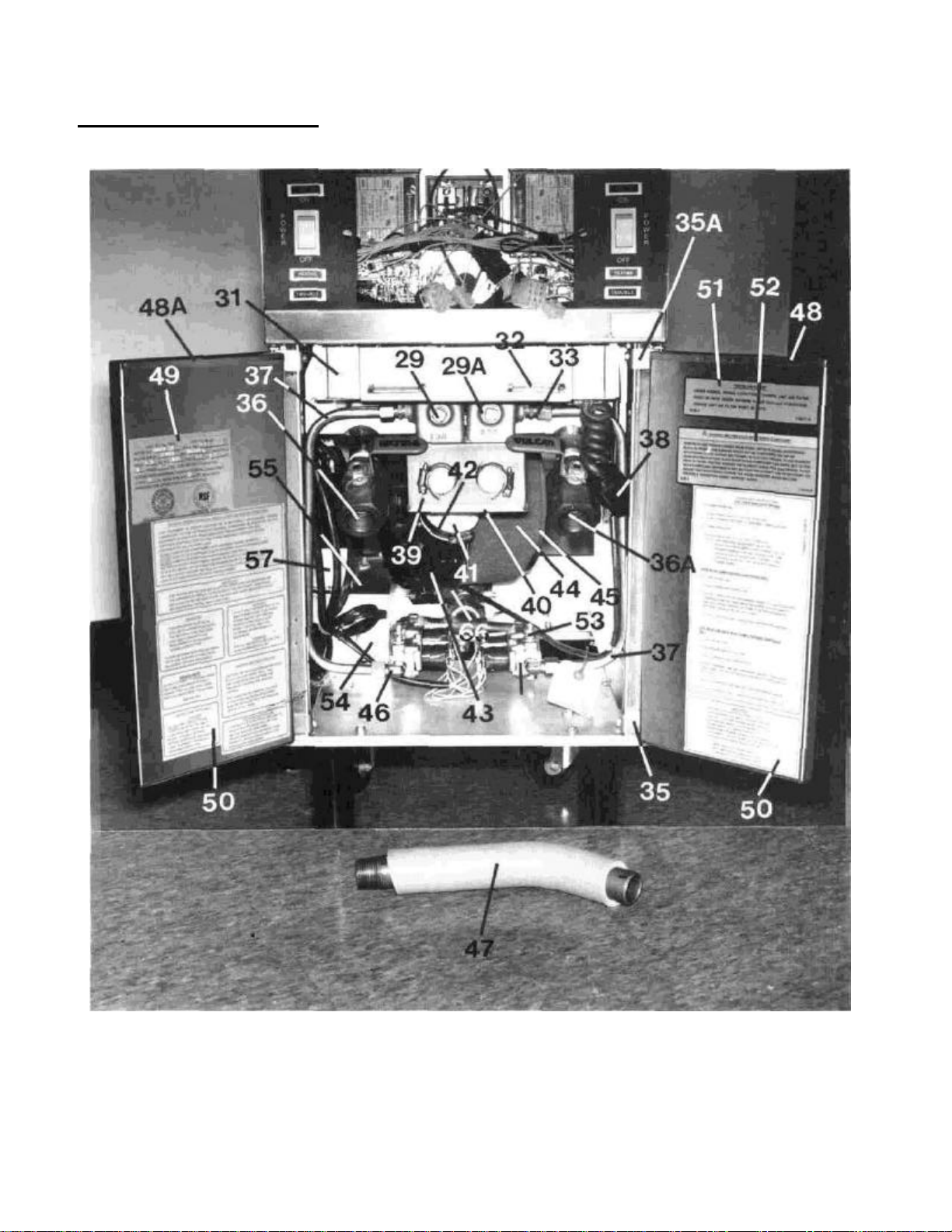
Page 26

PARTS LIST (Cont.)___________________________________________
ITEM NO. PART NO. DESCRIPTION
17 114151-4 Relay 24 VAC (NS)
29 116446-2 Air Mixing Chamber (LT. HD.)
29A 116446-1 Air Mixing Chamber (RT. HD.)
31 111496-F2 Door Switch
32 115887-1 Magnet
33 114700-4
34 109290-29 Orifice Spud #29 (Natural) (NS) SELECT AS 2
34A 109290-47 Orifice Spud #47 (Propane) (NS) REQUIRED 2
35 112780-5 Door Hinge (Bottom)
35A 112780-6 Door Hinge (Top)
36 114212-3 Drain Valve (LT. HD.)
36A 114212-4 Drain Valve (RT.HD.)
37 115734-1
38 115998-3 Cord Receptacle
39 115735-G2 Box Assembly Air Adjustor
40 115787-2 Cover, Air Adjustor
41 116640-1 Hose, Primary Air
42 115481-3 Clamp Hose
43 116673-1 Blower Swirlwind
43A 116673-3 Blower Windjammer (SELECT) 1
44 116660-3 Filter Solberg
45 116637-2 Cap, Filter
46 114800-2
47 116656-1 Drain Pipe
48 114123-G5 Door Panel Assembly (RT. HD.)
48A 114123-G4 Door Panel Assembly (LT. HD.)
49 115606-1 Rating Plate
50 116504-D Important Door Decal
51 116516-D1 Fryer Air Filter Decal
52 116576-D Solid Shortening Compound
53 104738-2 Pressure Tap
54 116525-G1 Transformer Base Assembly
55 116526-1 Transformer Cover
56 111500-12 Transformer 40 VA (NS)
57 116478-1 Housing Relay
65 3.0127-3 Filter Cap Wing Nut
66 116642-G1 Blower Filter Bracket
Male Straight CC Fitting 3/8" x 1/2"
Burner Tube 1/2"
Elbow 1/2"- 90°
QUANTITY
1
1
1
2
2
2
2
2
1
1
2
1
1
1
1
2
1
1
1
2
1
1
1
1
1
1
1
1
1
1
1
1
1
116696-27
Page 27
PARTS LIST (Cont.)
116696-28
Page 28

PARTS LIST (Cont.)
ITEM NO. PART NO. DESCRIPTION
46 114800-2 Elbow 1/2" x 3/8" -90°
58 111497-F8 Valve Automatic
59 113500-C6 Pipe Nipple 3/8" x 3/4" long
53 104738-2 Pressure Tap
60 12901 Nozzle
61 114678-1 3/8" Elbow Compression
62 113500-C16 Nipple 3/8 NPT, 2" long
63 114789-7 Tee
64 113500-D7 Close Nipple 1/2" x 1 1/8" long
67 116653-1 Pipe 1/2 NPT
68
68A
69 108604-3 Valve, Shut-Off 1/2 NPT
70 116653-G1 Pipe Inlet Gas 3/4" NPT Assembly
108279-1
108279-3
Regulator (Natural)
Regulator (Propane) (NS)
3/8 x 3/8 x 1/2 NPT
(SELECT)
QUANTITY
2
4
2
3
2
2
2
1
1
1
1
1
1
1
116696-29
Page 29

PARTS LIST (Cont.)
ITEM NO. PART NO. DESCRIPTION QUANTITY
1 115801-G3 Frytank Assembly 1
18 114145-2 Second High Limit 2
26 114141-3 Thermistor Probe 2
116696-30
Page 30

PARTS LIST (Cont.)___________________________________________
ITEM NO. PART NO. DESCRIPTION QUANTITY
8 110118-22 Casters (NS)
43 116673-1 Blower Swirlwind
44 116660-3 Filter Solberg
55 116526-1 Transformer Cover
57 116478-1 Housing Relay
68
68A
69 108604-3 Valve, Shut-Off 1/2 NPT
70 116653-G1 Pipe Inlet Gas 1/2" NPT Assembly
71 116293-D Warning Heat Shield - Decal
45 116637-2 Cap Filter
65 3.0127-3 Filter Wing Nut
73 105016-1 115 Volt Elec. Supply Cord
74 114109-2 Body Back
108279-1
108279-3
Regulator (Natural)
Regulator (Propane)
(SELECT)
1
1
1
1
1
1
1
1
1
2
1
1
1
1
116696-31
Page 31

PARTS LIST (Cont)
ITEM NO. PART NO. DESCRIPTION QUANTITY
18 114145-2 Second High Limit 2
20 114149-8 Ignitor Cable 2
72 114608-G1 Clean-Out Rod Assembly 1
116696-32
Page 32

PARTS LIST (Cont.)___________________________________________
ITEM NO. PART NO. DESCRIPTION QUANTITY
1 116654-1 Body Bottom, Front
2 116655-1 Body Bottom, Rear
3 116675-G1 Body Side Assembly, Left Hand
4 116675-G2 Body Side Assembly, Right Hand
5 114123-G5 Panel Assembly Door, Right Hand
6 114123-G4 Panel Assembly Door, Left Hand
7 112780-6 Hinge Door, Top
8 112780-5 Hinge Door, Bottom
9 115887-1 Magnet Door
10 116525-G1 Base Assembly Transformer
11 111500-12 Transformer 40VA
12 116526-1 Cover Transformer
13 114151-4 Relay 24 Volt (AC)
14 116478-1 Housing Relay
15 113112-5 Leg,9"
16 115843-G2 Leg Assembly
17 110118-22 Caster, 3"
18 105016-1 Supply Cord 115V
19 30314-3 Cord Grip
20 115452-G7 Manifold Assembly
21 114232-G5 Sub-Manifold Assembly
22 108604-3
23 108279-14 Regulator (Nat) Select 1
24 111497-F8 Solenoid Valve 24 Volt
25 115734-1 Burner Tubing
26 114800-2 CC Fitting 90° Elbow
27 114700-4 CC Fitting Straight
28 109290-29 Fitting Orifice (Nat) Select 2
29 116446-1 Tube Air Mixer, Rt Hd
30 116446-2 Tube Air Mixer, Lt Hd
30A 115784-1 Gasket, Air Mixer Tube (NS)
30B 115785-1 Gasket, End Cap (NS)
31 114799-3
32 115735-2 Box Assembly Air Adjuster
32A 115541-2 Gasket Foam 3M Tape (NS)
33 115787-2 Cover Air Adjuster
34 114706-2 Sleeve Air Adjuster
35 114703-3 Plunger Air Adjustor
36 116110-1 Plate Mounting Burner, Lt Hd
37 116110-2 Plate Mounting Burner, Rt Hd
38 115941-1 Insulation Burner Mounting (NS)
39 116616-1 Cover Sight Glass
40 115518-1 Sight Glass
41 115519-1 Insulation Sight Glass (NS)
42 116214-2 Ignitor
42A 115815-2 Gasket Ignitor
43 116155-2 Wedge, Ignitor
116696-33
108279-15 Regulator (LP)
109290-47 Fitting Orifice (LP)
Shut Off Valve, 1/2" NPT
Pipe Plug 3/8"
1
1
1
1
1
1
2
2
2
1
2
1
1
1
2
2
2
1
2
1
1
1
1
4
2
2
2
2
1
1
2
2
2
1
1
1
2
2
1
1
2
2
2
2
2
4
2
Page 33

PARTS LIST (Cont.)___________________________________________
ITEM NO. PART NO. DESCRIPTION
44 116751-G3 Burner Assembly, Lt Hd
45 116751-G4 Burner Assembly, Rt Hd
46 115783-G1 Burner
47 115801-G3 Tank Assembly
47A 116774-1 Insulation, Tank Front (NS)
47B 114616-C16 Insulation, Tank Bottom 1" (NS)
47C 116314-1 Insulation, Tank Rear 1/2" (NS)
48 114212-3 Valve Drain, Lt Hd
49 114212-4 Valve Drain, Rt Hd
50 116490-1 Housing High Limit
51 116491-1 Bracket Guides, High Limit Housing
52 114145-2 Second High Limit Control
53 116510-1 Insulation, High Limit (NS)
54 115226-3
55 114141-3 Prope Dual Thermistor
56 116650-G1 Flue Box Assembly
56A 1166775-1 Insulation Flue Box (NS)
57 114152-5 Bottom Flue
58 114109-2 Back Upper Body
59 115885-G2 Flue Cap Assembly
60 116673-3 Blower (Fasco) Select 1
60A 116727-1 Gasket (Fasco) (NS) Select 1
61 116725-1 Tube PVC Blower (NS)
62 116640-1 Hose, Primary Air
63 115481-3 Clamp, Hose
64 116642-G3 Blower Support Assembly
65 116660-3 Filter Solberg
66 116818-1 Pre-Filter
67 116637-2 Cap Filter
68 30127-3 Nut-Wing
69 104738-2 Tap Pressure
70 116475-G1 Control Box Modular
71 116509-1 Insulation, Control Box (NS)
72 115207-1 Fan Cooling
73 116732-1 Bracket Fan
74 115977-2 Cover Fan
75 113840-2 Disc Thermal (NS)
76 115998-3 Cord Receptacle
77 116011-1 Board Ignitor
78 116012-1 Board Interface
79 114149-8 Cable Ignitor (HV)
80 116724-1 Tube Flex (HV)
81 06089 Lug Ground
82 116484-4 Control Box "Fascia"
83 111496-F2 Switch Interlock
84 116493-G1 Front Top Assembly
85 116527-D1 Decal Control Panel
116696-34
116673-1 Blower (Ametex)
116753-1 Gasket (Ametex) (NS)
Fitting 1/4 NPT x 3/16 CC (Swagelock)
QUANTITY
1
1
2
1
1
1
1
1
1
1
2
2
1
4
2
1
1
1
1
1
1
1
1
1
2
1
1
1
1
1
4
1
1
1
1
1
1
1
2
2
2
2
2
1
2
1
1
Page 34

PARTS LIST (Cont.)
ITEM NO. PART NO. DESCRIPTION QUANTITY
86 111496-B1 Rocker Switch 2
87 111496-E10 Light Trouble "Red" 2
88 111496-E13 Lighting Heater "Amber" 2
89 111496-E8 Light Signal "Red" 2
90 116480-G9 Control Panel 1
91 116813-1 Pressure Tap Plug 1
116696-35
Page 35

WIRING DIAGRAM
 Loading...