

Page 1
SERVICE MANUAL
SALAMANDER BROILERS
RADIANT AND INFRARED
VULCAN 36RB
36IRB
WOLF C36RB
C36IRB
This Manual is prepared for the use of trained Vulcan Service
Technicians and should not be used by those not properly
qualifi ed.
This manual is not intended to be all encompassing. If you have
not attended a Vulcan Service School for this product, you should
read, in its entirety, the repair procedure you wish to perform to
determine if you have the necessary tools, instruments and skills
required to perform the procedure. Procedures for which you
do not have the necessary tools, instruments and skills should
be performed by a trained Vulcan Service Technician.
The reproduction, transfer, sale or other use of this Manual,
without the express written consent of Vulcan, is prohibited.
This manual has been provided to you by ITW Food Equipment
Group LLC (“ITW FEG”) without charge and remains the property
of ITW FEG, and by accepting this manual you agree that you will
return it to ITW FEG promptly upon its request for such return
at any time in the future.
For additional information on Vulcan-Hart Company or to locate an authorized
parts and service provider in your area, visit our website at www.vulcanequipment.com
VULCAN-HART
DIVISION OF ITW FOOD EQUIPMENT GROUP, LLC
www.vulcanequipment.com
BALTIMORE, MD 21222
F45530 (0814)
Page 2

SALAMANDER BROILERS RADIANT AND INFRARED
TABLE OF CONTENTS
GENERAL .................................................................................................. 3
INTRODUCTION ....................................................................................... 3
INSTALLATION, OPERATION AND CLEANING ......................................................... 3
RACK POSITION AND GAS SETTING .................................................................. 3
MODELS ............................................................................................... 3
SPECIFICATIONS ...................................................................................... 3
LUBRICATION ......................................................................................... 3
TOOLS ................................................................................................. 3
REMOVAL AND REPLACEMENT OF PARTS ............................................................... 4
MANIFOLD COVER .................................................................................... 4
TOP PANEL ASSEMBLY ............................................................................... 4
LEFT SIDE PANEL ..................................................................................... 4
RIGHT SIDE PANEL .................................................................................... 5
CONTROL VALVES (36RB/C36RB) ..................................................................... 6
PILOT (36RB/C36RB) .................................................................................. 6
RADIANT BURNER (36RB/C36RB) ..................................................................... 7
CONTROL VALVES (36IRB/C36IRB) ................................................................... 8
PILOT (36IRB/C36IRB) ................................................................................. 9
INFRARED BURNER (36IRB/C36IRB) ................................................................. 10
GAS PRESSURE REGULATOR ....................................................................... 12
RACK SPRINGS ...................................................................................... 12
SERVICE PROCEDURES AND ADJUSTMENTS ........................................................... 13
PILOT FLAME HEIGHT ............................................................................... 13
RADIANT BURNER AIR SHUTTER ADJUSTMENT (36RB/C36RB) ..................................... 13
INFRARED BURNER (36IRB/C36IRB) ................................................................. 13
ADJUSTMENT .................................................................................... 13
FLAME APPEARANCE ............................................................................ 13
REGULATOR ADJUSTMENT .......................................................................... 13
GAS ORIFICE CHECK ................................................................................ 14
CONTROL VALVES ................................................................................... 15
RACK SPRING TENSION ADJUSTMENT .............................................................. 15
TROUBLESHOOTING ..................................................................................... 16
GENERAL (ALL MODELS) ............................................................................ 16
RADIANT BURNER (36RB/C36RB) .................................................................... 16
INFRARED BURNER (36IRB/C36IRB) ................................................................. 16
© HOBART SERVICE 2014
F45530 (0814)
Page 2 of 17
Page 3

SALAMANDER BROILERS RADIANT AND INFRARED - GENERAL
GENERAL
INTRODUCTION
This manual is for the Vulcan and Wolf Gas
Salamander Broilers. Procedures in this manual will
apply to all models unless specified. Pictures and
illustrations will be of model 36IRB unless otherwise
noted.
All of the information, illustrations and specifications
contained in this manual are based on the latest
product information available at the time of printing.
INSTALLATION, OPERATION AND
CLEANING
For detailed installation, operation and cleaning
instructions, refer to Installation & Operation Manual
sent with each unit. The manual is also available
online at www.vulcanequipment.com.
NOTE: Using accessory options, Salamander
broilers can be mounted to the wall, over a range or
placed onto an appropriate table top by using 4" legs.
RACK POSITION AND GAS
SETTING
NOTE: Infrared burner models must use the full gas
setting (knob fully counterclockwise) to achieve the
best burner performance and highest broiler
temperatures. Lower broiler temperatures can be
achieved by using a lower gas setting (knob in the
range just past off but less than fully
counterclockwise). When using a lower gas setting,
the flame should remain lit and be steady across the
entire burner surface.
For detailed information refer to RACK POSITION
AND GAS SETTING in the
Manual.
Installation & Operation
SPECIFICATIONS
Gas Pressures
• Manifold/Operating Pressure
Natural - 5" W.C.
Propane - 10" W.C.
• Inlet Supply Pressure
Natural - Recommended 7" - 9" W.C. ;
Minimum 7" W.C.
Propane - Recommended 11" - 12" W.C. ;
Minimum 11" W.C.
Maximum 14" W.C. (0.5 PSI) (Natural or
Propane).
LUBRICATION
Anderson and Forrester (or comparable) valve grease
for burner valve stems. Apply light coat to valve stems.
Valve grease must be insoluble in propane and natural
gas.
TOOLS
Standard
• Standard set of hand tools.
• Manometer.
Special
• 3/4" pipe tee, two short pipe nipples and a
reducer (as required) to install hose barb to the
tee. Assemble the parts and retain for future gas
equipment use. The tool is used for measuring
gas manifold pressure after the regulator when a
pressure tap is not available in the gas manifold.
MODELS
Vulcan
• 36RB - N (natural)
• 36RB - P (propane)
Wolf
• C36RB - N (natural)
• C36RB - P (propane)
Page 3 of 17 F45530 (0814)
Page 4
SALAMANDER BROILERS RADIANT AND INFRARED - REMOVAL AND REPLACEMENT OF PARTS
REMOVAL AND REPLACEMENT OF PARTS
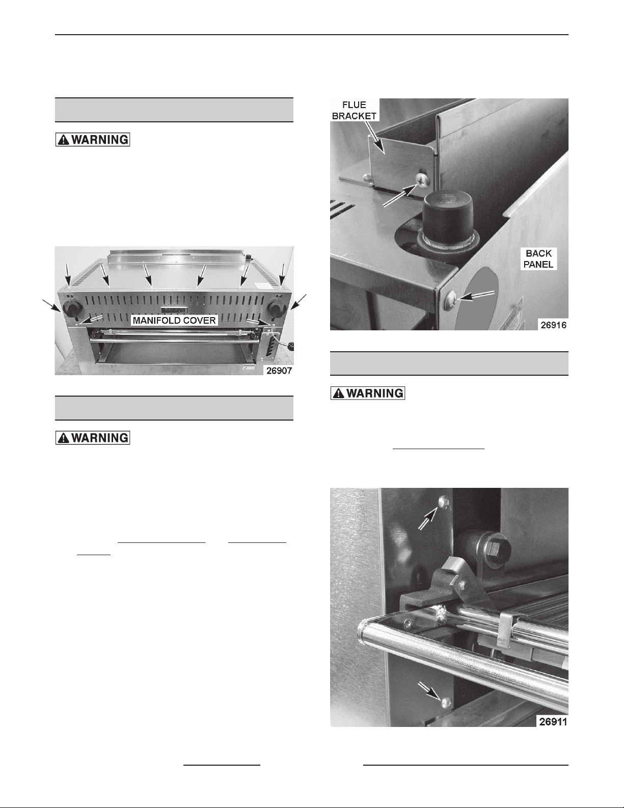
MANIFOLD COVER
Shut off the gas before servicing the
unit.
1. Loosen set screw and remove knobs from control
valves.
2. Remove screws that secure manifold cover and
remove the cover.
3. Reverse procedure to install.
Fig. 1
TOP PANEL ASSEMBLY
Shut off the gas before servicing the
unit.
NOTE: When viewed from the top, there are (5) flue
bracket mounting screws that secure the bracket and
the insulation pan (underneath) to the top panel only.
When removing the top panel assembly, these screws
can remain installed.
1. Remove
PANEL.
2. Remove the remaining screws securing Top
Panel Assembly to each side of the flue and back
panel.
3. Lift the Top Panel Assembly off broiler.
4. Reverse procedure to install.
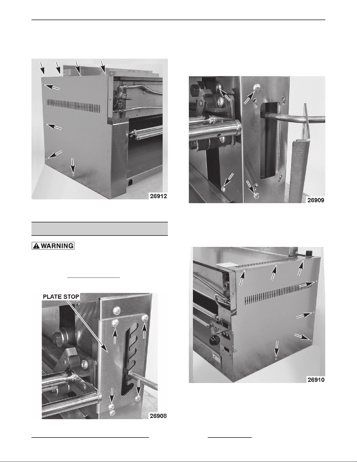
LEFT SIDE PANEL and RIGHT SIDE
Fig. 2
LEFT SIDE PANEL
Shut off the gas before servicing the
unit.
1. Remove crumb tray.
2. Remove
3. Position the rack assembly to access panel
screws in the broiler opening area.
MANIFOLD COVER.
F45530 (0814) Page 4 of 17
Fig. 3
Page 5
SALAMANDER BROILERS RADIANT AND INFRARED - REMOVAL AND REPLACEMENT OF PARTS
4. Remove screws securing left side panel. Slide
panel toward the front of broiler until panel clears
front mounting area then remove the panel.
Fig. 4
5. Reverse procedure to install.
RIGHT SIDE PANEL
Shut off the gas before servicing the
unit.
4. Pull knob off the handle on rack positioning
bracket then remove plate stop.
5. Position the rack assembly to access panel
screws in the broiler opening area. Remove
screws from this area and the front of panel.
Fig. 6
6. Remove screws securing right side panel to
broiler. Slide panel toward the front of broiler until
panel clears front mounting area then remove the
panel.
1. Remove crumb tray.
2. Remove
3. Remove screws securing plate stop to broiler.
MANIFOLD COVER.
Fig. 5
Fig. 7
7. Reverse procedure to install.
Page 5 of 17 F45530 (0814)
Page 6
SALAMANDER BROILERS RADIANT AND INFRARED - REMOVAL AND REPLACEMENT OF PARTS
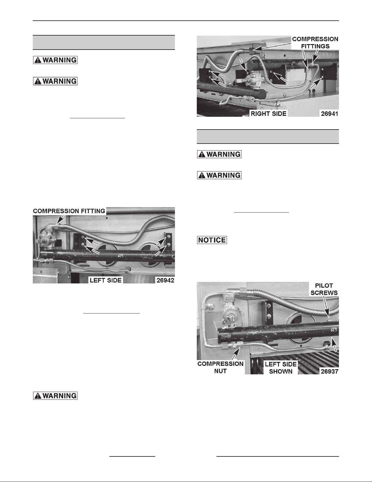
CONTROL VALVES (36RB/C36RB)
Shut off the gas before servicing the
unit.
All gas joints disturbed during
servicing must be checked for leaks. Check with a
soap and water solution (bubbles). Do not use an open
flame.
1. Remove
2. Left Valve:
A. Disconnect compression fitting from top of
B. Remove screws securing manifold to
C. Note orientation of elbow on valve then
D. Remove valve from manifold.
MANIFOLD COVER.
valve.
broiler.
remove the elbow. Retain for use on
replacement valve.
Fig. 8
Fig. 9
PILOT (36RB/C36RB)
Shut off the gas before servicing the
unit.
All gas joints disturbed during
servicing must be checked for leaks. Check with a
soap and water solution (bubbles). Do not use an open
flame.
1. Remove
2. Disconnect compression nut from straight pilot
valve fitting.
from the straight pilot valve fitting, support the fitting
to prevent damage to pilot flexible tubing.
3. Remove screws securing pilot and bracket to the
broiler.
MANIFOLD COVER.
When disconnecting compression nut
3. Right Valve:
A. Remove
B. Disconnect compression fittings from right
side manifold.
C. Remove screws securing right front
manifold and right side manifold to broiler.
D. Note orientation of control valve then
remove it from the each of the manifolds.
NOTE: When installing, ensure control valve is
perpendicular to the right front manifold.
sealant that is suitable for use with propane gases.
4. Reverse procedure to install.
5. Check for proper operation.
F45530 (0814) Page 6 of 17
RIGHT SIDE PANEL.
4. Remove pilot through broiler cooking area.
Clean pipe threads and apply thread
Fig. 10
Page 7

SALAMANDER BROILERS RADIANT AND INFRARED - REMOVAL AND REPLACEMENT OF PARTS
2. Pull rack assembly out and access the rack stops
on the left and right sides of the rack assembly.
Allow enough clearance at the rear of rack
assembly to rotate the rack stops to a horizontal
position. If the rack assembly is pulled all the way
out the rack assembly will engage the rack stops
and prevent removal.
Fig. 11
5. Remove pilot from bracket.
6. To install replacement pilot:
A. Insert mounting groove on the pilot into the
mounting slot on the pilot bracket.
B. Re-crimp the pilot bracket to secure the
pilot.
C. Slide compression nut and sleeve (ferrule)
over one end of the replacement flexible
tubing for the pilot. Insert flexible tubing into
the pilot and tighten compression nut to
secure.
3. Grasp the rack assembly near the broiler, rotate
both the rack stops horizontally and pull the rack
assembly out enough for the rack assembly
frame to clear the rack stops.
Fig. 12
D. Bend flexible tubing to match original pilot
configuration. Route flexible tubing through
opening in broiler frame and install pilot
bracket to broiler.
NOTE: When installing, ensure the pilot is close to the
ignition ports on the bottom of burner for proper burner
lighting. If necessary, bend the bracket so that the pilot
remains in contact with the burner casting.
E. Slide compression nut and sleeve over the
opposite end of flexible tubing. Insert flexible
tubing into the straight pilot valve on broiler
and tighten compression nut to secure.
7. Check for proper operation.
RADIANT BURNER (36RB/C36RB)
Shut off the gas before servicing the
unit.
1. Adjust rack assembly to the center position.
Fig. 13
4. Grasp the rack assembly and drip tray on each
side to support the tray and remove from broiler.
Page 7 of 17 F45530 (0814)
Page 8

SALAMANDER BROILERS RADIANT AND INFRARED - REMOVAL AND REPLACEMENT OF PARTS
CONTROL VALVES (36IRB/C36IRB)
Shut off the gas before servicing the
unit.
All gas joints disturbed during
servicing must be checked for leaks. Check with a
soap and water solution (bubbles). Do not use an open
flame.
Fig. 14
5. From inside broiler cooking area, remove cotter
pin securing burner to broiler frame. Retain pin
for reuse.
Fig. 15
6. Lift burner from the rear and slide it off the gas
orifice to remove from broiler.
1. Remove
2. Left Valve:
A. Remove screws securing valve mounting
B. Disconnect compression fitting from the
C. Note orientation of elbows on valve then
MANIFOLD COVER.
bracket to broiler
elbows at the top and bottom of valve.
remove the elbows. Retain for use on
replacement valve.
3. Right Valve:
Fig. 16
7. Reverse procedure to install.
8. Perform
ADJUSTMENT (36RB/C36RB).
F45530 (0814) Page 8 of 17
RADIANT BURNER AIR SHUTTER
Fig. 17
A. Remove screws securing valve stem
assembly to valve.
Page 9

SALAMANDER BROILERS RADIANT AND INFRARED - REMOVAL AND REPLACEMENT OF PARTS
Clean pipe threads and apply thread
sealant that is suitable for use with propane gases.
NOTE: When installing: Right valve - apply a light coat
of valve grease under the stop on the valve stem (see
LUBRICATION). Left & Right Valves - Ensure control
valves are aligned and centered in the manifold cover
opening. The valves must be perpendicular to the
manifold.
4. Reverse procedure to install.
5. Check for proper operation.
PILOT (36IRB/C36IRB)
Shut off the gas before servicing the
unit.
All gas joints disturbed during
Fig. 18
B. Note location of spring and remove it if still
inside valve body.
servicing must be checked for leaks. Check with a
soap and water solution (bubbles). Do not use an open
flame.
1. Remove
PANEL if replacing left pilot and RIGHT SIDE
PANEL if replacing right pilot.
MANIFOLD COVER, LEFT SIDE
Fig. 19
C. Disconnect compression fitting from the
elbow at the bottom of valve.
D. Remove valve from manifold.
E. Note orientation of elbow on valve then
remove the elbow. Retain for use on
replacement valve.
2. From inside the broiler cooking area, disconnect
compression fitting from the pilot.
When disconnecting compression fitting
for the pilot, support bracket to prevent bending.
Fig. 20
3. Remove screws securing pilot and bracket to the
broiler.
Page 9 of 17 F45530 (0814)
Page 10

SALAMANDER BROILERS RADIANT AND INFRARED - REMOVAL AND REPLACEMENT OF PARTS
Fig. 23
4. Right side:
Fig. 21
4. Remove screws securing pilot to the bracket.
Fig. 22
5. Reverse procedure to install and check for proper
operation.
INFRARED BURNER (36IRB/
C36IRB)
Shut off the gas before servicing the
unit.
A. Disconnect gas supply at broiler.
B. Remove screws securing manifold to
broiler.
Fig. 24
C. Lower the manifold to access burner
mounting bracket screws.
D. Remove screws securing burner mounting
bracket to broiler frame.
All gas joints disturbed during
servicing must be checked for leaks. Check with a
soap and water solution (bubbles). Do not use an open
flame.
1. Remove
PANEL and RIGHT SIDE PANEL.
2. Remove TOP PANEL ASSEMBLY.
3. Left side:
A. Remove screws securing burner mounting
F45530 (0814) Page 10 of 17
MANIFOLD COVER, LEFT SIDE
bracket to broiler frame.
Fig. 25
E. Disconnect compression nut from elbow
orifice fitting to access the right side orifice
bracket mounting screw.
F. Remove screws securing orifice bracket to
broiler frame.
Page 11

SALAMANDER BROILERS RADIANT AND INFRARED - REMOVAL AND REPLACEMENT OF PARTS
Fig. 26
5. From inside the broiler cooking area, remove
screws on the of bottom right side of the burner.
The screws secure the burner mounting bracket
to the burner.
Fig. 28
7. Slide burner to the right (manifold side) until it
clears the burner opening in broiler frame on the
left. Lift burner to remove it from broiler.
Fig. 27
6. Lift right side burner mounting bracket from
burner and broiler frame.
8. Remove screws securing the left burner
mounting bracket to burner.
Fig. 29
9. Reverse procedure to install replacement burner.
NOTE: When installing, remove the left side orifice
bracket from the broiler for additional burner clearance
as necessary.
10. Check for proper operation.
Page 11 of 17 F45530 (0814)
Page 12

SALAMANDER BROILERS RADIANT AND INFRARED - REMOVAL AND REPLACEMENT OF PARTS
GAS PRESSURE REGULATOR
Shut off the gas before servicing the
unit.
All gas joints disturbed during
servicing must be checked for leaks. Check with a
soap and water solution (bubbles). Do not use an open
flame.
Clean pipe threads and apply thread
sealant that is suitable for use with propane gases.
NOTE: Gas pressure regulator should be installed as
close to the broiler inlet gas connection as possible.
1. Thread regulator onto pipe hand tight with arrow
pointing in direction of gas flow to the broiler.
4. Adjust regulator as outlined in
ADJUSTMENT.
REGULATOR
RACK SPRINGS
NOTE: Springs should be replaced in pairs for proper
operation of the rack lift assembly.
1. Remove crumb tray to access tension
adjustment nuts from the front of broiler.
2. Raise the rack lift assembly to its highest position
on stop plate to relieve spring tension.
3. Loosen nuts to remove any remaining tension on
springs.
4. Access the bottom of broiler and remove springs
from the lower arm casting and eye bolt.
Fig. 30
2. Tighten regulator securely in horizontal position
with the regulator adjustment upward as
described on regulator.
NOTE: Regulator will not function properly without
adjustment screw pointing upward.
3. Connect main gas supply line to gas pressure
regulator inlet.
Fig. 31
Fig. 32
5. Reverse procedure to install.
6. Perform
ADJUSTMENT.
RACK SPRING TENSION
F45530 (0814) Page 12 of 17
Page 13

SALAMANDER BROILERS RADIANT AND INFRARED - SERVICE PROCEDURES AND ADJUSTMENTS
SERVICE PROCEDURES AND ADJUSTMENTS
PILOT FLAME HEIGHT
1. Locate the pilot adjustment screws below the
burner control knobs (one on each side) on the
front of broiler. It is not necessary to remove the
manifold cover as adjustment access holes are
provided in the panel.
port. A white-blue flame is a result of excessive
primary air.
NOTE: The factory default air shutter positions are
half open natural; full open propane.
Fig. 34
INFRARED BURNER (36IRB/
C36IRB)
Fig. 33
2. Locate the pilots at the top of the broiler heating
area.
3. Monitor the pilots flame and burner lighting. Pilot
is in adjustment when it will stay on continually
and lights the burners without delayed ignition.
4. If adjustment is necessary, rotate the screw
clockwise to decrease and counterclockwise to
increase flame height.
RADIANT BURNER AIR SHUTTER
ADJUSTMENT (36RB/C36RB)
The efficiency of the burner depends on a delicate
balance between the air supply and volume of gas.
Whenever this balance is disturbed, poor operating
characteristics and excessive gas consumption may
occur. An air shutter on the front of the burner controls
the gas mixer balance. A yellow streaming flame on
the burner is an indication of insufficient primary air.
To correct this condition, loosen the shutter screw and
rotate the air shutter open until the flame begins to lift
from the burner, then close the shutter slightly and
tighten the shutter screw. A proper flame should be
blue in color, well-defined and seated on the burner
Adjustment
The only adjustment for the Infared burner is the gas
manifold pressure. Verify the pressure is set correctly
as outlined under
Flame Appearance
When the Infared burner first lights you should see a
small rolling blue flame, which will clear up after the
burner warms. Once warm, a low profile orange flame
is the best description of the Infared burner flame. In
some cases, if the burner is operating correctly, you
may not be able to see the actual flame. Instead you
will see the glow of the ceramic bricks in the burner.
REGULATOR ADJUSTMENT.
REGULATOR ADJUSTMENT
Shut off the gas before servicing the
unit.
NOTE: Regulators come preset, but should be
checked anytime one is installed. Before adjusting
regulator, check incoming gas line pressure. Incoming
pressure must be 6-14" W.C. for natural gas and
11-14" W.C. for propane gas. If incoming pressure is
not correct, have the gas source checked and
adjusted as necessary. Make sure the regulator is
mounted in the horizontal position with the arrow
pointing in the direction of gas flow. See
GAS
Page 13 of 17 F45530 (0814)
Page 14

SALAMANDER BROILERS RADIANT AND INFRARED - SERVICE PROCEDURES AND ADJUSTMENTS
PRESSURE REGULATOR under REMOVAL AND
REPLACEMENT OF PARTS.
See unit data plate, under crumb tray, for manifold
pressure setting information. Clean vent cap before
adjusting.
Fig. 36
B. Insert a flat edge screwdriver through the
top of the regulator. While watching the
manometer, turn the adjusting screw
clockwise to increase pressure and
counterclockwise to decrease pressure until
Fig. 35
1. Connect manometer to measure gas manifold
pressure.
A. 36RB/C36RB - Remove
COVER to access pressure tap on the
manifolds.
MANIFOLD
the proper gas pressure is achieved. See
data plate under crumb tray.
C. Install the regulator closing nut.
D. Turn gas supply off.
E. Remove manometer from pressure tap
location. If tee was installed, remove tee.
B. 36IRB/C36IRB - Install a tee with hose barb
connection on the outlet side of the
regulator. See
opposite end of the tee to broiler incoming
gas supply.
2. Turn gas supply on and light both pilots.
3. Open both valves to the full on position and check
manometer reading. The reading should be 5"
W.C. for natural gas and 10" W.C. for propane
gas. Tolerance is ±0.3" W.C.
4. If manifold pressure is not correct, adjust the
regulator as follows.
A. Remove the regulator closing nut.
TOOLS. Connect the
Clean pipe threads and apply thread
sealant that is suitable for use with propane gases.
F. Apply thread sealant to pipe threads and re-
install.
GAS ORIFICE CHECK
The gas orifice is mounted at the gas and air inlet for
the burner. If burner operation seems poor and other
systems have been checked, access the burner and
inspect:
• Gas orifice alignment - orifice should be centered
in the venturi opening and perpendicular to the
burner.
• Check gas orifice for blockage or damage. If dirty,
clean with air or water only.
• Verify gas orifice is correct for the altitude.
F45530 (0814) Page 14 of 17
Page 15

SALAMANDER BROILERS RADIANT AND INFRARED - SERVICE PROCEDURES AND ADJUSTMENTS
3. Check for proper operation.
Fig. 37
Fig. 38
CONTROL VALVES
Inspect the control valve for smooth rotation,
noticeable wear and any possible damage. The
burner flame should increase smoothly as the valve is
opened (highest setting) and decrease smoothly as
the valve is being closed. When inspecting valves,
always apply a light amount of valve grease at the
base of the valve stem. See
grease does improve rotation of the valve, or damage
is found, replace the control valve as outlined under
CONTROL VALVES (36RB/C36RB) or CONTROL
VALVES (36IRB/C36IRB).
LUBRICATION. If valve
Fig. 39
RACK SPRING TENSION
ADJUSTMENT
1. Access the springs on the bottom of broiler.
2. Tighten nut to adjust rack spring tension. Adjust
both springs equally so there is approximately
3/4" of thread above the nut. If additional rack
spring tension is required, tighten each nut an
additional 2-3 turns.
Page 15 of 17 F45530 (0814)
Page 16

SALAMANDER BROILERS RADIANT AND INFRARED - TROUBLESHOOTING
TROUBLESHOOTING
GENERAL (ALL MODELS)
GENERAL
SYMPTOM POSSIBLE CAUSE
1. Incorrect gas type.
Pilot does not remain lit.
Slow to heat or not hot enough.
Broiler temperature too hot.
SYMPTOM POSSIBLE CAUSE
2. Incorrect gas pressure.
3. Pilot burner not adjusted properly.
4. Pilot burner blocked or Incorrect pilot orifice.
1. Incorrect gas type.
2. Low gas pressure.
3. Regulator adjustment or malfunction.
4. Control valve malfunction.
1. Incorrect gas type.
2. Regulator adjustment or malfunction due to high gas
pressure.
3. Control valve malfunction.
RADIANT BURNER (36RB/C36RB)
RADIANT BURNER
1. Orifice incorrect size or dirty.
2. Air shutter not adjusted correctly or dirty.
Flame too yellow.
Low burner flame (all burners).
Low burner flame (individual burner). 1. Air mixture incorrect.
Flame floats on burner.
3. Incorrect gas pressure.
4. Incorrect gas type.
5. Orifice not aligned properely in venturi.
6. Appliance not venting properly.
1. Regulator adjustment or low gas pressure.
2. Incorrect gas type.
1. Inadequate air supply.
2. Restricted exhaust flue.
INFRARED BURNER (36IRB/C36IRB)
F45530 (0814) Page 16 of 17
Page 17

SALAMANDER BROILERS RADIANT AND INFRARED - TROUBLESHOOTING
INFRARED BURNER
SYMPTOM POSSIBLE CAUSE
1. Orifice incorrect size or dirty.
2. Incorrect gas pressure.
3. Incorrect gas type.
Flame not orange.
Burner not lighting properly or incorrect burner flame
appearance due to clogged ports.
4. Orifice not aligned properely in venturi.
5. Appliance not venting properly.
6. Clogged burner ports.
7. Burner malfunction.
1. Broiler with Infrared burner is mounted too close to
a fryer or charbroiler and the grease laden air is
causing burner ports to clog. If burner ports are
found to be clogged, install a replacement burner.
NOTE: Grease laden air is detrimental to the life of
the Infrared burner. If a technician sees a broiler with
Infrared burner mounted in a location close to a fryer
or charbroiler, please recommend to the customer
to move the broiler away from the grease laden air
source to prolong the life of the Infrared burner.
Page 17 of 17 F45530 (0814)
 Loading...