

Page 1
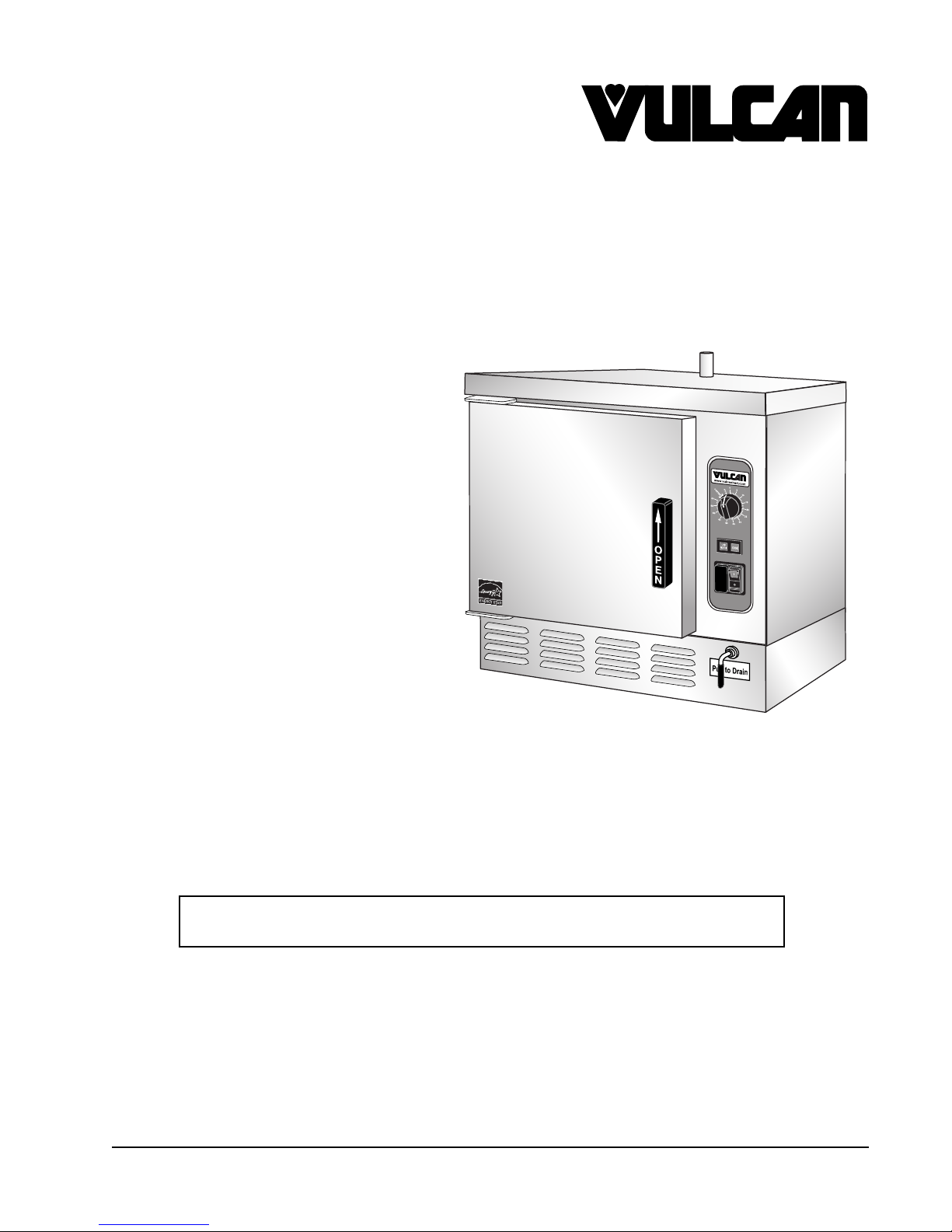
C24EO SERIES
STEAMER
MODEL ML
MANUAL FILL
INSTALLATION &
OPERATION MANUAL
C24EO3 ML-136006
C24EO5 ML-136007
AUTO-FILL TECHNOLOGY
C24EO3AF ML-152054
C24EO5AF ML-152055
For additional information on Vulcan or to locate an authorized parts
and service provider in your area, visit our website at www.vulcanequipment.com
VULCAN
DIVISION OF ITW FOOD EQUIPMENT GROUP, LLC
WWW.VULCANEQUIPMENT.COM
3600 NORTH POINT BLVD.
BALTIMORE, MD 21222
FORM F-37496 Rev. A (10-18)
Page 2

C24EO SERIES STEAMER
IMPORTANT FOR YOUR SAFETY
THIS MANUAL HAS BEEN PREPARED FOR PERSONNEL QUALIFIED TO
INSTALL THIS EQUIPMENT, WHO SHOULD PERFORM THE INITIAL FIELD
START-UP AND ADJUSTMENTS OF THE EQUIPMENT COVERED BY
THIS MANUAL.
WARNING
IMPROPER INSTALLATION, ADJUSTMENT, ALTERATION,
SERVICE OR MAINTENANCE CAN CAUSE PROPERTY
DAMAGE, INJURY OR DEATH. READ THE INSTALLATION,
OPERATING AND MAINTENANCE INSTRUCTIONS
THOROUGHLY BEFORE INSTALLING OR SERVICING
THIS EQUIPMENT.
IN THE EVENT OF A POWER FAILURE, DO NOT
ATTEMPT TO OPERATE THIS DEVICE.
© VULCAN, 2018
— 2 —
Page 3

C24EO SERIES STEAMER
TABLE OF CONTENTS
INSTALLATION, OPERATION AND CARE OF MODEL C24EO SERIES STEAMERS ....................5
GENERAL ....................................................................................................................................5
INSTALLATION ............................................................................................................................5
UNPACKING................................................................................................................................5
INSTALLATION CODES AND STANDARDS ..............................................................................5
LOCATION...................................................................................................................................6
LEVELING FEET .........................................................................................................................6
LEVELING ...................................................................................................................................6
ANCHORING STEAMER ............................................................................................................6
OPTIONAL ACCESSORIES ........................................................................................................6
ELECTRICAL CONNECTIONS ...................................................................................................7
ELECTRICAL DATA .....................................................................................................................8
SERVICE CONNECTIONS .........................................................................................................8
Water Connections (Manual Fill Units) ..................................................................................8
Water Connections (Auto-Fill Units) ......................................................................................8
Water Requirements ..............................................................................................................8
Drain Connection ...................................................................................................................8
VENT HOOD ...............................................................................................................................9
BEFORE FIRST USE ..................................................................................................................9
INSTALLATION STARTUP PROCEDURE ..................................................................................9
Calibration Procedure ..........................................................................................................10
OPERATION ....................................................................................................................................12
CONTROLS ...............................................................................................................................12
OPERATING THE STEAMER ...................................................................................................12
LOW WATER .............................................................................................................................13
SHUTDOWN .............................................................................................................................13
EXTENDED SHUTDOWN .........................................................................................................13
CLEANING ......................................................................................................................................14
COOKING COMPARTMENT DRAIN .........................................................................................14
COMPARTMENT .......................................................................................................................14
DOOR GASKET ........................................................................................................................14
LEAVE COMPARTMENT DOOR OPEN....................................................................................14
STAINLESS STEEL EQUIPMENT CARE AND CLEANING .................................................15
MAINTENANCE ..............................................................................................................................17
REMOVAL OF LIME SCALE DEPOSITS ...............................................................................17
DOOR GASKET ........................................................................................................................17
— 3 —
Page 4

C24EO SERIES STEAMER
COOKING HINTS ............................................................................................................................18
ACCEPTABLE PAN SIZES .....................................................................................................18
COOKING GUIDELINES ...........................................................................................................18
PREPARATION .........................................................................................................................18
Frozen Food Items ...............................................................................................................18
PRODUCTS TO BE COOKED IN SOLID PANS .......................................................................19
PRODUCTS TO BE COOKED IN PERFORATED PANS ..........................................................20
TROUBLESHOOTING ....................................................................................................................22
SERVICE AND PARTS INFORMATION ..........................................................................................23
— 4 —
Page 5

C24EO SERIES STEAMER
INSTALLATION, OPERATION AND CARE OF
MODEL C24EO SERIES STEAMERS
PLEASE KEEP THIS MANUAL FOR FUTURE USE
GENERAL
Vulcan convection steamers are produced
with quality workmanship and material. Proper
installation, usage and maintenance will result
in many years of satisfactory performance. It is
suggested that you thoroughly read this entire
manual and carefully follow all of the instructions
provided.
The C24EO3 Steamer is rated at 8.0 kW and
the C24EO5 Steamer is rated at 12.0 kW.
Model C24EO3 can accommodate three 2
deep (6.4 cm) steam pans. Model C24EO5
can accommodate fi ve 2
steam pans. The C24EO3 and C24EO5
electric convection steamers are designed for
cooking vegetables, eggs, and other foods,
in commercial kitchens. The steamer has a
0 to 60 minute timer. The steamers are designed
for installation on countertops or on optional
stands.
New to this product line are the C24EO3AF &
C24EO5AF Auto-Fill models. These models fi ll
the cavity with water automatically. The physical
dimensions, cooking instructions and electrical
specifi cations are the same as the standard
C24EO models.
1
/2" deep (6.4 cm)
1
/2"
INSTALLATION
Before installing, verify that the electrical supply
agrees with the specifi cations on the data plate
located on the front of the steamer in the lower
right hand corner. If the supply and equipment
requirements do not agree, do not proceed with
the installation. Contact your dealer or Vulcan
immediately.
The C24EO3 is shipped pre-wired for 208
V, 50 to 60 Hz, 3-phase. 240 V and single
phase operation require changes to the heater
connection 240 V, 50 to 60 Hz, 3-phase / 240
V, 50 to 60 Hz, 1-phase and 208 V, 50 to 60
Hz, 1-phase.
The C24EO5 is voltage specifi c. It is available
at 208 V, 50 to 60 Hz, 3-phase / 240 V, 50 to 60
Hz, 3-phase or 480 V, 50 to 60 Hz, 3-phase. It
can be fi eld converted to single phase.
UNPACKING
This steamer was inspected before leaving the
factory. The transportation company assumes full
responsibility for safe delivery upon acceptance
of the shipment. Immediately after unpacking,
check for possible shipping damage. If the
steamer is found to be damaged, save the
packaging material and contact the carrier within
15 days of delivery.
INSTALLATION CODES
AND STANDARDS
The steamer must be installed in accordance
with:
In the United States of America:
1. State and local codes.
2. National Electrical Code, ANSI/NFPA-70
(latest edition). Copies may be obtained from
The National Fire Protection Association,
Batterymarch Park, Quincy, MA 02269.
3. Vapor Removal from Cooking Equipment,
(NFPA-96, latest edition) available from
NFPA.
In Canada:
1. Local codes.
2. Canadian Electric Code, CSA C22.2 (latest
edition). Copies may be obtained from
The Canadian Standard Association, 5060
Spectrum Way, Suite 100, Mississauga,
Ontario, Canada L4W 5N6.
— 5 —
Page 6
C24EO SERIES STEAMER
LOCATION
The installation location must allow adequate
clearances for servicing and proper operation.
Minimum clearance for proper air circulation is
2" (5.1 cm) on the sides and 6" (15.2 cm) on
the back.
LEVELING FEET
This steamer is shipped with four 2" leveling
feet. Optional 4" leveling feet are available.
The 2" feet can be removed and the optional 4"
feet can be threaded into holes on the bottom
of the unit.
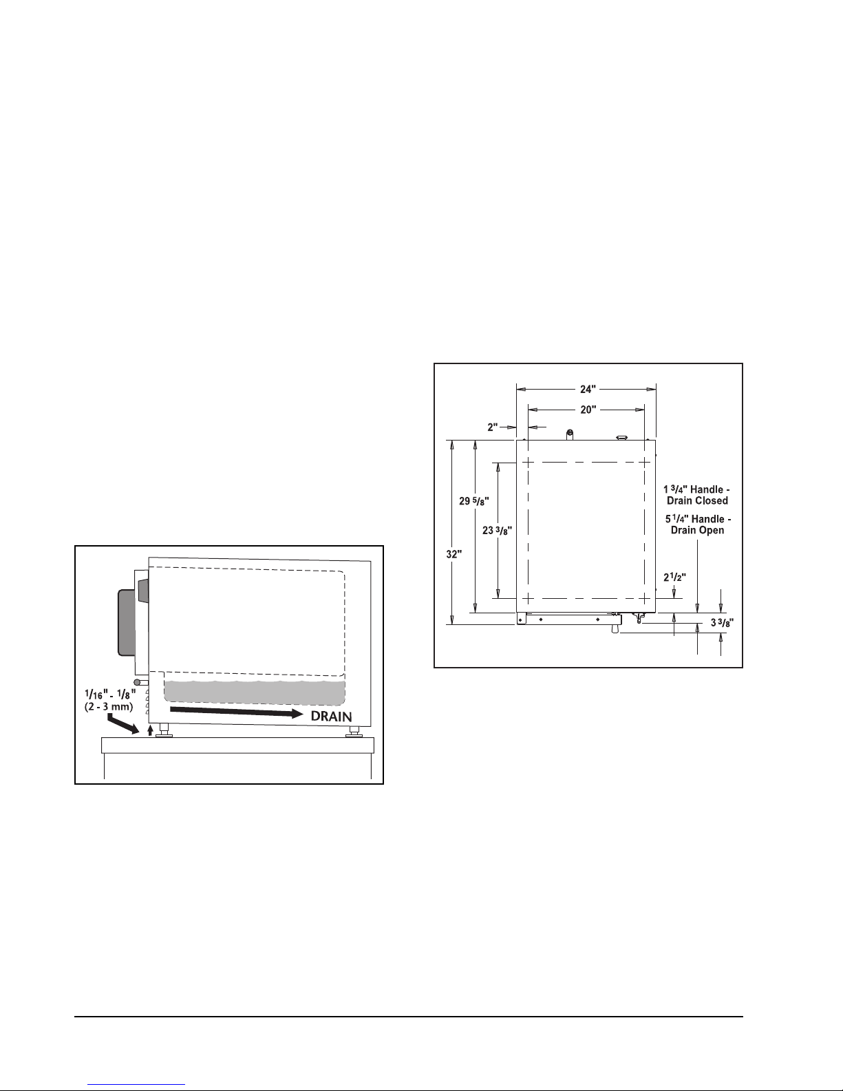
LEVELING
Position and level the unit using leveling feet.
Front of unit should be
the rear as indicated in Figure 1. Unit should be
level side to side.
1
/16" to 1/8" higher than
ANCHORING STEAMER
1. Place steamer in the desired location on
the countertop and mark four corners.
Remove the steamer and drill
indicated in Figure 2.
2. Apply a bead of RTV or other NSF approved
sealant around the bottom edge of the
steamer. If anchoring the steamer, this
bottom seal is necessary to meet NSF
requirements.
3. Set steamer on countertop and bolt down
securely with
3
/8" by 16" bolts (not supplied).
Screw length should be tabletop thickness
1
plus
/2" for proper thread engagement.
1
/2" holes as
Level the steamer front to back and side to side
by turning the adjustable feet.
Figure 1: Leveling Steamer
Figure 2: Anchoring Steamer
OPTIONAL ACCESSORIES
Optional accessories such as stands and
stacking kit will include directions for
assembly.
— 6 —
Page 7
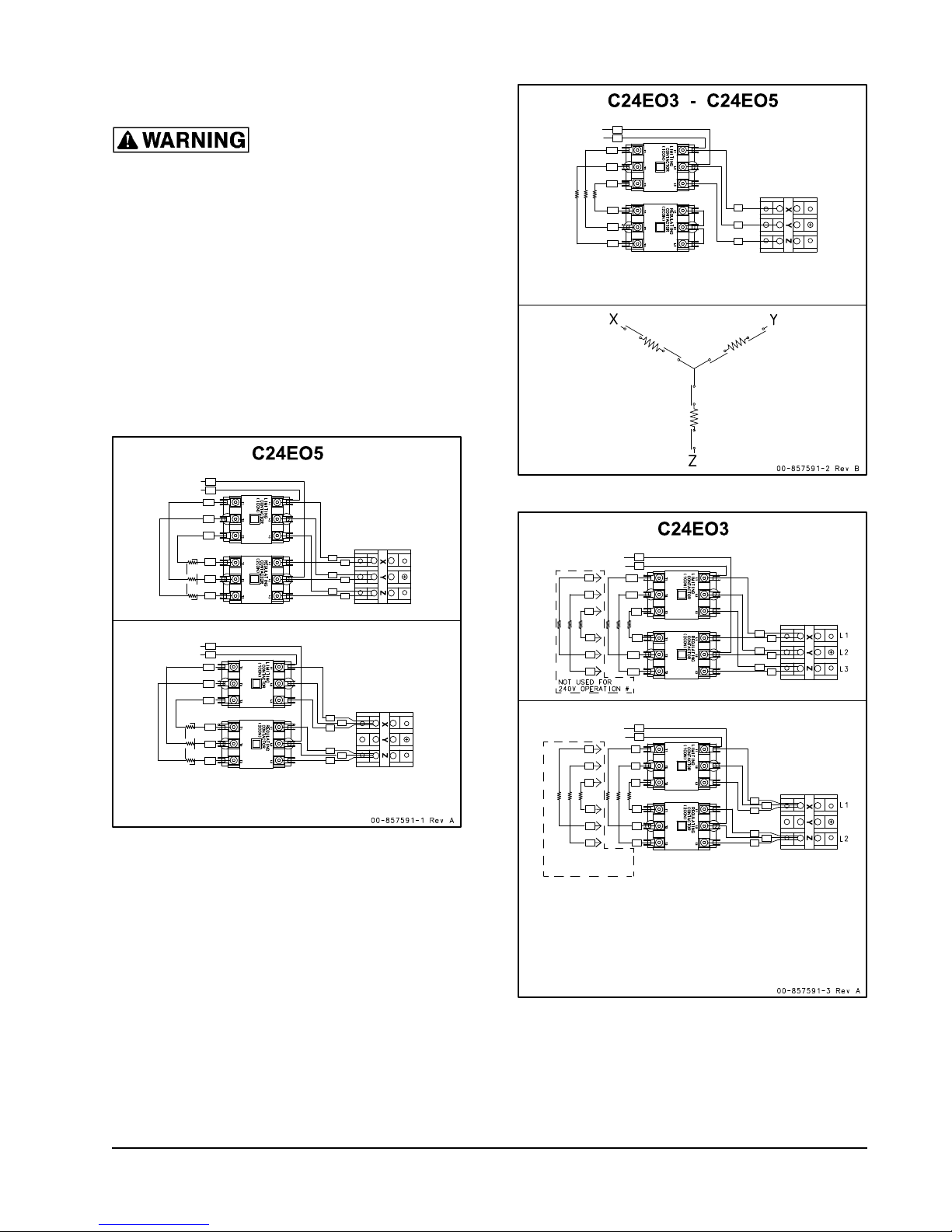
ELECTRICAL CONNECTIONS
To Control
Transformer
To Control
Transformer
3-S, 20
3-S, 20
1-S, 20
1-S, 20
21
2
21
22
23
2
2
2
22
2
23
2
rimary taps of Control Transformer must be connected
according to the appliance data plate voltage marking and
actual connected supply.
To Control
Transformer
3-S, 30
3-S, 1
3-S, 0
1C 1 T1
2C T2 2
1C 2 T2
2C T3 3
2C T1 1
1C 3 - T 3
21
22
23
rimary taps of Control Transformer must be connected
according to the appliance data plate voltage marking and
actual connected supply.
To Control
Transformer
To Control
Transformer
3-S, 2020
1-S, 2020
21
2
21
22
23
2
2
2
22
2
23
2
rimary taps of Control Transformer must be connected
according to the appliance data plate voltage marking and
actual connected supply.
For operation from a 20 supply, all elements are to
be connected as shown. For 20 supply, disconnect and
insulate element leads with range, reen and ed markers.
ot used for
20 operation
: Electrical and
grounding connections must comply
with the applicable portions of the
National Electrical Code and/or other
local electrical codes.
When making electrical connections, use copper
wire suitable for at least 200°F (90°C). The
steamer must be grounded. The wiring diagram
is located on the inside of the right panel.
Steamers are wired for 3-phase and can be
converted to 1-phase by relocating the jumper
wires on the terminal block as shown on the
wiring diagram.
C24EO SERIES STEAMER
— 7 —
Page 8

C24EO SERIES STEAMER
ELECTRICAL DATA
Model Volts KW Amp @
1PH
C24EO3 208 8 38.5 22.2
240 8 33.3 19.2
C24EO5 208 12 57.7 33.3
240 12 50.0 28.9
480 12 N/A 14.4
Amp @
3 PH
SERVICE CONNECTIONS
Water Connections (Manual Fill Units)
No water supply connections are required, as
the steamer is fi lled manually.
Water Connections (Auto-Fill Units)
Water Requirements
Proper water quality can improve the taste
of the food prepared in the steamer, reduce
liming in the steam generator and extend
equipment life. Water conditions vary from one
location to another. Presence of iron content,
amount of chloridation and dissolved gases could
aff ect the taste. Adding a carbon block fi lter to
the water inlet will improve taste.
Drain Connection
The C24EO can be confi gured to drain through
either the rear panel or through the bottom base
plate.
The unit is confi gured to be drained through the
rear panel from the factory. The unit is supplied
with a 12" length of
5
/8" ID hose. If this length is
insuffi cient, remove the hose and install a new
hose ordered to the desired length. The factory
5
/8" ID silicone hose part number is 557475. Hose
is sold by the foot.
NOTE: Auto-Fill steamers will refi ll automatically
if the water level is low.
Connect the cold water supply line to the 3/4"
(19 mm) (male hose thread) inlet.
A manual shutoff valve must be provided in a
convenient location near the steamer.
The incoming water pressure must be 20 - 60
psig.
Cold Water
Connection
See Figure 3.
Figure 3: Rear Panel Drain Connection
(Viewed with right side panel removed)
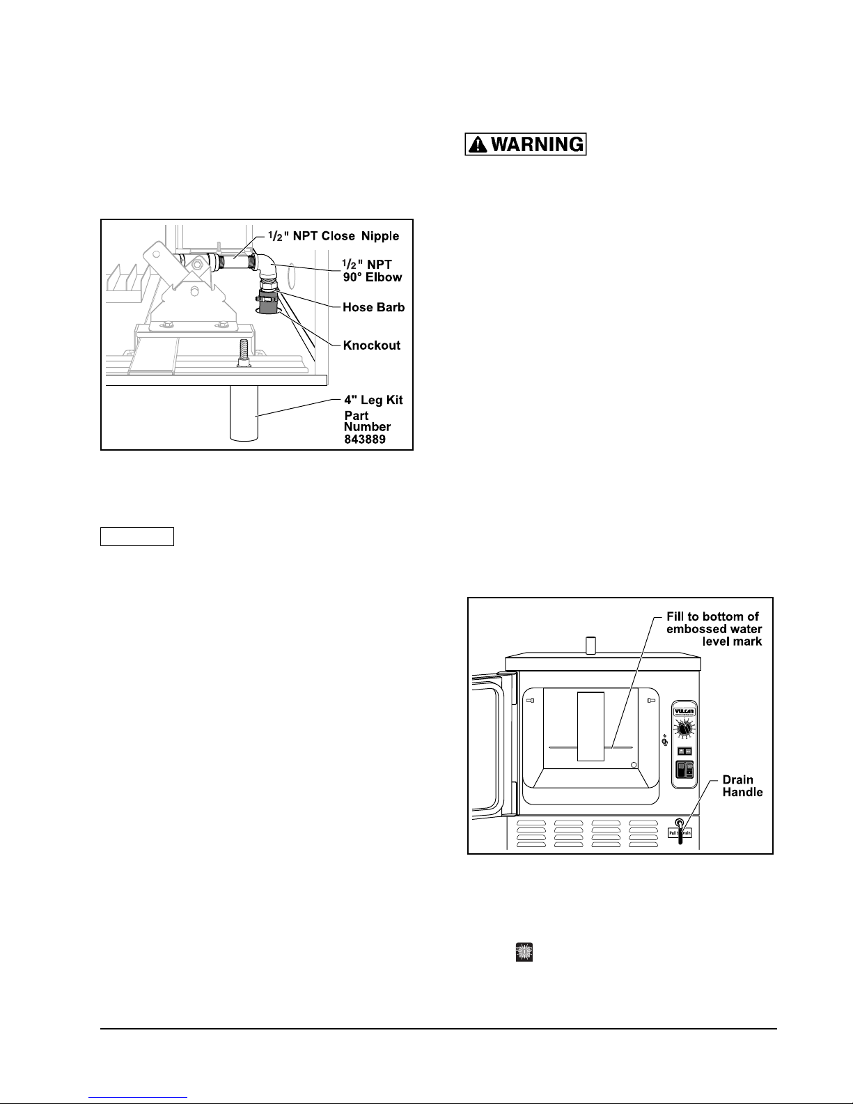
To fi eld confi gure the drain through the bottom
base plate, the 4" leg kit (part number 843889) is
required. Also required are a
nipple (1
1
/8" long) and a 1/2" NPT 90° elbow, which
1
/2" NPT close pipe
are available through local home improvement
or plumbing supply houses.
1. Remove right side panel.
2. Remove hose barb from drain.
3. Remove knockout from base plate.
— 8 —
Page 9
C24EO SERIES STEAMER
4. Install the 1/2" NPT close nipple (11/8" long)
into drain.
5. Install 1/2" NPT 90° elbow onto pipe nipple.
6. Re-use hose barb.
7. Install hose barb into elbow with clamp, cut
to desired length or route to drain.
Figure 4: Bottom Panel Drain Connection
(Viewed with right side panel removed)
NOTICE Do not connect steamer drain solidly
to any drain piping. The steamer drain must
vent to the atmosphere to avoid creating a back
pressure and possible back siphoning into the
compartment.
INSTALLATION STARTUP
PROCEDURE
: The steamer and its
parts are hot. Use care when operating,
cleaning or servicing the steamer. The
cooking compartment contains live steam
and hot water. Stay clear when opening
the door.
Once the steamer is installed, thoroughly test
the steamer before operation.
1. Check that the proper electrical connections
have been made.
NOTE: On Auto-Fill model, verify that the water
supply line has been connected properly.
The incoming water pressure to the
steamer needs to be 20 - 60 psig.
2. Close the drain valve by pushing the Drain
Handle in, located in the lower right hand
corner. On manual fi ll units, open the door and
pour water into the cooking compartment up
to the water level mark (the water level mark
is visible on the back wall of the steamer).
Do not overfi ll.
VENT HOOD
Local codes may require the steamer to be
located under an exhaust hood. Information on
the construction and installation of ventilating
hoods may be obtained from Vapor Removal
from Cooking Equipment, NFPA Standard No.
96 (latest edition).
BEFORE FIRST USE
Thoroughly clean the steamer before using for
the fi rst time. See the CLEANING section in
this manual.
— 9 —
Figure 5: Water Level Mark (Manual Fill)
3. Rotate the Timer to CONTINUOUS position.
Fully depress the Power Switch to the
ON
position. The Power Switch will turn
amber, indicating the unit is turned on.
Page 10

C24EO SERIES STEAMER
4. With the door open, press in on the door
switch (small rod), located above the door
latch. The COOK light will come on. Release
the door switch and the COOK light will turn
off .
5. Close the compartment door and wait
approximately 10 minutes for unit to preheat.
6. Rotate the Timer to 5 minutes. The Timer
will not start counting down until the cavity
has reached preheat temperature.
7. When the timer returns to 0, a buzzer will
sound signaling the end of the cooking cycle.
To silence the buzzer, turn the Timer dial to
the OFF position.
8. To turn the steamer off :
a. Depress the Power Switch to
the OFF
b. Allow the steamer
position.
to cool.
c. Open the drain valve and drain the water
from the steamer.
d. Open the compartment door to allow the
inside to dry out.
ELEVATION (FT) DIGITAL THER-
MOMETER - °F (C)
Sea Level 210 (99)
1,000 208 (98)
2,000 206 (97)
3,000 204 (96)
4,000 202 (94)
5,000 200 (93)
6,000 198 (93)
7,000 196 (91)
8,000 195 (90)
9,000 or above 194 (90)
1. Remove right side panel.
2. Place a temperature probe approximately
one inch down in the center of steam vent
pipe.
3. Turn steamer on by selecting CONTINUOUS
mode.
4. Using the table above, fi nd the corresponding
temperature for the elevation and set the
Temperature Control.
CALIBRATION PROCEDURE
The right hand side panel must be removed
to access the temperature controller. To
achieve optimum steamer operation, rotate the
Temperature Control to the temperature that
corresponds to the elevation that it is located at.
NOTE: The steamer is preset at the factory to
sea level.
A handheld digital thermometer and thermocouple
are required.
NOTE: If temperature setting is too high, the
boiling action will be excessive and
cause water droplets to exit the steam
vent pipe resulting in high water usage.
Figure 6: Temperature Control
— 10 —
Page 11

C24EO SERIES STEAMER
NOTE: Temperature Control is configured
by vendor to Fahrenheit and cannot
be changed to Celsius. The display
indicates set point temperature only.
a. Wait 3 seconds after releasing the knob
for the selection to be saved in memory.
Display will blink momentarily to indicate
temperature is saved.
b. Allow temperature to stabilize by
completing two heating cycles with door
closed.
NOTE: Temperature display on control is for
reference only. When calibrating, use
the recorded temperature from meter.
5. Record temperature reading from meter
when load light goes out.
6. Compare recorded temperature to the
temperature from table.
a. If recorded temperature is correct, no
adjustment is necessary.
b. If recorded temperature is not correct,
adjust temperature setting and re-check
the temperature reading with meter.
NOTE: If unit cannot be calibrated call your
Authorized Vulcan Servicer.
7. If correct temperature reading is not attained
after 3 attempts, call your Authorized Vulcan
Servicer.
— 11 —
Page 12
C24EO SERIES STEAMER
OPERATION
CONTROLS
: The steamer and its
parts are hot. Use care when operating,
cleaning or servicing the steamer. The
cooking compartment contains live steam
and hot water. Stay clear when opening
the door.
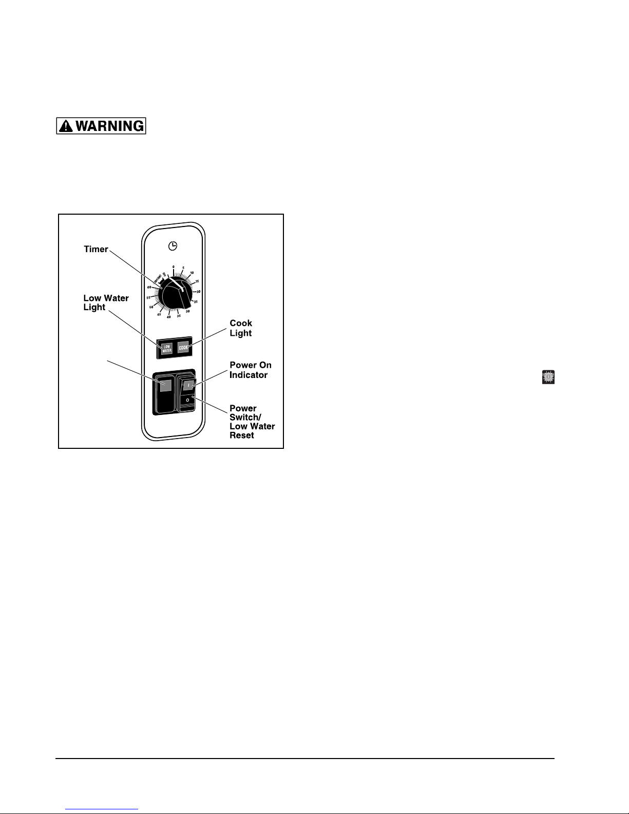
TIMER
Overfill
Light
OVERFILL
OPERATING THE STEAMER
1. Push the drain lever in to close the drain
valve.
2. Open the door and pour water into the
cooking compartment up to the water level
mark. The water level mark is visible on the
back wall of the steamer. Unit capacity is 3
gallons. Do not overfi ll.
3. Close door.
NOTE: On Auto-Fill model, the unit will
automatically fi ll with water once the start
button is pressed. The steamer will fi ll
until water reaches the water level probe
located inside the cavity. If the door is
closed, the steamer will heat the water
during the initial fi ll cycle.
4. Verify Timer is in the OFF position.
5. Fully depress Power Switch to ON
position. Power light in switch will illuminate
amber.
Figure 7: Controls
Power Switch/Low Water Reset: Turns
unit OFF/ON/RESETS LOW WATER LIGHT/
ALARM.
Low Water Light: When lit, indicates additional
water is required.
Timer: Selects the desired cooking time or the
CONTINUOUS position.
COOK Light: When lit, indicates the timer is
set and door is closed.
OVERFILL Light: (Auto-Fill model only): When
lit, indicates a problem with the Auto-Fill function
(an audible alarm will sound in the event of an
overfi ll condition).
6. Set timer to 5 minutes. In approximately 15
minutes unit will be preheated and ready to
cook.
7. Set timer to desired time (0 to 60 minutes)
or to CONTINUOUS position.
8. At the end of the timed cycle an audible
alarm will sound.
9. The unit returns to the idle temperature.
NOTE: Timer will not function until preheat has
been completed.
— 12 —
Page 13

C24EO SERIES STEAMER
LOW WATER
1. When the Low Water light is illuminated
the unit needs to be refi lled with water. An
audible alarm will sound.
2. Fully depress Power Switch to OFF
position.
3. Refi ll unit with water.
4. Close door.
5. Fully depress Power Switch to ON
position to cancel Low Water alarm.
6. Timer will resume when steamer reaches
cooking temperature.
NOTE: Refi ll the unit when not in use or during
slow times to avoid running out of water.
Running out of water during a cooking
cycle will lengthen cook time. This
comment does not apply to the Auto-Fill
model. If the low water light is on, refer
to the troubleshooting section.
SHUTDOWN
1. Rotate Timer to OFF position.
2. Fully depress Power Switch to OFF
position.
3. Allow steamer to cool.
4. Open the drain valve and drain the water
from steamer.
5. Open the compartment door to allow the
inside to dry.
6. Follow cleaning instructions in this manual.
EXTENDED SHUTDOWN
1. Fully depress Power Switch to OFF
position.
2. Clean the interior and exterior of unit.
3. Leave door open.
4. Disconnect power.
— 13 —
Page 14
C24EO SERIES STEAMER
CLEANING
COOKING COMPARTMENT DRAIN
Remove any particles or debris that may be
blocking the drain. Make a solution of warm
water with non-chloride detergent and pour
1
/2 gallon (1.9 liters) of it down the compartment
drain. Rinse by pouring
hot water down the compartment drain.
1
/2 gallon (1.9 liters) of
Thoroughly clean the exposed surfaces (sides,
front, door and top) with a damp cloth and polish
with a clean cloth daily. To remove discolorations,
use a nonabrasive cleaner.
DOOR GASKET
Clean the gasket sealing surface of the
compartment door daily to remove food acids for
maximum gasket life. Do not use any solvents or
sharp instruments. Wash with a cloth moistened
in a solution of mild detergent and warm water.
Rinse with a fresh cloth moistened with warm
water to remove all traces of detergent.
Wipe dry with a clean cloth. Never apply food
oils or petroleum lubricants directly to the door
gasket. Petroleum-based solvents and lubricants
will reduce gasket life.
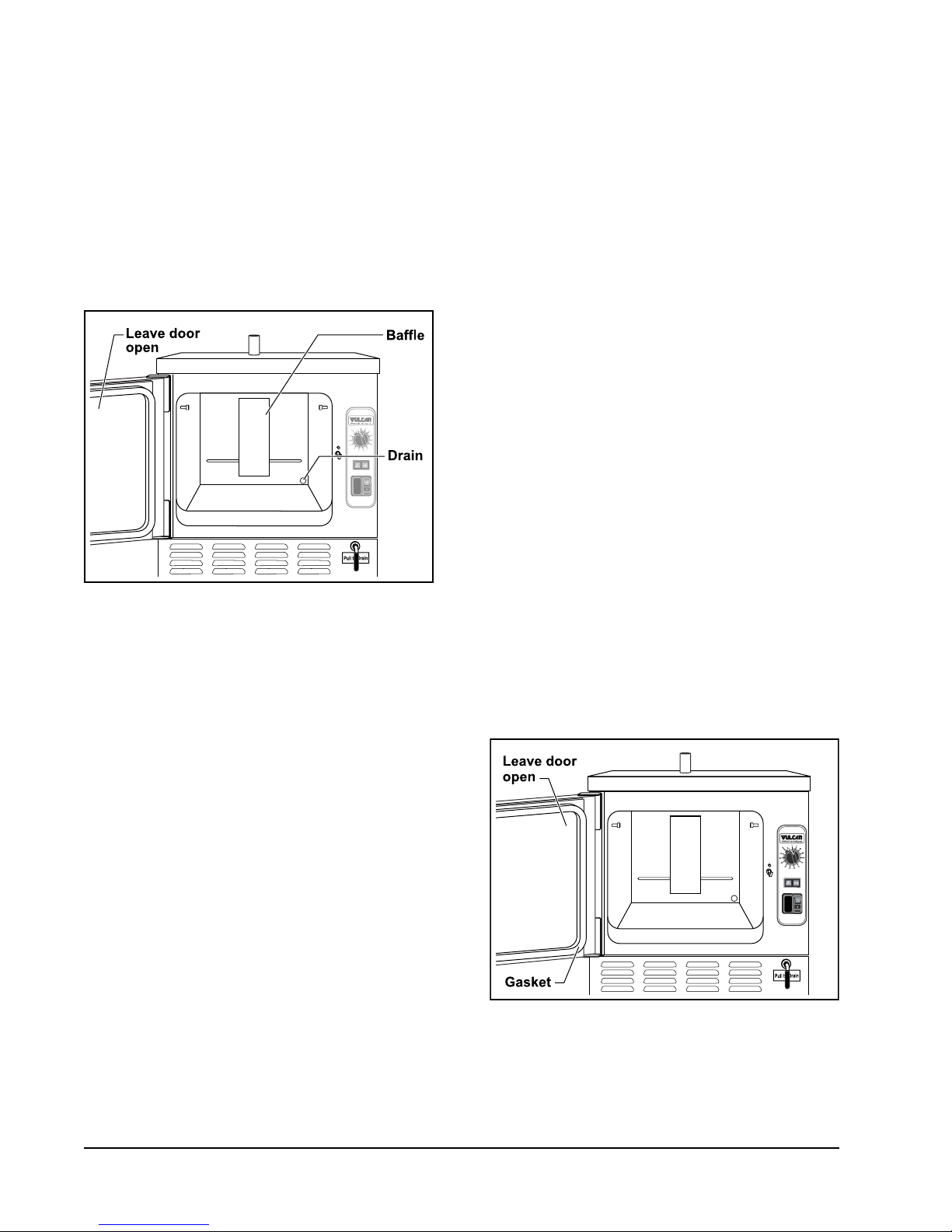
LEAVE COMPARTMENT DOOR OPEN
Figure 8: Oven Cavity
COMPARTMENT
The compartment, pan guides, and baffl e should
be cleaned daily. The exterior should be cleaned
daily.
Remove the pan guides by lifting up and out.
Wash with a solution of warm water with nonchloride detergent. Rinse with warm water.
Remove the baffl e from the compartment by
lifting up and out. Wash with a solution of warm
water with non-chloride detergent. Rinse with
warm water.
NOTE: Failure to reinstall baffl e after cleaning
will aff ect cooking performance.
Wash the inside of the compartment with
a solution of warm water with non-chloride
detergent. Rinse with warm water.
Leave the compartment door slightly open when
the steamer is not in use. When the compartment
is idle, never latch the door and apply pressure
to the door gasket. Leaving the gasket under
pressure can cause permanent deformation
and reduce gasket life.
Figure 9: Leave Door Open
— 14 —
Page 15

C24EO SERIES STEAMER
STAINLESS STEEL EQUIPMENT CARE
AND CLEANING
Contrary to popular belief, stainless steels
ARE susceptible to rusting.
Corrosion on metals is everywhere. It is
recognized quickly on iron and steel as unsightly
yellow/orange rust. Such metals are called
“active” because they actively corrode in a
natural environment when their atoms combine
with oxygen to form rust.
Stainless steels are passive metals because
they contain other metals, like chromium,
nickel and manganese, that stabilize the atoms.
400 series stainless steels are called ferritic,
contain chromium, and are magnetic; 300 series
stainless steels are called austenitic, containing
chromium and nickel; and 200 series stainless,
also austenitic, contains manganese, nitrogen
and carbon. Austenitic types of stainless are
not magnetic, and generally provide greater
resistance to corrosion than ferritic types.
With 12 to 30% chromium, an invisible passive
fi lm covers the steel’s surface acting as a shield
against corrosion. As long as the fi lm is intact
and not broken or contaminated, the metal is
passive and stainless. If the passive fi lm of
stainless steel has been broken, equipment
starts to corrode and starts to rust.
Enemies of Stainless Steel
There are three basic things which can break
down stainless steel’s passivity layer and allow
corrosion to occur.
1. Mechanical abrasion.
Water comes out of the faucet in varying degrees
of hardness. Depending on what part of the
country you live in, you may have hard or soft
water. Hard water may leave spots, and when
heated leaves deposits behind that if left to sit, will
break down the passive layer and rust stainless
steel. Other deposits from food preparation and
service must be properly removed.
Chlorides are found nearly everywhere. They
are in water, food and table salt. One of the worst
chloride perpetrators can come from household
and industrial cleaners.
So what does all this mean?
Don’t despair!
Here are a few steps that can help prevent
stainless steel rust.
1. Use the proper tools.
When cleaning stainless steel products, use
non-abrasive tools. Soft cloths and plastic
scouring pads will not harm steel’s passive
layer. Stainless steel pads also can be used
but the scrubbing motion must be in the
direction of the manufacturers’ polishing
marks.
2. Clean with the polish lines.
Some stainless steel comes with visible
polishing lines or grain. When visible lines
are present, always scrub in a motion parallel
to the lines. When the grain cannot be seen,
play it safe and use a soft cloth or plastic
scouring pad.
3. Use alkaline, alkaline chlorinated or nonchloride containing cleaners.
2. Deposits and water.
3. Chlorides.
Mechanical abrasion means those things that
will scratch a steel surface. Steel pads, wire
brushes and scrapers are prime examples.
While many traditional cleaners are loaded
with chlorides, the industry is providing
an ever-increasing choice of non-chloride
cleaners. If you are not sure of chloride
content in the cleaner used, contact your
cleaning supplier. If your present cleaner
contains chlorides, ask your supplier if
they have an alternative. Avoid cleaners
containing quaternary salts; it also can attack
stainless steel and cause pitting and rusting.
— 15 —
Page 16

C24EO SERIES STEAMER
4. Treat your water.
Though this is not always practical,
softening hard water can do much to reduce
deposits. There are certain fi lters that can be
installed to remove distasteful and corrosive
elements. To insure proper water treatment,
call a treatment specialist.
5. Keep your food equipment clean.
Use alkaline, alkaline chlorinated or non-
chloride cleaners at recommended strength.
Clean frequently to avoid build-up of hard
stubborn stains. If you boil water in stainless
steel equipment, remember the single
most likely cause of damage is chlorides
in the water. Heating cleaners that contain
chlorides have a similar eff ect.
6. Rinse, rinse, rinse.
If chlorinated cleaners are used, rinse
and wipe equipment and supplies dry
immediately. The sooner you wipe off
standing water, especially when it contains
cleaning agents, the better. After wiping
equipment down, allow it to air dry; oxygen
helps maintain the stainless steel’s passivity
fi lm.
7. Never use hydrochloric acid (muriatic
acid) on stainless steel.
8. Regularly restore/passivate stainless
steel.
Recommended cleaners for specifi c
situations
Job
Routine
cleaning
Fingerprints &
smears
Stubborn
stains &
discoloration
Grease & fatty
acids, blood,
burnt-onfoods
Grease & oil Any good
Restoration/
Passivation
Cleaning
Agent
Soap,
ammonia,
detergent,
Medallion
Arcal 20,
Lac-O-Nu
Ecoshine
Cameo, Talc,
Zud, First
Impression
Easy-off ,
De-Grease It
Oven Aid
commercial
detergent
Benefi t, Super
Sheen
Comments
Apply with
cloth or
sponge
Provides
barrier fi lm
Rub in
direction of
polish lines
Excellent
removal on all
fi nishes
Apply with
sponge or
cloth
Review
1. Stainless steels rust when passivity (fi lm-shield) breaks down as a result of scrapes, scratches,
deposits and chlorides.
2. Stainless steel rust starts with pits and cracks.
3. Use the proper tools. Do not use steel pads, wire brushes or scrapers to clean stainless steel.
4. Use non-chlorinated cleaners at recommended concentrations. Use only chloride-free cleaners.
5. Soften your water. Use fi lters and softeners whenever possible.
6. Wipe off cleaning agent(s) and standing water as soon as possible. Prolonged contact causes
eventual problems.
To learn more about chloride-stress corrosion and how to prevent it, contact the equipment manufacturer
or cleaning material supplier.
Developed by Packer Engineering, Naperville, Ill., an independent testing laboratory.
— 16 —
Page 17

MAINTENANCE
C24EO SERIES STEAMER
: The steamer and its
parts are hot. Use care when operating,
cleaning or servicing the steamer. The
cooking compartment contains live steam
and hot water. Stay clear when opening
the door.
Steamer must be cleaned daily. See CLEANING
section.
REMOVAL OF LIME SCALE DEPOSITS
: Read and follow the
instructions on the deliming material
package. Avoid contact with skin and eyes.
Wear plastic or rubber gloves and safety
goggles when handling. Wash thoroughly
after handling. If deliming solution comes
in contact with the skin or eyes, rinse
thoroughly with clean water.
: The steamer and its
parts are hot. Use care when operating,
cleaning or servicing the steamer. The
cooking compartment contains live steam
and hot water. Stay clear when opening
the door.
The steamer should be delimed when scale
is present in the cavity well. Deliming may be
required frequently depending on water quality
and scale build up. This is in accordance with
the minimum preventive maintenance schedule
required by warranty.
2. Plastic or rubber gloves.
3. Safety goggles or face shield.
4. Spray bottle.
5. 1-gallon container for mixing the deliming
solution.
NOTE: Deliming solution may cause the surface
of aluminum measuring tools to tarnish
or etch.
Procedure:
1. Turn steamer off . Drain the steamer.
2. One bag will treat a C24EO3 or C24EO5
steamer.
• 1 bag to 2 gallons warm water
3. Spray cavity walls with solution. Pour solution
into cavity well.
• Maximum steamer capacity 3 gallons
position
position.
4. Fully depress Power Switch to ON
and set Timer for 5 min. After timer sounds,
rotate Timer dial to OFF position and fully
depress Power Switch to OFF
5. Let delime solution soak for a minimum of
30 minutes, maximum 60 minutes. If scale
is still present, repeat steps 1 through 5.
6. Drain the steamer and rinse thoroughly with
warm clean water.
7. Dry with a clean dry cloth.
8. Leave steamer door open when not in use.
Items required (not provided):
NOTE: White vinegar or Scale Release can be
used to delime the steamer.
1. Deliming Solution – Scale Release™
Part Number 854893-13 (qty. 1).
• Contact the local Authorized Vulcan
Servicer or refer to website www.
vulcanequipment.com
DOOR GASKET
If the door gasket is leaking due to a nick or
cut, it must be replaced. Damage to the gasket
sealing surface will cause steam leakage.
— 17 —
Page 18

C24EO SERIES STEAMER
COOKING HINTS
The steamer effi ciently cooks vegetables and
other foods for immediate serving. Steam
cooking should be carefully time controlled.
Keep hot food holding-time to a minimum to
produce the most appetizing results. Prepare
small batches. Cook only enough to start serving,
then cook additional amounts to meet demand.
ACCEPTABLE PAN SIZES
The steamer accommodates combinations of full,
half and one-third size pans, solid or perforated.
Model Number of Pans Accommodated
Depth of Pan
1" 21/2"4" 6"
C24EO3 6321
C24EO5 10 5 3 2
COOKING GUIDELINES
PREPARATION
Prepare vegetables, fruits, meats, seafood and
poultry normally by cleaning, separating, cutting,
removing stems, etc. Cook root vegetables in
a perforated pan. Other vegetables may be
cooked in a perforated pan unless juices are
being saved. Liquids can be collected in a solid
12" x 20" pan placed under a perforated pan.
Perforated pans are used for frankfurters,
wieners and similar items when juices do not
need to be preserved. Solid pans are good
for cooking puddings, rice, and hot breakfast
cereals. Vegetables and fruits are cooked in
solid pans in their own juice. Meats and poultry
are cooked in solid pans to preserve their juice
or retain broth.
Canned foods can be heated in their opened
cans (cans placed in 12" x 20" solid pans) or
the contents may be poured into solid pans.
DO NOT place unopened cans in the steamer.
The steamer cooks vegetables, frankfurters,
eggs in their shells, and certain other meats or
food items at atmospheric pressure.
These cooking guidelines are suggestions only.
You should experiment with your food products
to determine the cooking times that will give you
the best results. Variables which aff ect cooking
time include size, weight, thickness of foods,
temperature, density, previous condition of the
foods (fresh, pre-blanched or frozen) and degree
of doneness desired.
Frozen Food Items
Separate frozen foods into smaller pieces to
allow more effi cient cooking.
Use a pan cover for precooked frozen dishes
that cannot be cooked in the covered containers
in which they are packed if they require more
than 15 minutes of cooking time. When a cover is
used, approximately one-third additional cooking
time is necessary.
Cooking time for frozen foods depends on the
amount of defrosting required. If time permits,
allow frozen foods to partially thaw overnight in
a refrigerator. This will reduce their cooking time.
— 18 —
Page 19

C24EO SERIES STEAMER
PRODUCTS TO BE COOKED IN SOLID PANS
PRODUCT TIME (MINUTES) WEIGHT PER PAN
Eggs, Scrambled 9 to 12 8 doz.
Rice, Long Grain (Cover with 4 cups water/lb.) 23 to 25 2 lbs.
Pasta (Place perforated pan inside solid pan,
cover with cold water)
Spaghetti – Regular/Vermicelli 10 to 15
Macaroni - Shells/Elbows 13 to 18
Noodles - 1/2" Wide 10 to 15
Lasagna Noodles 13 to 18
Frozen Casseroles, Lasagna 33 to 35 Full Pan
Meat Loaf, 3-5 Lb. Each 38 to 40 15 lbs.
Beef
Ground Chuck 19 to 25 10 lbs.
Sliced as Purchased 33 to 40 10 lbs.
Shrimp, Frozen, 10 Shrimp per Lb. 4 to 5 4 lbs.
Beans
Baked 8 to 9 10 lb. Can
Refried 8 to 9 10 lb. Can
Canned Vegetables 5 to 6 10 lb. Can
Prunes, Dried 11 to 15
— 19 —
Page 20

C24EO SERIES STEAMER
PRODUCTS TO BE COOKED IN PERFORATED PANS
PRODUCT TIME (MINUTES) WEIGHT PER PAN
SEAFOOD
Clams
Frozen 9 to 12 3 doz.
Fresh, Cherrystone 4 to 6 3 doz.
King Crab, Frozen
Claws 3 to 4 2
Legs 3 to 6 4
Lobster Tail, Frozen 5 to 6 10 lbs.
Lobster, Live, 10" - 12" 4 to 5 4 Per Pan
Salmon Fillets, Frozen, 8 ounce each 4 to 5 7
Scallops, Fresh 3 to 4 3 lbs.
Scrod Fillets, Fresh 3 to 5 4 lbs.
EGGS
1
/2 lbs.
1
/2 lbs.
1
/2 lbs.
Hard Cooked 14 to 15 4 doz.
Soft Cooked 8 to 10 4 doz.
Soft Yoke for Caesar Salad 5 to 8 4 doz.
MEATS
Chicken — Breasts, Legs, Thighs 19 to 20 15 lbs.
Turkey, Frozen
Breasts (2) 86 to 90 6 to 7 lbs. Each
Cut Lengthwise 53 to 55 20 to 25 lbs.
Corned Beef 40 to 75 6 to 8 lbs.
Hot Dogs and Wieners 2 to 3 80 to 100 Count
VEGETABLES
Asparagus Spears
Frozen 10 to 12 3 lbs.
Fresh 4 to 5 5 lbs.
Beans
Green 2" Cut, Frozen/Fresh 5 to 6 5 lbs.
Lima, Frozen 7 to 8 5 lbs.
Baby Lima, Frozen 4 to 5 5 lbs.
Brussel Sprouts, Frozen 5 to 6 5 lbs.
— 20 —
Page 21

C24EO SERIES STEAMER
PRODUCT TIME (MINUTES) WEIGHT PER PAN
VEGETABLES (Cont’d.)
Broccoli
Spears, Frozen 6 to 8 4 lbs.
Spears, Fresh 4 to 6 5 lbs.
Flowerettes, Frozen 4 to 6 5 lbs.
Cabbage, Fresh, 1/6 Cut 6 to 8 5 lbs.
Carrots
Baby Whole, Frozen 6 to 8 7 lbs.
Crinkle Cut, Frozen 7 to 8 4 lbs.
Sliced, Fresh 9 to 11 9 lbs.
Caulifl ower, Flowerettes
Frozen 4 to 6 4 lbs.
Fresh 7 to 8 5 lbs.
Celery, 1" Diagonal Cut 5 to 7 5 lbs.
Corn
Yellow Whole Kernel, Frozen 3 to 5 5 lbs.
Cobbettes, Frozen 6 to 8 27 Ears
Corn-On-Cob, Fresh 16 to 18 80 Ears
16 to 18 54 Ears
10 to 12 18 Ears
Peas, Green 4 to 6 5 lbs.
Potatoes, Whole Russet 50 to 55 40 lbs.
Spinach
Chopped, Frozen 15 to 17 6 lbs.
Defrosted 4 to 5 6 lbs.
Fresh Cut 2 to 3 2 lbs.
Squash, Acorn Halves 22 to 25 10 Halves
Zucchini, Slices 6 to 8 10 lbs.
Frozen Mixed Vegetables 6 to 7 5 lbs.
FRUIT
Fruit, Blanch for Peeling
Grapefruit, Oranges 2 to 3
Pineapple, Whole for Cutting 2 to 4
— 21 —
Page 22

C24EO SERIES STEAMER
TROUBLESHOOTING
SYMPTOMS POSSIBLE CAUSES REMEDY
Steamer not steaming No main power source. Check the power source.
Door is open. Close door.
Power switch in OFF position. Set power switch to ON.
Timer is off . Set Timer.
Needs water. Add water.
Steamer not steaming
properly
Door leaks Damaged door gasket. Check door gasket for damage.
Water does not drain
properly
Water foaming Cooking seafood without catch
Low water light
(Auto-Fill model)
Excessive scale buildup in the
cavity well.
Not connected to correct
voltage.
Damage to gasket sealing
surface.
Blocked or obstructed steam
vent.
Unit not level. See leveling instructions in
Drain clogged. Unclog drain.
pan.
Dirty probes. Verify the probes are clean.
Scale on the probes. Delime the steamer.
Descale the steamer (see
REMOVAL OF LIME SCALE
DEPOSITS).
If voltage is not correct, contact
your Authorized Vulcan Servicer.
If adjustment is needed, contact
your Authorized Vulcan Servicer.
Clear steam vent.
the installation section of this
manual.
Use a catch pan. Drain and
replace water.
The water supply line is not
connected.
The water valve is not turned
on.
Steamer is overfi lling
(Auto-Fill model)
Scale build up on the probes. Clean the probes.
High water pressure. Verify the water pressure is 20 -
Excessive foaming. Drain the steamer, refi ll and add
Connect the water supply line.
Turn the water valve on.
60 psig.
a catch pan.
— 22 —
Page 23

C24EO SERIES STEAMER
SERVICE AND PARTS INFORMATION
To obtain service and parts information concerning this model, contact the Authorized Vulcan Servicer
in your area. Refer to our website, www.vulcanequipment.com for a complete listing of Authorized
Service and Parts depots.
When calling for service, the following information (located on your machine data plate) must be available:
Model Number
Serial Number
Manufacture Date (MD)
Voltage
— 23 —
Page 24

C24EO SERIES STEAMER
FORM F-37496 Rev. A (10-18)
— 24 —
PRINTED IN U.S.A.
Page 25

IMPRIMÉ AUX ÉTATS-UNIS.
— 24 —
(10-18)
FORMULAIRE F-37496 Rév. A
CUISEUR À VAPEUR DE SÉRIE C24EO
Page 26

— 23 —
CUISEUR À VAPEUR DE SÉRIE C24EO
Tension
Date de fabrication (MD)
Numéro de série
Numéro de modèle
signalétique de votre machine) doivent être disponibles :
Lorsque vous appelez pour un service, les renseignements suivants (qui se trouvent sur la plaque
vulcanequipment.com pour obtenir une liste complète des services autorisés et des dépôts de pièces.
avec le préposé à l'entretien Vulcan agréé de votre région. Reportez-vous à notre site Web, www.
Pour obtenir des renseignements sur l'entretien et les pièces relatifs à ce modèle, communiquez
RENSEIGNEMENTS SUR L'ENTRETIEN ET LES PIÈCES
Page 27

— 22 —
nouveau et ajoutez une cuvette.
Mousse excessive. Vidangez le cuiseur à vapeur, remplissez- à
60 lb/po2.
Pression d’eau élevée. Vérifi ez que la pression d’eau est de 20 –
les sondes.
Nettoyez les sondes.
Ouvrez le robinet d’eau.
Raccordez le tuyau d’alimentation en eau.
l'eau.
Utilisez une cuvette. Vidangez et remplacez
l'installation du présent manuel.
mise à niveau dans la section relative à
Nettoyez l'évent à vapeur.
avec le préposé à l'entretien Vulcan agréé.
Si un réglage est nécessaire, communiquez
détecter des dommages éventuels.
Vérifi ez le joint d'étanchéité de la porte pour
l'entretien Vulcan agréé.
communiquez avec votre préposé à
Si la tension n'est pas appropriée,
CALCAIRES).
vous à la section RETRAIT DES DÉPÔTS
Détartrez le cuiseur à vapeur (reportez-
position ON (MARCHE).
Réglez le commutateur d'alimentation à la
Vérifi ez la source d'alimentation.
Accumulation de tartre sur
ouvert.
Le robinet d’eau n’est pas
eau n’est pas raccordé.
Le tuyau d’alimentation en
Tartre sur les sondes. Détartrez le cuiseur à vapeur.
Sondes sales. Vérifi ez que les sondes sont propres.
sans cuvette.
Vidange bouchée. Débouchez la vidange.
L'unité n'est pas de niveau. Reportez-vous aux instructions de
obstrué.
Évent à vapeur bouché ou
d'étanchéité du joint.
Dommages à la surface
porte endommagé.
Joint d'étanchéité de la
appropriée.
Pas branché à la tension
cavité.
tartre dans la paroi de la
Accumulation excessive de
Besoin d'eau. Ajoutez de l'eau.
La minuterie est désactivée. Réglez la minuterie.
à la position OFF (ARRÊT).
Commutateur d'alimentation
La porte est ouverte. Fermez la porte.
d'alimentation principale.
Aucune source
automatique)
remplissage
(modèle de
excessivement
vapeur se remplit
Le cuiseur à
automatique)
de remplissage
bas (modèle
Voyant d’eau
Mousse sur l'eau Cuisson de fruits de mer
pas correctement
L'eau ne s'écoule
la porte
Fuites au niveau de
vapeur
correctement à la
vapeur ne cuit pas
Le cuiseur à
vapeur
ne cuit pas à la
Le cuiseur à vapeur
SYMPTÔMES CAUSES POSSIBLES ACTIONS CORRECTIVES
DÉPANNAGE
CUISEUR À VAPEUR DE SÉRIE C24EO
Page 28

— 21 —
Ananas, entier pour découper 2 à 4
Pamplemousses, oranges 2 à 3
Fruits, blanchir pour éplucher
FRUITS
Légumes mélangés congelés 6 à 7 5 lb.
Courgette Zucchini en tranches 6 à 8 10 lb.
Demi-courges, demi-glands 22 à 25 10 moitiés
Frais coupés 2 à 3 2 lb.
Décongelés 4 à 5 6 lb.
Hachés, congelés 15 à 17 6 lb.
Épinards
Pommes de terre, reinette entière 50 à 55 40 lb.
Pois verts 4 à 6 5 lb.
10 à 12 18 épis
16 à 18 54 épis
Maïs en épis frais 16 à 18 80 épis
Morceaux d'épis congelés 6 à 8 27 épis
Graine entière jaune congelée 3 à 5 5 lb.
Maïs
Céleri, coupe diagonale de 1 po 5 à 7 5 lb.
Frais 7 à 8 5 lb.
congelés 4 à 6 4 lb.
Choux-fl eurs, bouquets
Tranchées, fraîches 9 à 11 9 lb.
Coupe ondulée congelée 7 à 8 4 lb.
Mini-carottes entières congelées 6 à 8 7 lb.
Carottes
Chou frais, coupe de 1/6 6 à 8 5 lb.
Bouquets congelés 4 à 6 5 lb.
Turions frais 4 à 6 5 lb.
PLATEAU
CUISEUR À VAPEUR DE SÉRIE C24EO
Turions congelés 6 à 8 4 lb.
Brocoli
LÉGUMES (suite.)
ALIMENT TEMPS (MINUTES) POIDS PAR
Page 29

— 20 —
Choux de Bruxelles congelés 5 à 6 5 lb.
Mini-Lima congelé 4 à 5 5 lb.
Lima congelé 7 à 8 5 lb.
verts, coupe de 2 po, congelés/frais 5 à 6 5 lb.
Haricots
Frais 4 à 5 5 lb.
congelés 10 à 12 3 lb.
Turion d'asperge
LÉGUMES
Hot-dogs et saucisses 2 à 3 80 à 100 moules
Bœuf salé 40 à 75 6 à 8 lb.
coupe en longueur 53 à 55 20 à 25 lb.
Poitrines (2) 86 à 90 6 à 7 lb. Chaque
/2 lb.
/2 lb.
/2 lb.
Dinde congelée
Poulet – poitrines, jambes, cuisses 19 à 20 15 lb.
VIANDES
Texture souple pour salade César 5 à 8 4 douzaines.
Œuf à la coque 8 à 10 4 douzaines.
Œuf dur 14 à 15 4 douzaines.
ŒUFS
Filets d'églefi n frais 3 à 5 4 lb.
Pétoncles frais 3 à 4 3 lb.
1
Filets de saumon congelés, 8 onces chacun 4 à 5 7
Homard vivant de 10 po à 12 po 4 à 5 4 par plateau
Queue de homard congelée 5 à 6 10 lb.
1
1
Pattes 3 à 6 4
Pinces 3 à 4 2
Crabe royal congelé
Palourde américaine fraîche 4 à 6 3 douzaines.
congelées 9 à 12 3 douzaines.
PLATEAU
Praires
FRUITS DE MER
ALIMENT TEMPS (MINUTES) POIDS PAR
ALIMENTS À CUIRE DANS DES PLATEAUX PERFORÉS
CUISEUR À VAPEUR DE SÉRIE C24EO
Page 30

de 10 lb
de 10 lb
— 19 —
Pruneaux séchés 11 à 15
Conserves de légumes 5 à 6 Boîte de conserve
Haricots frits 8 à 9 Boîte de conserve
de 10 lb
Cuit au four 8 à 9 Boîte de conserve
Haricots
Crevettes congelées, 10 crevettes par lb. 4 à 5 4 lb.
En tranches telles qu'achetées 33 à 40 10 lb.
Viande de bœuf hachée 19 à 25 10 lb.
Viande de bœuf
Pain de viande, 3-5 lb chaque 38 à 40 15 lb.
Cocottes gelées, lasagnes 33 à 35 Plateau entier
Nouilles Lasagnes 13 à 18
Nouilles – 1/2 po de large 10 à 15
Macaroni – Shells/Elbows 13 à 18
Spaghetti – Regular/Vermicelli 10 à 15
couvrez avec de l'eau froide)
l'intérieur du plateau solide,
Pâtes alimentaires (placez le plateau perforé à
PLATEAU
POIDS PAR
CUISEUR À VAPEUR DE SÉRIE C24EO
Riz long grain (couvrez avec 4 tasses d'eau/lb.) 23 à 25 2 lb.
Œufs brouillés 9 à 12 8 douzaines.
(MINUTES)
ALIMENT TEMPS
ALIMENTS À CUIRE DANS DES PLATEAUX SOLIDES
Page 31

— 18 —
leur temps de cuisson.
dans un réfrigérateur. Cela permet de réduire
congelés se dégivrer partiellement toute la nuit
Si le temps le permet, laissez les aliments
dépend de la quantité de dégivrage nécessaire.
Le temps de cuisson des aliments congelés
de cuisson supplémentaire est nécessaire.
couvercle est utilisé, environ un tiers de temps
15 minutes de temps de cuisson. Lorsqu'un
ils sont emballés, s'ils nécessitent plus de
dans les contenants couverts dans lesquels
surgelés précuits qui ne peuvent pas être cuits
Utilisez un couvercle du plateau pour les plats
voulu.
préblanchis ou congelés) et le degré de cuisson
la densité, l'état antérieur des aliments (frais,
poids, l'épaisseur des aliments, la température,
de cuisson sont notamment les dimensions, le
résultats. Les variables qui aff ectent le temps
temps de cuisson qui vous donnera les meilleurs
vos produits alimentaires afi n de déterminer le
sont que des suggestions. Vous devez tester
Ces lignes directrices relatives à la cuisson ne
morceaux pour obtenir une cuisson plus effi cace.
Séparez les aliments congelés en plus petits
Aliments congelés
LA CUISSON
dans le cuiseur à vapeur.
solides. NE placez PAS des boîtes fermées
le contenu peut être versé dans les plateaux
dans les plateaux solides de 12 po x 20 po) ou
dans leurs boîtes ouvertes (boîtes placées
Les aliments en conserve peuvent être chauff és
préserver leur jus ou pour recueillir le bouillon.
volailles cuisent dans des plateaux solides pour
solides, dans leur propre jus. Les viandes et les
légumes et les fruits cuisent dans des plateaux
des céréales chaudes pour le petit-déjeuner. Les
appropriés pour la cuisson des puddings, du riz et
d'être préservé. Les plateaux solides sont
aliments similaires, lorsque le jus n'a pas besoin
saucisses de Francfort, les saucisses et les
Les plateaux perforés sont utilisés pour les
charge
1 po 21/2 po 4 po 6 po
Profondeur de plateaux
alimentaires à la pression atmosphérique.
coquilles et certaines autres viandes ou produits
saucisses de Francfort, des œufs dans leurs
Le cuiseur à vapeur cuit des légumes, des
LIGNES DIRECTRICES RELATIVES À
C24EO5 10 5 3 2
C24EO3 6321
Modèle Nombre de plateaux pris en
perforés.
plateaux et de tiers de plateaux, solides ou
combinaisons de plateaux entiers, de demiLe cuiseur à vapeur prend en charge les
TAILLES DE PLATEAU ACCEPTABLES
perforé.
solide de 12 po x 20 po, placé sous un plateau
liquides peuvent être collectés dans un plateau
perforé si vous voulez en récupérer le jus. Les
faire cuire d'autres légumes dans un plateau
racines dans un plateau perforé. Vous pouvez
retirant les tiges, etc. Préparez les légumesen nettoyant, en séparant, en découpant et en
les viandes, les fruits de mer et les volailles
Préparez normalement les légumes, les fruits,
PRÉPARATION
à la demande.
des quantités supplémentaires pour répondre
assez pour commencer à servir, puis préparez
Préparez par petites quantités. Préparez juste
pour obtenir des résultats les plus appétissants.
maintien de la chaleur des aliments au minimum,
scrupuleusement contrôlée. Gardez le temps de
La durée de la cuisson à vapeur doit être
et autres aliments à servir immédiatement.
Le cuiseur à vapeur cuit effi cacement les légumes
SUGGESTIONS RELATIVES À LA CUISSON
CUISEUR À VAPEUR DE SÉRIE C24EO
Page 32

.
et réglez
— 17 —
vapeur.
d'étanchéité du joint causent des fuites de
être remplacé. Les dommages à la surface
une fuite due à une entaille ou coupure, il doit
Si le joint d'étanchéité de la porte présente
JOINT D'ÉTANCHÉITÉ DE LA PORTE
lorsque vous ne l'utilisez pas.
8. Laissez la porte du cuiseur à vapeur ouverte
7. Essuyez avec un chiff on propre.
soigneusement à l'eau tiède.
6. Vidangez le cuiseur à vapeur et rincez
toujours présent, répétez les étapes 1 à 5.
maximum de 60 minutes. Si le tartre est
pendant un minimum de 30 minutes et un
5. Laissez la solution de détartrage tremper
fond à la position OFF (ARRÊT)
appuyez le commutateur d'alimentation à
de minuterie à la position OFF (ARRÊT) et
la minuterie, tournez le cadran de réglage
la minuterie sur 5 min. Après la sonnerie de
fond à la position ON (MARCHE)
4. Appuyez le commutateur d'alimentation à
3 gallons
• Capacité maximale du cuiseur à vapeur :
la cavité.
cavité. Versez la solution dans la paroi de
3. Pulvérisez la solution sur les parois de la
• 1 sac dans 2 gallons d'eau tiède
ou C24EO5.
2. Un sac peut traiter un cuiseur à vapeur C24EO3
cuiseur à vapeur.
1. Arrêtez le cuiseur à vapeur. Vidangez le
Procédure :
aluminium.
de la surface des outils de mesure en
entraîner le ternissement ou la corrosion
REMARQUE: La solution de déchaulage peut
solution de déchaulage.
5. Récipient d'un gallon pour mélanger la
4. Flacon pulvérisateur.
3. Lunettes de sécurité ou masque protecteur.
2. Gants en plastique ou en caoutchouc.
site Web www.vulcanequipment.com
Vulcan agréé ou reportez-vous sur le
• Communiquez le préposé à l'entretien
(quantité 1).
Release™, numéro de pièce 854893-13
1. Solution de déchaulage – Scale
à vapeur.
peuvent être utilisés pour détartrer le cuiseur
REMARQUE: Du vinaigre blanc ou du détartrant
Éléments requis (non fournis) :
par la garantie.
programme d'entretien préventif minimal requis
du tartre. Cette opération est conforme au
selon la qualité de l'eau et l'accumulation
Le déchaulage peut être requis fréquemment
le tartre est présent dans la paroi de la cavité.
Le cuiseur à vapeur doit être déchaulé lorsque
vous lorsque vous ouvrez la porte.
vapeur vive et de l'eau chaude. Éloignezcompartiment de cuisson contient de la
ou entretenez le cuiseur à vapeur. Le
attention lorsque vous utilisez, nettoyez
et ses pièces sont chauds. Faites
: Le cuiseur à vapeur
de l'eau propre.
ou les yeux, rincez-les abondamment avec
déchaulage entre en contact avec la peau
après la manipulation. Si la solution de
Lavez-vous soigneusement les mains
de protection lors de la manipulation.
plastique ou en caoutchouc et des lunettes
la peau et les yeux. Portez des gants en
de déchaulage. Évitez tout contact avec
instructions sur l'emballage du matériel
: Lisez et suivez les
RETRAIT DES DÉPÔTS CALCAIRES
NETTOYAGE.
quotidiennement. Reportez-vous à la section
Le cuiseur à vapeur doit être nettoyé
vous lorsque vous ouvrez la porte.
vapeur vive et de l'eau chaude. Éloignezcompartiment de cuisson contient de la
ou entretenez le cuiseur à vapeur. Le
attention lorsque vous utilisez, nettoyez
et ses pièces sont chauds. Faites
: Le cuiseur à vapeur
CUISEUR À VAPEUR DE SÉRIE C24EO
ENTRETIEN
Page 33

— 16 —
Ill., un laboratoire d'essai indépendant.
Développé par Packer Engineering, Naperville,
matériel de nettoyage.
le fabricant de l'équipement ou le fournisseur du
façon d'éviter ce problème, communiquez avec
corrosion sous contrainte due aux chlorures et la
Pour obtenir plus de renseignements sur la
prolongé peut causer des problèmes.
stagnante dès que possible. Un contact
6. Essuyez les agents nettoyants et l'eau
situations spécifi ques
Agents nettoyants recommandés pour des
l'acier inoxydable.
8. Restaurer ou passiver régulièrement
chiff on
éponge ou d'un
l'aide d'une
Appliquez à
fi nitions
sur toutes les
des souillures
élimination
Excellente
de polissage
sens des lignes
Frottez dans le
barrière
Fournit un fi lm
éponge
chiff on ou d'une
l'aide d'un
Appliquez à
Commentaires
Agent de
Super Sheen
Benefi t,
commercial
détergent
Tout bon
Oven Aid
De-Grease It
Easy-off ,
Impression
Zud, First
Cameo, Talc,
Ecoshine
Lac-O-Nu
Arcal 20,
médaillon
détergent,
ammoniac,
Savon,
nettoyage
des adoucisseurs chaque fois que possible.
5. Adoucissez votre eau. Utilisez des fi ltres et
chlorures.
seulement des agents nettoyants sans
aux concentrations recommandées. Utilisez
4. Utilisez des agents nettoyants non chlorés
l'acier inoxydable.
métalliques ou de racloirs pour nettoyer
pas de plaquettes en acier, de brosses
3. Utilisez des outils appropriés. N'utilisez
par des piqûres et des fi ssures.
2. La rouille de l'acier inoxydable commence
et de présence de chlorures.
à la suite d'érafl ures, de rayures, de dépôts
passivité (fi lm de protection) se décompose
1. Les aciers inoxydables rouillent lorsque la
Révision
Passivation
Restauration/
huile
Graisse et
brûlés
aliments
gras, sang,
et acides
Graisse
décoloration
tenaces et
Taches
traînées
digitales et
Empreintes
routine
Nettoyage de
Travail
(acide muriatique) sur l'acier inoxydable.
7. Ne jamais utiliser l'acide chlorhydrique
l'acier inoxydable.
contribue à maintenir le fi lm de passivité de
l'équipement, laissez-le sécher à l'air; l'oxygène
de nettoyage, mieux ça vaut. Après avoir essuyé
stagnante, surtout lorsqu'elle contient des agents
et les fournitures. Plus tôt vous essuyez l'eau
rincez et essuyez immédiatement l'équipement
Si des agents nettoyants chlorés sont utilisés,
6. Rincer, rincer, rincer.
des chlorures donne un eff et similaire.
chauff age d'agents nettoyants qui contiennent
est la présence de chlorures dans l'eau. Le
seule cause la plus probable de dommages
en acier inoxydable, n'oubliez pas que la
Si vous faites bouillir de l'eau dans un équipement
éviter l'accumulation de taches tenaces fermes.
recommandée. Nettoyez fréquemment pour
alcalins chlorés ou sans chlorures à la quantité
Utilisez des agents nettoyants alcalins,
dans un état propre.
5. Conserver votre équipement alimentaire
avec un spécialiste du traitement.
assurer un bon traitement de l'eau, communiquez
les éléments déplaisants et corrosifs. Pour
Certains fi ltres peuvent être installés pour retirer
de façon signifi cative à réduire les dépôts.
l'adoucissement d'une eau dure peut contribuer
Même si ce n'est pas toujours pratique,
4. Traiter votre eau.
et de la corrosion.
inoxydable et entraîner l'apparition des piqûres
quaternaires; ils peuvent aussi attaquer l'acier
Évitez les agents nettoyants contenant des sels
votre fournisseur s'il a un produit alternatif.
actuel contient des chlorures, demandez à
CUISEUR À VAPEUR DE SÉRIE C24EO
Page 34

— 15 —
d'agent nettoyant. Si votre agent nettoyant
utilisé, communiquez avec votre fournisseur
du contenu en chlorures de l'agent nettoyant
nettoyants sans chlorure. Si vous n'êtes pas sûr
l'industrie fournit un choix grandissant d'agents
traditionnels sont chargés de chlorures,
Alors que de nombreux agents nettoyants
alcalins chlorés ou sans chlorures.
3. Utiliser des agents nettoyants alcalins,
ou un tampon à récurer en plastique.
privilégiez la sécurité et utilisez un chiff on doux
lignes. Lorsque les grains ne sont pas visibles,
toujours dans un mouvement parallèle aux
Lorsque les lignes visibles sont présentes, frottez
des lignes ou des grains de polissage visibles.
Certains aciers inoxydables sont livrés avec
polissage.
2. Nettoyer conformément aux lignes de
sens des marques de polissage des fabricants.
mouvement de récurage doit se produire dans le
peuvent également être utilisées, mais le
de l'acier. Les plaquettes en acier inoxydable
plastique ne nuisent pas à la couche passive
Les chiff ons doux et les tampons à récurer en
inoxydable, utilisez des outils non abrasifs.
Lorsque vous nettoyez des produits en acier
1. Utiliser des outils appropriés.
empêcher la rouille de l'acier inoxydable.
Voici quelques conseils qui peuvent aider à
désespérez pas!
Alors, que signifi e tout cela? Ne
des agents nettoyants domestiques et industriels.
sources de chlorure le plus dangereux provient
nourriture et dans le sel de table. L'une des
dans le monde. Ils sont dans l'eau, dans la
Les chlorures sont présents presque partout
correctement éliminés.
de la nourriture et de l'entretien doivent être
D'autres dépôts qui résultent de la préparation
l'acier inoxydable, s'ils ne sont pas éliminés.
qui peuvent briser la couche passive et rouiller
lorsqu'elles sont chauff ées, laissent des dépôts
douce. L'eau dure peut laisser des taches et
vous pouvez avoir de l'eau dure ou de l'eau
dureté. Selon la région du pays où vous vivez,
L'eau sort du robinet avec divers degrés de
racloirs sont des exemples parfaits.
Plaquettes en acier, brosses métalliques et
choses qui peuvent rayer la surface de l'acier.
L'abrasion mécanique fait allusion à toutes ces
3. Chlorures.
2. Dépôts et eau.
1. Abrasion mécanique.
et faciliter la corrosion.
briser la couche passive de l'acier inoxydable
Il y a trois choses fondamentales qui peuvent
Ennemis de l'acier inoxydable
commence à se corroder et à rouiller.
de l'acier inoxydable a été cassé, l'équipement
métal est passif et inoxydable. Si le fi lm passif
est intact et n'est pas cassé ou contaminé, le
que bouclier contre la corrosion. Tant que le fi lm
recouvre la surface de l'acier agissant en tant
Avec 12 à 30 % de chrome, un fi lm passif invisible
ceux de type ferritique.
une plus grande résistance à la corrosion que
pas magnétiques et fournissent généralement
aciers inoxydables de type austénitique ne sont
du manganèse, de l'azote et du carbone. Les
sont également austénitiques et contiennent
nickel et les aciers inoxydables de série 200
austénitiques et contiennent du chrome et du
inoxydables de série 300 sont appelés
du chrome et sont magnétiques; les aciers
série 400 sont appelés ferritiques, contiennent
stabilisent les atomes. Les aciers inoxydables de
tels que le chrome, le nickel et le manganèse, qui
« passifs », car ils contiennent d'autres métaux
Les aciers inoxydables sont des métaux
combinent avec l'oxygène pour former la rouille.
environnement naturel, lorsque leurs atomes
parce qu'ils se corrodent activement dans un
ou orange. De tels métaux sont dits « actifs »
forme de taches de rouille disgracieuses jaune
reconnait rapidement sur le fer et l'acier sous
La corrosion des métaux est répandue. Elle se
aciers inoxydables SONT sujets à la rouille.
Contrairement à la croyance populaire, les
INOXYDABLE
DE L'ÉQUIPEMENT EN ACIER
ENTRETIEN ET NETTOYAGE
CUISEUR À VAPEUR DE SÉRIE C24EO
Page 35

— 14 —
Figure 9 : Laisser la porte ouverte
Joint
ouverte.
Laissez la porte
de vie du joint.
déformation permanente et de réduire la durée
sous pression, vous risquez de provoquer une
d'étanchéité de la porte. Si vous laissez le joint
et n'appliquez jamais une pression sur le joint
n'est pas utilisé, ne verrouillez jamais la porte
en cours d'utilisation. Lorsque le compartiment
ouverte lorsque le cuiseur à vapeur n'est pas
Laissez la porte du compartiment légèrement
(les côtés, la partie avant, la porte et la partie
Nettoyez soigneusement les surfaces exposées
chlorure. Rincez avec de l'eau chaude.
solution d'eau tiède avec du détergent sans
Lavez l'intérieur du compartiment à l'aide d'une
réduites.
les performances de cuisson seront
place le défl ecteur après le nettoyage,
REMARQUE : Si vous oubliez de remettre en
chlorure. Rincez avec de l'eau chaude.
solution d'eau tiède avec du détergent sans
soulevant et en le sortant. Lavez à l'aide d'une
Retirez le défl ecteur du compartiment en le
de l'eau chaude.
avec du détergent sans chlorure. Rincez avec
sortant. Lavez à l'aide d'une solution d'eau tiède
Retirez les plateaux en les soulevant et en les
doit être nettoyé tous les jours.
doivent être nettoyés tous les jours. L'extérieur
Le compartiment, les plateaux et le défl ecteur
COMPARTIMENT
COMPARTIMENT OUVERT
Figure 8 : Cavité du four
LAISSER LA PORTE DU
de vie du joint d'étanchéité.
lubrifi ants à base de pétrole réduisent la durée
d'étanchéité de la porte. Les solvants et les
à base de pétrole directement sur le joint
jamais les huiles alimentaires ou les lubrifi ants
Essuyez avec un chiff on propre. N'appliquez
enlever toutes les traces de détergent.
d'un chiff on propre imbibé d'eau tiède pour
détergent doux et d'eau tiède. Rincez à l'aide
à l'aide d'un chiff on imbibé d'une solution de
aucun solvant ou instrument tranchant. Lavez
de vie maximale du joint d'étanchéité. N'utilisez
les acides alimentaires afi n d'obtenir une durée
du joint de la porte du compartiment pour retirer
Nettoyez quotidiennement la surface d'étanchéité
JOINT D'ÉTANCHÉITÉ DE LA PORTE
nettoyant non abrasif.
Pour retirer une décoloration, utilisez un agent
polissez chaque jour avec un chiff on propre.
supérieure) à l'aide d'un chiff on humide et
Vidange
Déflecteur
/2 gallon) d'eau chaude dans
1
/2 gallon) de cette solution
1
CUISSON
ouverte.
Laissez la porte
le compartiment de vidange.
versant 1,9 litre (
dans le compartiment de vidange. Rincez en
et versez 1,9 litre (
d'eau tiède avec du détergent sans chlorure
bloquer la vidange. Préparez une solution
Retirez les particules ou les débris qui peuvent
VIDANGE DU COMPARTIMENT DE
NETTOYAGE
CUISEUR À VAPEUR DE SÉRIE C24EO
Page 36

— 13 —
à la section Dépannage.
d’eau basse est allumé, reportez-vous
remplissage automatique. Si le voyant
4. Débranchez le cordon d'alimentation.
3. Laissez la porte ouverte.
2. Nettoyez l'intérieur et l'extérieur de l'unité.
.
fond à la position OFF (ARRÊT)
1. Appuyez le commutateur d'alimentation à
garde ne s’applique pas au modèle de
le temps de cuisson. Cette mise en
pendant un cycle de cuisson allonge
manquer d'eau. Le manque d'eau
les périodes creuses pour éviter de
pas en cours d'utilisation ou pendant
REMARQUE : Remplissez l'unité lorsqu'il n'est
ARRÊT PROLONGÉ
de cuisson.
le cuiseur à vapeur atteint la température
présent manuel.
6. Suivez les instructions de nettoyage du
permettre à l'intérieur de sécher.
pour
5. Ouvrez la porte du compartiment pour
l'eau du cuiseur à vapeur.
4. Ouvrez le robinet de vidange et vidangez
3. Laissez le cuiseur à vapeur refroidir.
.
fond à la position OFF (ARRÊT)
.
2. Appuyez le commutateur d'alimentation à
1. Tournez la position OFF (ARRÊT).
6. La minuterie reprend le décompte lorsque
annuler l'alarme de niveau d'eau bas.
fond à la position ON (MARCHE)
5. Enfoncez le commutateur d'alimentation à
4. Fermez la porte.
3. Remplissez l'unité avec de l'eau.
fond à la position ON (MARCHE)
2. Appuyez le commutateur d'alimentation à
alarme sonore retentit.
s'allume, l'unité doit être remplie d'eau. Une
1. Lorsque le voyant de niveau d'eau bas
ARRÊT
CUISEUR À VAPEUR DE SÉRIE C24EO
NIVEAU D'EAU BAS
Page 37

terminé.
jusqu'à ce que le préchauff age soit
— 12 —
excessif).
alarme sonore retentit en cas de remplissage
la fonction de remplissage automatique (une
Lorsqu’il est allumé, indique un problème avec
de remplissage automatique seulement):
REMARQUE : La minuterie ne fonctionne pas
Voyant de REMPLISSAGE EXCESSIF: (modèle
9. L'unité revient à la température de ralenti.
porte est fermée.
il indique que la minuterie est réglée et que la
sonore retentit.
Voyant COOK (CUISSON) : Lorsqu'il est allumé,
8. À la fi n du cycle temporisé, une alarme
(CONTINUE).
60 minutes) ou à la position CONTINUOUS
7. Réglez la minuterie sur le temps voulu (0 à
et prête à cuire.
environ 15 minutes, l'unité sera préchauff ée
6. Réglez la minuterie sur 5 minutes. Dans
s'allume en orange.
Le voyant d'alimentation du commutateur
.
à fond à la position ON (MARCHE)
5. Appuyez le commutateur d'alimentation
(CONTINUE).
cuisson voulu ou la position CONTINUOUS
Timer (Minuterie) : Sélectionne le temps de
d'eau est requis.
Lorsqu'il est allumé, il indique que l'appoint
Voyant Low Water (Niveau d'eau bas) :
NIVEAU D'EAU BAS.
RÉINITIALISE LE VOYANT OU L'ALARME DE
bas) : Met l'unité en MARCHE et à l'ARRÊT/
d'alimentation/Réinitialisation à niveau d'eau
Power Switch/Low Water Reset (Commutateur
OFF (ARRÊT).
4. Vérifi ez que la minuterie est à la positon
Figure 7 : Commandes
remplissage initial.
chauff era l’eau pendant le cycle de
la porte est fermée, le cuiseur à vapeur
d’eau située à l’intérieur de la cavité. Si
ce que l’eau atteigne la sonde de niveau
Le cuiseur à vapeur se remplira jusqu’à
commutateur d’alimentation est appuyé.
automatiquement une fois que le
automatique, l’appareil se remplit
REMARQUE: Sur le modèle à remplissage
à niveau d'eau bas)
d'alimentation/Réinitialisation
(Commutateur
Water Reset
Power Switch/Low
d’alimentation
Voyant
(Cuisson)
Voyant Cook
OVERFILL
Excessif
Remplissage
Voyant de
(Niveau d'eau bas)
Voyant Low Water
VAPEUR
3. Fermez la porte.
remplissez pas excessivement.
La capacité de l'unité est de 3 gallons. Ne
visible sur la paroi arrière du cuiseur à vapeur.
niveau d'eau. Le repère de niveau d'eau est
compartiment de cuisson jusqu'au repère de
2. Ouvrez la porte et versez de l'eau dans le
robinet de vidange.
1. Poussez le levier de vidange pour fermer le
FONCTIONNEMENT DU CUISEUR À
FONCTIONNEMENT
TIMER
Minuterie
vous lorsque vous ouvrez la porte.
vapeur vive et de l'eau chaude. Éloignezcompartiment de cuisson contient de la
ou entretenez le cuiseur à vapeur. Le
attention lorsque vous utilisez, nettoyez
et ses pièces sont chauds. Faites
: Le cuiseur à vapeur
COMMANDES
CUISEUR À VAPEUR DE SÉRIE C24EO
Page 38

— 11 —
CUISEUR À VAPEUR DE SÉRIE C24EO
préposé à l'entretien Vulcan agréé.
pas atteinte après 3 tentatives, appelez votre
7. Si la lecture de température appropriée n'est
Vulcan agréé.
appelez votre préposé à l'entretien
REMARQUE : Si l'unité ne peut être étalonnée,
température à l'aide du thermomètre.
température et revérifi ez la lecture de
pas correcte, ajustez le réglage de
b. Si la température enregistrée n'est
correcte, aucun réglage n'est nécessaire.
a. Si la température enregistrée est
du tableau.
6. Comparez la température enregistrée à celle
s'éteint.
thermomètre lorsque le voyant de charge
5. Enregistrez la température dans le
thermomètre.
la température enregistrée dans le
seulement. Lors de l'étalonnage, utilisez
commande est à titre de référence
REMARQUE : La température affi chée sur la
la porte fermée.
achevant deux cycles de chauff age avec
b. Laissez la température se stabiliser en
que la température est enregistrée.
clignote momentanément pour indiquer
enregistrée dans la mémoire. L'affi chage
du bouton pour que la sélection soit
a. Attendez 3 secondes après le relâchement
la température du point de consigne.
Celsius. L'affi chage indique seulement
Fahrenheit et ne peut être changée en
est confi gurée par le fournisseur en
REMARQUE : La commande de température
Page 39

— 10 —
(°F)
Plage – 190 °F à 215 °F
Diminution
CCW –
TEMPÉRATURE
Augmentation
CW –
8 000 90 (195)
7 000 91 (196)
6 000 93 (198)
5 000 93 (200)
4 000 94 (202)
3 000 96 (204)
2 000 97 (206)
1 000 98 (208)
NUMÉRIQUE – °C
forte consommation d'eau.
du cuiseur à vapeur, entraînant une
s'échapperont du tuyau de ventilation
et des gouttelettes d'eau chaude
trop élevé, l'ébullition sera excessive
Figure 6 : Commande de température
La température affichée est à titre de référence seulement.
réglez la commande de température.
température correspondante à l'altitude et
4. À l'aide du tableau ci-dessus, trouvez la
refroidir.
(CONTINU).
.
en sélectionnant le mode CONTINUOUS
3. Mettez en marche le cuiseur à vapeur
d'évent à vapeur.
un pouce vers le bas, au centre du tuyau
2. Placez une sonde de température à environ
1. Retirez le panneau latéral droit.
9 000 ou plus 90 (194)
Niveau de la mer 99 (210)
ALTITUDE (PI) THERMOMÈTRE
. Le commutateur
REMARQUE: Si le réglage de température est
portatifs sont requis.
Un thermomètre et un thermocouple numériques
à l'usine au niveau de la mer.
REMARQUE: Le cuiseur à vapeur est préréglé
laquelle se trouve le cuiseur à vapeur.
à la température qui correspond à l'altitude à
vapeur, tournez la commande de température
obtenir un fonctionnement optimal du cuiseur à
d'accéder au contrôleur de température. Pour
Le panneau latéral droit doit être retiré afi n
PROCÉDURE D'ÉTALONNAGE
permettre à l'intérieur de sécher.
d. Ouvrez la porte du compartiment pour
l'eau du cuiseur à vapeur.
c. Ouvrez le robinet de vidange et vidangez
b. Laissez le cuiseur à vapeur
à la position OFF (ARRÊT)
a. Appuyez le commutateur d'alimentation
8. Pour arrêter le cuiseur à vapeur :
à la position OFF (ARRÊT).
tournez le cadran de réglage de minuterie
de cuisson. Pour interrompre la sonnerie,
sonnerie retentit pour signaler la fi n du cycle
7. Lorsque la minuterie retourne sur 0, une
température de préchauff age.
jusqu'à ce que la cavité atteigne la
minuterie ne commence pas à décompter
6. Tournez la minuterie sur 5 minutes. La
préchauff e.
environ 10 minutes pour que l'unité se
5. Fermez la porte du compartiment et attendez
(CUISSON) s'éteint.
commutateur de la porte et le voyant COOK
COOK (CUISSON) s'allume. Relâchez le
au-dessus du loquet de la porte. Le voyant
commutateur de la porte (petite tige), situé
4. Lorsque la porte est ouverte, appuyez sur le
l'unité est en marche.
d'alimentation devient orange, indiquant que
position ON (MARCHE)
le commutateur d'alimentation à fond à la
CONTINUOUS (CONTINUE). Appuyez
3. Tournez la minuterie à la position
CUISEUR À VAPEUR DE SÉRIE C24EO
Page 40

de vidange
Poignée
niveau d'eau gaufré
bas du repère de
Remplir jusqu'au
— 9 —
Figure 5 : Repère de niveau d'eau
remplissez pas excessivement.
la paroi arrière du cuiseur à vapeur). Ne
(le repère de niveau d’eau est visible sur
de cuisson jusqu’au repère de niveau d’eau
porte et versez de l’eau dans le compartiment
appareils de remplissage manuel, ouvrez la
inférieur droit, vers l'intérieur. Sur les
la poignée de vidange située dans le coin
2. Fermez le robinet de vidange en poussant
numéro 96 (dernière édition).
d'un équipement de cuisson), norme NFPA
Cooking Equipment (Retrait de la vapeur
être obtenus à partir de Vapor Removal from
l'installation des hottes de ventilation peuvent
Les renseignements sur la construction et
à vapeur soit situé sous une hotte d'aspiration.
Les codes locaux peuvent exiger que le cuiseur
BUÉES
MITRE POUR L'ÉVACUATION DES
à rebours éventuel dans le compartiment.
créer une contre-pression et un siphonnement
doit évacuer dans l'atmosphère afi n d'éviter de
quelconque. La vidange du cuiseur à vapeur
du cuiseur à vapeur sur une tuyauterie de vidange
AVIS Ne raccordez pas solidement la vidange
latéral droit est retiré)
panneau inférieur (vu lorsque le panneau
Figure 4 : Raccordement de vidange du
po2.
cuiseur à vapeur doit être de 20 – 60 lb/
raccordé. La pression d’eau entrante au
d’alimentation en eau a été correctement
automatique, vérifiez que le tuyau
REMARQUE: Sur le modèle à remplissage
appropriés ont été eff ectués.
1. Vérifi ez que des raccordements électriques
testez-le soigneusement avant de l'utiliser.
Une fois que le cuiseur à vapeur est installé,
vous lorsque vous ouvrez la porte.
vapeur vive et de l'eau chaude. Éloignezcompartiment de cuisson contient de la
ou entretenez le cuiseur à vapeur. Le
attention lorsque vous utilisez, nettoyez
et ses pièces sont chauds. Faites
: Le cuiseur à vapeur
L'ÉQUIPEMENT
PROCÉDURE DE DÉMARRAGE DE
manuel.
vous à la section NETTOYAGE du présent
avant de l'utiliser pour la première fois. ReportezNettoyez soigneusement le cuiseur à vapeur
AVANT LA PREMIÈRE UTILISATION
défonçable
Alvéole
étagée
Tétine
de 1/2 po à 90°
coudé NPT
Raccord
/2 po sur
1
Numéro de pièce 843889
Trousse de patte de 4 po
Mamelon biconique NPT de 1/2 po
acheminez au dispositif de vidange.
du collier, coupez à la longueur voulue ou
7. Installez la tétine étagée sur le coude à l'aide
6. Réutilisez la tétine étagée.
le mamelon du tuyau.
5. Installez le coude de 90° NPT de
vidange.
/8 po de long) dans le dispositif de
1
/2 po (1
1
4. Installez le mamelon biconique NPT de
base.
3. Retirez l'alvéole défonçable de la plaque de
vidange.
2. Retirez la tétine étagée du dispositif de
CUISEUR À VAPEUR DE SÉRIE C24EO
Page 41

— 8 —
1. Retirez le panneau latéral droit.
magasins d'articles de plomberie.
auprès des centres locaux de rénovation ou des
/2 po sont également requis et sont disponibles
1
/8 po de long) et un coude de 90° NPT de
(1
/2 po
1
1
mamelon biconique de tuyauterie NPT de
(numéro de pièce : 843889) est requise. Un
en eau Froide
Raccordement
plaque d'assise, la trousse de patte de 4 po
Pour confi gurer sur le terrain la vidange par la
latéral droit est retiré)
panneau arrière (vu lorsque le panneau
Figure 3 : Raccordement de vidange du
pièce 557475
Numéro de
5/8 po de DI
en silicone de
Tuyau flexible
arrière
Panneau
Reportez-vous à la fi gure 3.
fl exible est vendu par pied.
/8 po de diamètre intérieur, est 557475. Le
de
5
de pièce défi ni en usine du fl exible en silicone
neuf commandé à la longueur voulue. Le numéro
est insuffi sante, retirez le fl exible et installez un
/8 po de diamètre intérieur. Si cette longueur
5
fournie avec un fl exible de 12 po de long et de
vidangée par le panneau arrière. L'unité est
L'unité est configurée en usine pour être
arrière ou de la plaque d'assise.
pour vidanger par l'intermédiaire du panneau
Le cuiseur à vapeur C24EO peut être confi guré
lb/po2.
La pression d’eau entrante doit être de 20 – 60
à vapeur.
un emplacement idéal à proximité du cuiseur
Un robinet d'arrêt manuel doit être fourni dans
(fi letage extérieur).
au raccord d'entrée mâle de 3/4 po (19 mm)
Raccordez le tuyau d'alimentation en eau froide
niveau d’eau est bas.
remplissent automatiquement si le
REMARQUE: Les cuiseurs à vapeur se
remplissage automatique)
Raccordements d'eau (appareils de
manuellement.
n'est requis, car le cuiseur à vapeur est rempli
Aucun raccordement d'alimentation en eau
remplissage manuel)
Raccordements d'eau (appareils de
Raccordement de vidange
améliorera le goût.
d’un fi ltre à bloc de carbone à l’entrée d’eau
gaz dissous pourraient aff ecter le goût. L’ajout
teneur en fer, la quantité de chloruration et les
varient d'un endroit à un autre. La présence de
l'équipement. Les conditions hydrologiques
de vapeur et prolonger la durée de vie de
vapeur, réduire le chaulage dans le générateur
goût des aliments préparés dans le cuiseur à
3PH
à
Ampérage
Une bonne qualité de l'eau peut améliorer le
Besoins en eau
1PH
à
Ampérage
BRANCHEMENTS D'ALIMENTATION
480 12 S.O. 14,4
240 12 50,0 28,9
C24EO5 208 12 57,7 33,3
240 8 33,3 19,2
C24EO3 208 8 38,5 22,2
Modèle Volts KW
DONNÉES ÉLECTRIQUES
CUISEUR À VAPEUR DE SÉRIE C24EO
Page 42

26
25
24
23
22
21
MONOPHASÉ, 208/240 V
26
23
25
22
24
21
TRIPHASÉ, 208/240 V
— 7 —
moyen de marqueurs orange, vert et rouge.
l'alimentation de 240 V, débrancher et isoler les fils de l'élément au
6 éléments doivent être connectés comme illustré. Pour
** Pour le fonctionnement avec une alimentation de 208 V, tous les
marquage de l'appareil et de l'alimentation réelle connectée.
être connectées suivant les données de tension de la plaque de
* Les bornes principales du transformateur de commande doivent
le fonctionnement à 240 V **
BR
BL
YL
YL
BR
BL
A
B
BR
BL
YL
YL
BR
BL
A
B
Non utilisé pour
RD
GN
OR
OR
RD
GN
de commande *
Vers le transformateur
le fonctionnement à 240 V **
Non utilisé pour
RD
GN
OR
OR
RD
GN
de commande *
Vers le transformateur
26
25
24
23
22
21
MONOPHASÉ, 240 V
MONOPHASÉ, 208 V
26
23
25
22
24
21
TRIPHASÉ, 240 V
TRIPHASÉ, 208 V
BR
BL
YL
YL
BR
BL
A
B
BR
BL
YL
YL
BR
BL
A
B
marquage de l'appareil et de l'alimentation réelle connectée.
être connectées suivant les données de tension de la plaque de
* Les bornes principales du transformateur de commande doivent
de commande *
Vers le transformateur
de commande *
Vers le transformateur
1CON L3 - T 3
2CON T1 –L1
2CON T3 –L3
1CON L2 – T2
23
22
21
TRIPHASÉ, 480 V
TRIPHASÉ, 415 V
TRIPHASÉ, 380 V
CUISEUR À VAPEUR DE SÉRIE C24EO
2CON T2 – L 2
BR
BL
YL
YL
BR
BL
A
B
1CON L1 – T1
marquage de l'appareil et de l'alimentation réelle connectée.
être connectées suivant les données de tension de la plaque de
* Les bornes principales du transformateur de commande doivent
de commande *
Vers le transformateur
bornier comme illustré sur le schéma de câblage.
en déplaçant les fi ls de raccordement sur le
triphasé et peuvent être convertis en monophasé,
Les cuiseurs à vapeur sont câblés pour un circuit
panneau de droite.
schéma de câblage se trouve à l'intérieur du
Le cuiseur à vapeur doit être mis à la terre. Le
pour une température d'au moins 90 °C (200 °F).
électriques, utilisez du fi l de cuivre approprié
Lorsque vous eff ectuez des branchements
codes locaux en matière d'électricité.
Code national de l'électricité et aux autres
conformes aux sections applicables du
électriques et à la terre doivent être
: Les raccordements
RACCORDEMENT ÉLECTRIQUES
Page 43

— 6 —
vapeur
Figure 1 : Mise à niveau du cuiseur à
vidange ouverte
Poignée de 5¾ po –
vidange fermée
Poignée de 1¾ po –
d'instructions relatives à l'assemblage.
VIDANGE
et la trousse d'empilage sont accompagnés
Les accessoires en option tels que les supports
ACCESSOIRES EN OPTION
Figure 2 : Ancrage du cuiseur à vapeur
les pieds réglables.
vers l'arrière et d'un côté à l'autre en tournant
Mettez le cuiseur à vapeur à niveau de l'avant
mise à niveau d'un côté à l'autre.
comme indiqué dans la fi gure 1. L'unité doit être
/8 po plus haut que l'arrière
1
/16 po à
1
doit être de
des pieds de mise à niveau. L'avant de l'unité
Positionnez et mettez à niveau l'unité à l'aide
MISE À NIVEAU
trous sur la partie inférieure de l'unité.
de 4 po en option peuvent être fi letés dans les
Les pieds de 2 po peuvent être retirés et ceux
mise à niveau de 4 po sont disponibles en option.
pieds de mise à niveau de 2 po. Les pieds de
approprié du fi letage.
/2 po pour obtenir un engagement
1
table plus
PIEDS DE MISE À NIVEAU
de la vis doit être égale à l'épaisseur de la
/8 po sur 16 po (non fournis). La longueur
de
3
boulonnez-le fermement à l'aide des boulons
3. Posez le cuiseur à vapeur sur le comptoir et
de la norme NSF.
est nécessaire pour répondre aux exigences
ancrez le cuiseur à vapeur, ce joint inférieur
du bord inférieur du cuiseur à vapeur. Si vous
EMPLACEMENT
joints d'étanchéité NSF homologués autour
2. Appliquez un cordon de RTV ou d'autres
fi gure 2.
/2 po comme indiqué dans la
1
des trous de
coins. Retirez le cuiseur à vapeur et percez
voulu sur le comptoir et marquez les quatre
1. Placez le cuiseur à vapeur à l'emplacement
Ce cuiseur à vapeur est expédié avec quatre
(2 po) sur les côtés et de 15,2 cm (6 po) à l'arrière.
pour une bonne circulation de l'air est de 5,1 cm
de bon fonctionnement. Le dégagement minimal
dégagement adéquat à des fi ns d'entretien et
L'emplacement d'installation doit permettre un
Canada L4W 5N6.
Way, Suite 100, Mississauga, Ontario,
canadienne de normalisation, 5060 Spectrum
être obtenus auprès de l'Association
(dernière édition). Des exemplaires peuvent
2. Code canadien de l'électricité, CSA C22.2
1. Codes locaux.
ANCRAGE DU CUISEUR À VAPEUR
Au Canada :
CUISEUR À VAPEUR DE SÉRIE C24EO
Page 44

disponible auprès de la NFPA.
de cuisson), (NFPA-96, dernière édition)
(Retrait de la vapeur d'un équipement
Park, Quincy, MA 02269.
protection contre l'incendie), Batterymarch
Association (Association nationale de
obtenus auprès de la National Fire Protection
édition). Des exemplaires peuvent être
de l'électricité), ANSI/NFPA-70 (dernière
DÉBALLAGE
— 5 —
3. Vapor Removal from Cooking Equipment
2. National Electrical Code (Code national
1. Codes de l'État et codes locaux.
Aux États-Unis d'Amérique :
aux normes et codes ci-après :
Le cuiseur à vapeur doit être installé conformément
CODES ET NORMES D'INSTALLATION
livraison.
le transporteur dans les 15 jours qui suivent la
le matériel d'emballage et communiquez avec
le cuiseur à vapeur est endommagé, conservez
a des dommages éventuels liés au transport. Si
Immédiatement après le déballage, vérifi ez s'il y
état du fait de l'acceptation de l'expédition.
l'entière responsabilité de la livraison en bon
quitter l'usine. La société de transport assume
Ce cuiseur à vapeur a été inspecté avant de
Il peut être converti sur le terrain en monophasé.
à 60 Hz, triphasé ou 480 V, 50 à 60 Hz, triphasé.
suivantes : 208 V, 50 à 60 Hz, triphasé/240 V, 50
Il est disponible avec les caractéristiques
Le modèle C24EO5 est spécifi que à la tension.
50 à 60 Hz, monophasé.
triphasé/240 V, 50 à 60 Hz, monophasé et 208 V,
du dispositif de chauff age : 240 V, 50 à 60 Hz,
des caractéristiques ci-après de branchement
à 240 V requiert des modifi cations au niveau
60 Hz, triphasé. Le fonctionnement monophasé
les caractéristiques suivantes : 208 V, 50 à
Le modèle C24EO3 est expédié précâblé avec
/2 po)
1
avec votre concessionnaire Vulcan.
l'installation. Communiquez immédiatement
ne sont pas respectées, ne procédez pas à
relatives à l'alimentation et à l'équipement
dans le coin inférieur droit. Si les exigences
plaque signalétique située à l'avant du cuiseur,
électrique est conforme aux spécifi cations de la
Avant d'installer, vérifi ez que l'alimentation
INSTALLATION
C24EO.
sont identiques à celles des modèles standard
de cuisson et les spécifi cations électriques
Les dimensions physiques, les instructions
la cavité d’eau se remplit automatiquement.
cette gamme de produits. Avec ces modèles,
C24EO3AF et C24EO5AF sont nouveaux dans
Les modèles de remplissage automatique
comptoirs ou des supports en option.
à vapeur sont conçus pour être installés sur des
d'une minuterie de 0 à 60 minutes. Les cuiseurs
commerciales. Le cuiseur à vapeur est doté
les œufs et d'autres aliments, dans les cuisines
C24EO5 sont conçus pour cuire les légumes,
vapeur et à convection électrique C24EO3 et
/2 po) de profondeur. Les cuiseurs à
1
6,4 cm (2
accueillir cinq récipients de table à vapeur de
de profondeur. Le modèle C24EO5 peut
récipients de table à vapeur de 6,4 cm (2
Le modèle C24EO3 peut accueillir trois
nominale de 12,0 kW.
à vapeur C24EO5 est doté d'une puissance
puissance nominale de 8,0 kW et le cuiseur
Le cuiseur à vapeur C24EO3 est doté d'une
les instructions fournies.
intégralité et de suivre soigneusement toutes
de lire attentivement ce manuel dans son
rendement satisfaisant. Il vous est recommandé
appropriés se traduiront par plusieurs années de
Une installation, une utilisation et un entretien
main-d'œuvre et de matériaux de qualité.
marque Vulcan sont produits au moyen d'une
Les cuiseurs à vapeur et à convection de
GÉNÉRALITÉS
CUISEUR À VAPEUR DE SÉRIE C24EO
VEUILLEZ CONSERVER CE MANUEL EN VUE D'UNE UTILISATION ULTÉRIEURE
CUISEURS À VAPEUR DE SÉRIE C24EO
INSTALLATION, FONCTIONNEMENT ET ENTRETIEN DES
Page 45

— 4 —
RENSEIGNEMENTS SUR L'ENTRETIEN ET LES PIÈCES...........................................................23
DÉPANNAGE ..................................................................................................................................22
ALIMENTS À CUIRE DANS DES PLATEAUX PERFORÉS .....................................................20
ALIMENTS À CUIRE DANS DES PLATEAUX SOLIDES..........................................................19
Aliments congelés ................................................................................................................18
Préparation ..........................................................................................................................18
LIGNES DIRECTRICES RELATIVES À LA CUISSON..............................................................18
CUISEUR À VAPEUR DE SÉRIE C24EO
Page 46

— 3 —
TAILLES DE PLATEAU ACCEPTABLES ...................................................................................18
SUGGESTIONS RELATIVES À LA CUISSON ................................................................................18
JOINT D'ÉTANCHÉITÉ DE LA PORTE .....................................................................................17
RETRAIT DES DÉPÔTS CALCAIRES ......................................................................................17
ENTRETIEN ....................................................................................................................................17
ENTRETIEN ET NETTOYAGE DE L'ÉQUIPEMENT EN ACIER INOXYDABLE .......................15
LAISSER LA PORTE DU COMPARTIMENT OUVERT .............................................................14
JOINT D'ÉTANCHÉITÉ DE LA PORTE .....................................................................................14
COMPARTIMENT ......................................................................................................................14
VIDANGE DU COMPARTIMENT DE CUISSON .......................................................................14
NETTOYAGE ...................................................................................................................................14
ARRÊT PROLONGÉ .................................................................................................................13
ARRÊT.......................................................................................................................................13
NIVEAU D'EAU BAS .................................................................................................................13
FONCTIONNEMENT DU CUISEUR À VAPEUR ......................................................................12
COMMANDES ...........................................................................................................................12
FONCTIONNEMENT .......................................................................................................................12
Procédure d'étalonnage .......................................................................................................10
PROCÉDURE DE DÉMARRAGE DE L'ÉQUIPEMENT ..............................................................9
AVANT LA PREMIÈRE UTILISATION .........................................................................................9
MITRE POUR L'ÉVACUATION DES BUÉES ..............................................................................9
Raccordement de vidange .....................................................................................................8
Besoins en eau ......................................................................................................................8
Raccordements d'eau (appareils de remplissage automatique) ............................................8
Raccordements d'eau (appareils de remplissage manuel) ....................................................8
BRANCHEMENTS D'ALIMENTATION ........................................................................................8
DONNÉES ÉLECTRIQUES ........................................................................................................8
RACCORDEMENT ÉLECTRIQUES............................................................................................7
ACCESSOIRES EN OPTION ......................................................................................................6
ANCRAGE DU CUISEUR À VAPEUR.........................................................................................6
MISE À NIVEAU ..........................................................................................................................6
PIEDS DE MISE À NIVEAU ........................................................................................................6
EMPLACEMENT .........................................................................................................................6
CUISEUR À VAPEUR DE SÉRIE C24EO
CODES ET NORMES D'INSTALLATION ....................................................................................5
DÉBALLAGE ...............................................................................................................................5
INSTALLATION ............................................................................................................................5
GÉNÉRALITÉS ...........................................................................................................................5
INSTALLATION, FONCTIONNEMENT ET ENTRETIEN DES CUISEURS À VAPEUR DE SÉRIE C24EO ...... 5
CONTENU
Page 47

— 2 —
© VULCAN, 2018
PAS DE FAIRE FONCTIONNER CET APPAREIL.
EN CAS DE PANNE D'ÉLECTRICITÉ, N'ESSAYEZ
CET ÉQUIPEMENT.
À L'ENTRETIEN AVANT D'INSTALLER OU D'ENTRETENIR
RELATIVES À L'INSTALLATION, AU FONCTIONNEMENT ET
LA MORT. LISEZ ATTENTIVEMENT LES INSTRUCTIONS
PROVOQUER DES DOMMAGES, DES BLESSURES VOIRE
UN SERVICE OU UN ENTRETIEN INAPPROPRIÉ PEUT
UNE INSTALLATION, UN RÉGLAGE, UNE ALTÉRATION,
AVERTISSEMENT
MANUEL.
INITIAUX SUR LE TERRAIN DE L'ÉQUIPEMENT DÉCRIT DANS LE PRÉSENT
ÉQUIPEMENT, QUI DOIT EFFECTUER LE DÉMARRAGE ET LES RÉGLAGES
CE MANUEL EST DESTINÉ AU PERSONNEL QUALIFIÉ POUR INSTALLER CET
IMPORTANT POUR VOTRE SÉCURITÉ
CUISEUR À VAPEUR DE SÉRIE C24EO
Page 48

FORMULAIRE F-37496 Rév. A (10-18)
BALTIMORE, MD 21222
3600 NORTH POINT BLVD.
WWW.VULCANEQUIPMENT.COM
DIVISION OF ITW FOOD EQUIPMENT GROUP, LLC
VULCAN
www.vulcanequipment.com
agréé de pièces ou de services dans votre région, visitez notre site à l'adresse
Pour de plus amples renseignements sur Vulcan ou pour localiser un fournisseur
C24EO5AF ML-152055
C24EO3AF ML-152054
REMPLISSAGE MANUEL
TECHNOLOGIE DE
C24EO5 ML-136007
C24EO3 ML-136006
REMPLISSAGE MANUEL
MODÈLE ML
C24EO
VAPEUR DE SÉRIE
CUISEUR À
ET D'UTILISATION
MANUEL D'INSTALLATION
 Loading...