

Page 1
948RX
SERVICE MANUAL
Heavy Duty Gas Griddles
924RX
936RX
948RX
960RX
972RX
MSA24
MSA36
MSA48
MSA60
MSA72
ASA24
ASA36
ASA48
ASA60
ASA72
- NOTICE -
This Manual is prepared for the use of trained Vulcan Service
Technicians and should not be used by those not properly
qualified.
This manual is not intended to be all encompassing. If you have
not attended a Vulcan Service School for this product, you should
read, in its entirety, the repair procedure you wish to perform to
determine if you have the necessary tools, instruments and skills
required to perform the procedure. Procedures for which you do
not have the necessary tools, instruments and skills should be
performed by a trained Vulcan Service Technician.
The reproduction, transfer, sale or other use of this Manual,
without the express written consent of Vulcan, is prohibited.
This manual has been provided to you by ITW Food Equipment
Group LLC ("ITW FEG") without charge and remains the property
of ITW FEG, and by accepting this manual you agree that you will
return it to ITW FEG promptly upon its request for such return at
any time in the future.
A product of Vulcan-Hart 3600 North Point Blvd Baltimore, MD 21222
F25383 (0219)
Page 2

Heavy Duty Gas Griddles
TABLE OF CONTENTS
SERVICES UPDATES ...................................................................................... 3
SERVICE UPDATES ................................................................................... 3
TIS DOCUMENT LIST - 900RX SERIES ................................................................ 3
GENERAL .................................................................................................. 4
INTRODUCTION ....................................................................................... 4
INSTALLATION ........................................................................................ 4
OPERATION ........................................................................................... 4
CLEANING ............................................................................................. 4
SPECIFICATIONS ...................................................................................... 4
TOOLS ................................................................................................. 5
COMPONENT LOCATION .............................................................................. 5
REMOVAL AND REPLACEMENT OF PARTS ............................................................... 6
COVERS AND PANELS ................................................................................ 6
MOMENTARY POWER SWITCH (900RX) .............................................................. 6
ELECTRIC IGNITER (900RX) ........................................................................... 7
BASO SAFETY VALVE ................................................................................. 7
THERMOSTAT VALVE ASSEMBLY .................................................................... 7
BURNER ............................................................................................... 9
PILOT, THERMOCOUPLE ASSEMBLY ................................................................. 9
SERVICE PROCEDURES AND ADJUSTMENTS ........................................................... 11
CALIBRATION ........................................................................................ 11
PILOT ADJUSTMENT ................................................................................. 12
GAS PRESSURE MEASUREMENT .................................................................... 12
GAS PRESSURE REGULATOR ADJUSTMENT ....................................................... 13
BURNER ADJUSTMENT .............................................................................. 14
THERMOCOUPLE TEST .............................................................................. 14
ELECTRICAL OPERATION ................................................................................ 16
ELECTRICAL DIAGRAM .............................................................................. 16
TROUBLESHOOTING ..................................................................................... 18
TROUBLESHOOTING ................................................................................. 18
© VULCAN 2019
F25383 (0219) Page 2 of 19
Page 3
Heavy Duty Gas Griddles - SERVICES UPDATES
SERVICES UPDATES
SERVICE UPDATES
February 2019
• Updated PILOT, THERMOCOUPLE
ASSEMBLY.
November, 2018
• Added TIS Document List.
TIS DOCUMENT LIST - 900RX SERIES
SERVICE TAB
Document Title Document Type
900RX Series Heavy Duty Gas Griddles Service Manual Service Manual
SERVICE TAB (Multimedia)
Document Title Document Type
Repairing Flood-Damaged Food Equipment Misc
900RX Series Heavy Duty Gas Operation & Installation
Manual
AGE, AGM, 900RE, 900RX, and ASA Series Gas Griddle
Grease Chute P/N 498234-A Installation Instructions
Fundamentals of Gas Service Instructions
Rating Plate Locations on Current Vulcan-Hart/Wolf
Range Equipment
TSB 0842 4 Position/3 Heat Switch - Ranges, Ovens,
Broilers
TSB 1037A Hobart to Vulcan "Common" Model Cross
Reference List
TSB 1301 Onwatch Quicklook 72 for Gas Cooking
Equipment
TSB 682 Griddle Lead Wire Upgrading Technical Service Bulletin (TSB)
RobertShaw FS Flame Switch Recall Vulcan & Wolf
Equipment Effected - PN 713933
Operator
Service Instructions
Technical Service Bulletin (TSB)
Technical Service Bulletin (TSB)
Technical Service Bulletin (TSB)
Technical Service Bulletin (TSB)
Temporary Service Instructions (TSI)
PARTS TAB
Document Title Document Type
900RX and MSA Heavy Duty Gas Griddles Parts Catalog Parts Catalog
Page 3 of 19 F25383 (0219)
Page 4
Heavy Duty Gas Griddles - GENERAL
GENERAL
The griddle and its parts are hot. Use care when operating, cleaning or servicing the griddle.
INTRODUCTION
This Service Manual covers specific service
information related to the models listed on the front
cover and built after March 2010.
Procedures in this manual will apply to all 900RX
models unless specified. No procedure in this manual
will require the removal or raising of the griddle plate.
Pictures and illustrations can be of any model unless
the picture or illustration needs to be model specific.
MSA griddles have a standing pilot that must be lit
manually. One pilot services two burners via a flame
tube between the burners. The 900RX utilizes a spark
ignition system that has a 'momentarily on' switch that means the switch must be held down for sparking
to take place, and it ceases sparking when released.
The MSA and 900RX have BASO® pilot safety valves
that must be pressed to allow gas to feed the pilot
burner. For the 900RX, the pilot buttons must be
pressed at the same time the power switch is pressed
in order to light the pilot.
INSTALLATION
position until the gas supply to the unit is cut off or the
griddle gas shut-off valve is turned to the OFF position.
The pilots are monitored by thermocouples and pilot
safety valves. If the pilot goes out, the safety valve will
shut-off the gas supply to the pilot and main burners.
In the event of a failure of the electronic ignition
system, it is possible to ignite the pilots with an outside
source (such as a lit taper). You will have to reach
under the front of the unit and through the pilot cutout
to ignite the pilots while again depressing the
corresponding red button.
CLEANING
Detailed cleaning procedures are included in the
Installation & Operation manual sent with each unit.
SPECIFICATIONS
Stainless steel front, sides and front top ledge. Fully
welded stainless and aluminized steel body frame. 11"
low profile cooking height on 4" legs. 1" thick polished
steel griddle plate with 12 gage, 4" stainless steel back
and tapered side splashes. Grease chute is fully
welded to stop grease migration.
Generally, installations are made by the dealer or
contracted by the dealer or owner. Detailed
installation instructions are included in the Installation
and Operation Manual that is sent with each unit.
However, it should be noted that an improperly
installed unit, especially an unlevel unit can lead to
premature electrical component failures. A unit that is
higher in the front will cause the flue gases to vent
improperly and gather in the front near the electrical
components. All models must be installed with an
externally mounted regulator.
OPERATION
Detailed operation instructions are included in the
Installation & Operation Manual sent with each unit
and are also available at WWW.VULCANHART.COM.
The 900RX models feature an electric ignition system
that is controlled by a momentary power switch. The
power switch turns the electric ignition system off and
on only and will only supply power to the igniters when
held down in the ON position. The burners and pilots
will continue to work with the power switch in the OFF
One 27,000 BTU/hr. “U” shaped aluminized steel
burner and mechanical snap action thermostat for
each 12" of griddle width. Chrome thermostat knob
guards. Temperature adjusts from 200° to 550° F.
One pilot safety for every two burners. Manual shutoff valve. 3½" wide stainless steel grease trough.
120V 50/60Hz 1 Amp single phase electric ignition
circuit. Plug type is NEMA 5-15 USA. ¾" rear gas
connection and gas pressure regulator.
A gas pressure regulator supplied with the unit must
be installed.
Check and set the gas pressure after the regulator is
installed.
Manifold pressure should be:
Natural Gas 4.0" W.C.
Propane Gas 10.0" W.C.
Incoming pressure should be 5-9" W.C. for
Natural Gas and 11.0" W.C. for Propane Gas.
Incoming pressure should not exceed 14.0" W.C.
F25383 (0219) Page 4 of 19
Page 5
Heavy Duty Gas Griddles - GENERAL
TOOLS
• Standard set of hand tools.
• VOM with A/C current tester (any quality VOM
with a sensitivity of at least 20,000 ohms per volt
can be used).
• Temperature tester (thermocouple type).
• U-Tube or Digital Manometer.
• Thread sealant suitable for use with natural or
propane gas.
• Aluminum Foil Tape - McMaster Carr Part No.
7631421 or equivalent.
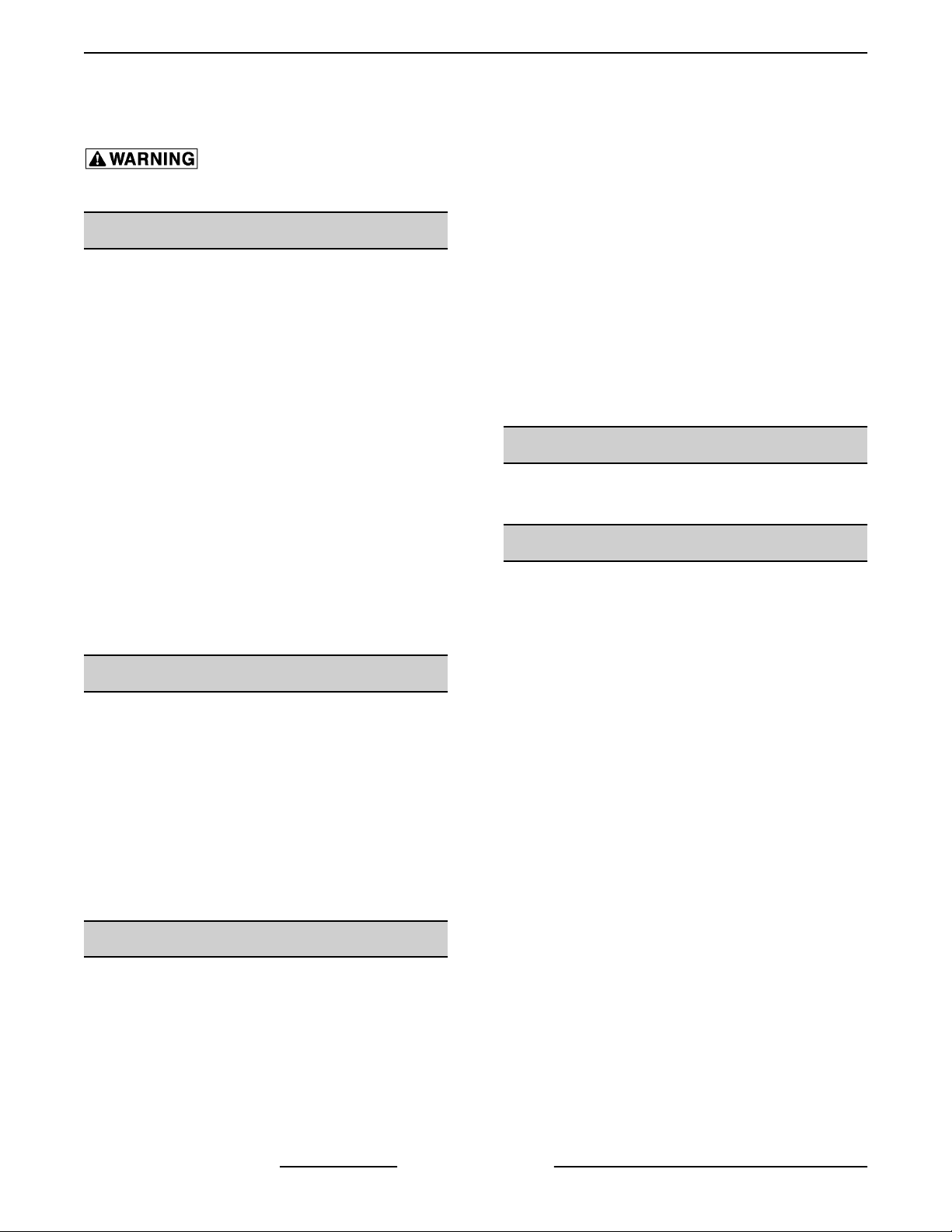
• Adapter to test thermocouple, Johnstone Supply
Part No. H23-226 or equivalent.
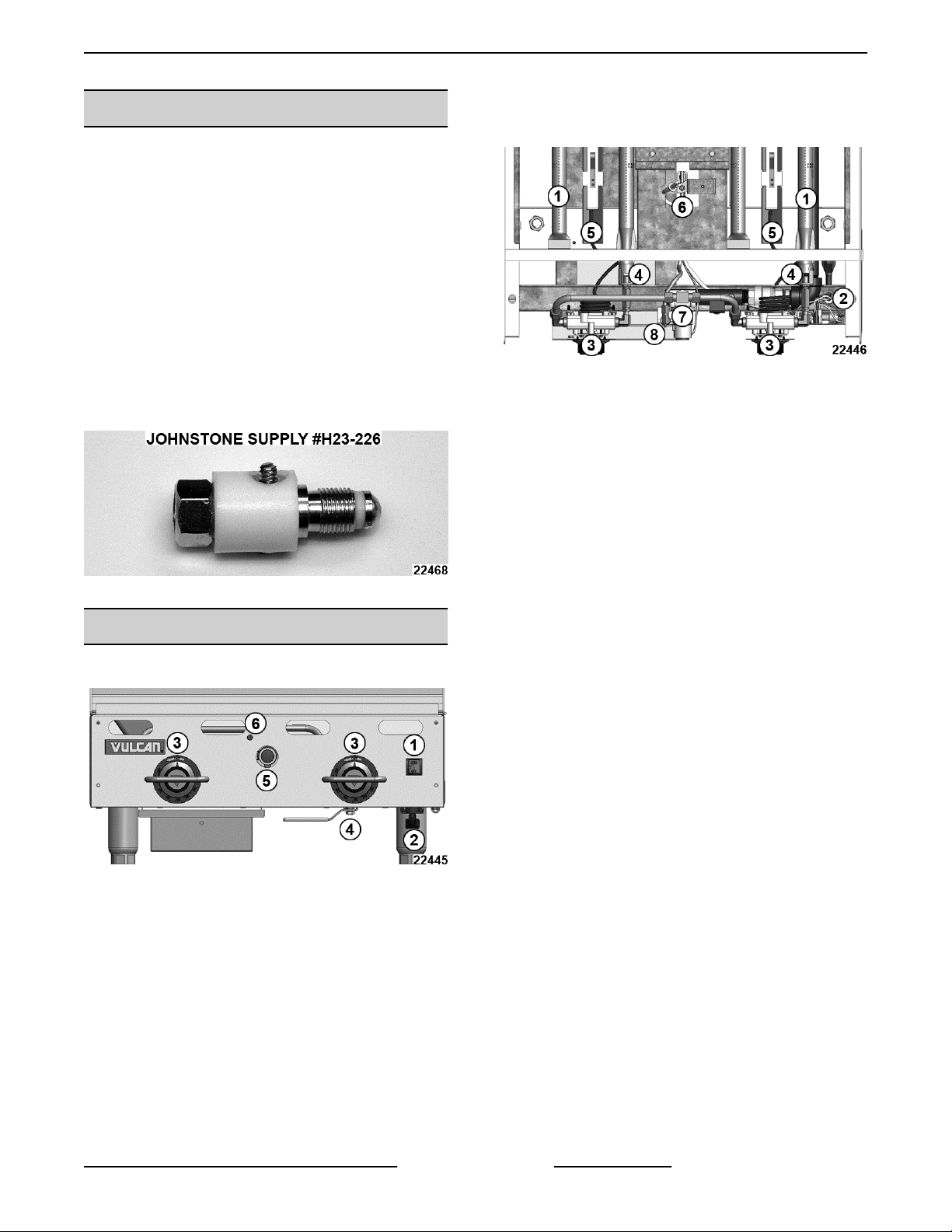
6. Pilot flame adjustment
Top View 924RX
Fig. 3
1. Burner assembly
2. Electric igniter (RX only)
3. Thermostat
4. Orifice
5. Thermostat capillary tube
6. Pilot, igniter (RX only) and thermocouple
Fig. 1
COMPONENT LOCATION
Front View 924RX
Fig. 2
1. Pilot electric ignition system control switch (RX
only)
2. Power cord (RX only)
3. Thermostat
4. Gas shut off valve (RX only)
7. BASO® pilot safety valve
8. Pilot adjustment valve
5. BASO® pilot safety valve
Page 5 of 19 F25383 (0219)
Page 6
Heavy Duty Gas Griddles - REMOVAL AND REPLACEMENT OF PARTS
REMOVAL AND REPLACEMENT OF PARTS
COVERS AND PANELS
Disconnect the electrical power to
the machine and follow lockout /
tagout procedures.
FRONT PANEL
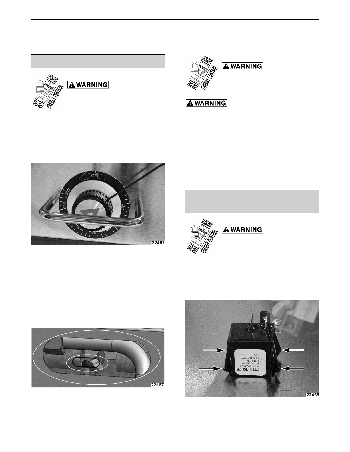
1. Turn all thermostats to off position, loosen set
screw securing thermostat knobs and pull off
knobs.
NOT IN OFF POSITION FOR VIEW
Shut off the gas before servicing the
unit and follow lockout / tagout
procedures.
All gas joints disturbed during servicing must be
checked for leaks. Check with a soap and water
solution (bubbles). Do not use an open flame.
NOTE: It will be necessary to remove the back panel
when changing a burner or to remove excessive
grease build up from flue area.
1. Disconnect gas supply at griddle.
Remove screws securing back panel to griddle.
Fig. 4
2. Remove screws securing front panel to griddle.
3. Pull front panel forward and lay aside. If servicing
a 900RX lay front panel face down in front of unit.
4. Install in reverse order.
NOTE: Before installing front panel, check that lineofsight through the front panel to see both pilot burners
and griddle burners. Move any flexible gas tubing, or
capillary tubing that may obstruct the sight holes.
Install in reverse order.
MOMENTARY POWER SWITCH
(900RX)
Disconnect the electrical power to
the machine and follow lockout /
tagout procedures.
1. Remove FRONT PANEL.
2. Label and disconnect wires from power switch.
3. Squeeze switch retainers and slide switch out
through front of panel.
Fig. 5
BACK PANEL
4. Install in reverse order.
F25383 (0219) Page 6 of 19
Fig. 6
Page 7

Heavy Duty Gas Griddles - REMOVAL AND REPLACEMENT OF PARTS
ELECTRIC IGNITER (900RX)
Disconnect the electrical power to
the machine and follow lockout /
tagout procedures.
1. Remove FRONT PANEL.
2. Push tab to release igniter from frame and pull
out of unit.
2. Measure distance between manifold pipe and
valve for reassembly later.
NOTE: Ignition wires must be routed in front of valves
as shown to prevent them from touching hot heat
shield.
Fig. 8
3. Disconnect all gas lines and thermocouple from
valve.
4. Remove valve from unit.
Fig. 7
3. Label and disconnect wires from electric igniter.
4. Install in reverse order.
BASO SAFETY VALVE
Disconnect the electrical power to
the machine and follow lockout /
tagout procedures.
Shut off the gas before servicing the
unit and follow lockout / tagout
procedures.
All gas joints disturbed during servicing must be
checked for leaks. Check with a soap and water
solution (bubbles). Do not use an open flame.
1. Remove FRONT PANEL.
5. Transfer fittings from old valve to new valve. Use
thread sealant on assembly.
6. Install new valve to same measurement as in
Step 2.
7. Continue to install in reverse order.
THERMOSTAT VALVE ASSEMBLY
Disconnect the electrical power to
the machine and follow lockout /
tagout procedures.
Shut off the gas before servicing the
unit and follow lockout / tagout
procedures.
All gas joints disturbed during servicing must be
checked for leaks. Check with a soap and water
solution (bubbles). Do not use an open flame.
1. Remove FRONT PANEL.
2. Disconnect gas line.
Page 7 of 19 F25383 (0219)
Page 8

Heavy Duty Gas Griddles - REMOVAL AND REPLACEMENT OF PARTS
3. Remove screws securing thermostat mounting
bracket to frame.
Fig. 9
4. Pull capillary tube out from underneath griddle
plate.
5. Transfer fittings from old thermostat to new
thermostat. Use thread sealant.
Fig. 11
11. Inlet to burner must be straight. Adjust thread on
orifice and/or extension to close gap between
orifice and burner to 1/16".
6. Transfer thermostat mounting bracket to new
thermostat.
7. Remove insulator sleeve from old capillary tube
and install on new thermostat.
8. Secure end of insulator sleeve to thick end of
capillary tube with metal tape as shown.
Fig. 10
9. Slide capillary tube all the way into slot
underneath griddle plate until it is fully seated.
10. Carefully insert orifice into burner and secure
thermostat mounting bracket to frame.
Fig. 12
12. Continue to install in reverse order.
F25383 (0219) Page 8 of 19
Page 9

Heavy Duty Gas Griddles - REMOVAL AND REPLACEMENT OF PARTS
BURNER
Disconnect the electrical power to
the machine and follow lockout /
tagout procedures.
Shut off the gas before servicing the
unit and follow lockout / tagout
procedures.
All gas joints disturbed during servicing must be
checked for leaks. Check with a soap and water
solution (bubbles). Do not use an open flame.
1. Remove FRONT PANEL and BACK PANEL.
2. Disconnect gas supply at griddle.
3. Remove screw securing burner to wall.
PILOT, THERMOCOUPLE
ASSEMBLY
Disconnect the electrical power to
the machine and follow lockout /
tagout procedures.
Shut off the gas before servicing the
unit and follow lockout / tagout
procedures.
1. Remove FRONT PANEL.
2. From underneath the front of the griddle, remove
screw securing pilot assembly bracket.
VIEW FROM REAR OF UNIT TO SEE PARTS
Fig. 13
4. At rear of unit, pull burner enough to disengage
burner pin from frame and pull burner out.
Fig. 14
5. Install in reverse order.
6. Adjust as outlined in BURNER ADJUSTMENT.
Fig. 15
3. Carefully lift to disengage bracket from slot and
work assembly down to access parts.
4. With pilot (1, Fig. 16) centered in flash tube
opening, center align ignition ports with both
sides of flash tube (2, Fig. 16). Verify 1/8” gap
between the end of flash tube and burner on both
sides.
Fig. 16
Page 9 of 19 F25383 (0219)
Page 10

Heavy Duty Gas Griddles - REMOVAL AND REPLACEMENT OF PARTS
5. Service assembly as required and assemble in
reverse order being sure bracket is seated in slot
for alignment.
F25383 (0219) Page 10 of 19
Page 11

Heavy Duty Gas Griddles - SERVICE PROCEDURES AND ADJUSTMENTS
SERVICE PROCEDURES AND ADJUSTMENTS
CALIBRATION
LEVEL
The griddle must be level (side-to-side and frontto-back) during operation to ensure proper
performance. Improper leveling can result in
uneven temperature distribution, cold spots, and
possibly damage electrical components.
1. Place a level on the griddle.
2. Adjust legs by turning the bullet feet at the bottom
of each leg. Using pliers or a crescent wrench,
turn the feet counter-clockwise to increase
height, and clockwise to decrease height until
leveling is achieved. Do not extend the legs more
than 1-¾”.
CALIBRATE
1. Each thermostat controls a 12” zone of the
griddle. Using a Surface Probe temperature
measurement device, observe the temperatures
at the center points of the cooking zones. These
points are located by starting 6” from the side
splash (left or right) and every 12” across the
width of the griddle, with all points located 12”
back from the front edge of the griddle plate.
NOTE: Use of infrared thermometers is not
recommended. These devices are highly sensitive to
surface color (clean or dirty), angle of reading and
distance from the unit.
Fig. 17
2. Set thermostats to 350°F and allow to stabilize.
3. Record the temperature tester readouts for each
zone for 3 cycles.
Temperature
Tester turn-off
deg F
Temperature
Tester turn-on
deg F
Turn-Off +
Turn-On
divide
by 2 = average
Total averages
divide by 3 ____
deg F
4. Calculate total average temperature for that
zone.
5. The temperature should be 350°F ±15°F. If not,
continue to next step.
Page 11 of 19 F25383 (0219)
Page 12

Heavy Duty Gas Griddles - SERVICE PROCEDURES AND ADJUSTMENTS
6. Carefully loosen the knob set screw. DO NOT
allow the knob to turn. Carefully remove the knob
from the thermostat shaft, exposing the
temperature dial.
Fig. 21
7. Loosen screws on the temperature dial and
adjust it so that the temperature indicated by the
knob arrow matches the griddle plate
temperature reading. Knob will have to be
carefully placed back on the shaft to verify
adjustment.
Fig. 23
9. Repeat Steps 3 thru 8 for each zone.
PILOT ADJUSTMENT
Using a flathead screwdriver, turn the slotted pilot
adjustment screw clockwise to decrease the flame,
and counterclockwise to increase the flame.
GAS PRESSURE MEASUREMENT
All gas joints disturbed during servicing must be
checked for leaks. Check with a soap and water
Fig. 22
Never adjust the screw in the center of the thermostat
shaft. This will ruin the factory calibration; the
thermostat will no longer operate properly and will
need to be replaced.
8. Once calibration is achieved, tighten the
temperature dial screws and knob set screws.
F25383 (0219) Page 12 of 19
solution (bubbles). Do not use an open flame.
1. Turn the gas supply off at a manual shutoff valve.
2. Remove the control panel.
3. Remove the pressure tap plug and attach
4. Turn gas back on.
5. Light pilot(s).
6. Turn all thermostats on to the maximum setting
7. Turn all the equipment on the same supply line
Fig. 24
manometer.
so that all burners are on.
on.
Page 13

Heavy Duty Gas Griddles - SERVICE PROCEDURES AND ADJUSTMENTS
8. Check gas pressure.
9. Gas pressure should read 4” W.C. for natural and
10” W.C. for propane gas. If not correct, refer to
GAS PRESSURE REGULATOR
ADJUSTMENT.
10. Turn gas supply off, disconnect manometer and
reinstall pressure tap plug.
924RX SHOWN
Fig. 25
GAS PRESSURE REGULATOR ADJUSTMENT
A gas pressure regulator is supplied with the griddle and must be installed as close to the griddle on the gas supply
line as possible. Make sure that the arrow on the underside of the regulator is oriented in the direction of gas flow
to the griddle and the regulator is positioned with the vent plug and adjustment screw upright. Check that vent plug
is not clogged by grease and debris.
Check and set the gas pressure after the regulator is installed. The pressure should be set for 4” water column
(W.C.) for natural gas and 10” W.C. for propane gas while all burners are on.
The supply pressure (upstream of the regulator) should be 7-9” W.C. for natural gas and 11-12” W.C. for propane
gas. At no time should the griddle be connected to supply pressure greater than ½ psig (3.45 kPa) or 14” W.C.
Graphic shows pressure plug location.
Page 13 of 19 F25383 (0219)
Page 14

Heavy Duty Gas Griddles - SERVICE PROCEDURES AND ADJUSTMENTS
Fig. 26
NOTE: MSA models are in same locations. There are no shut off valves.
BURNER ADJUSTMENT
For efficient burner operation, it is important that a
proper balance of gas volume and primary air supply
is maintained to give complete combustion.
Insufficient air supply results in a yellow streaming
flame. Primary air supply is controlled by the air
shutter on the front of the burner venturi. Loosen the
screw on the venturi and adjust the air shutter to just
eliminate yellow tips on the burner flames. Lock the air
shutter in place in place by tightening the screw.
Repeat this procedure as necessary with all burners.
THERMOCOUPLE TEST
1. Unscrew thermocouple fitting from safety valve.
Fig. 27
F25383 (0219) Page 14 of 19
Page 15

Heavy Duty Gas Griddles - SERVICE PROCEDURES AND ADJUSTMENTS
Fig. 28
2. Install thermocouple test adapter finger tight plus
a quarter turn.
3. Install thermocouple into test adapter finger tight
plus a quarter turn.
B. If less than 17 millivolts is measured, install
a replacement thermocouple.
9. Remove test adapter.
NOTE: Over tightening can cause thermocouple tip
to short out.
4. Set VOM to DC millivolt scale and connect (+)
meter lead to pin on thermocouple adapter and
(-) meter lead to thermocouple.
Fig. 29
5. Light pilot flame.
6. Verify that thermocouple is sufficiently immersed
in flame. Adjust pilot valve to allow more gas flow
if necessary.
7. With thermostat off, allow pilot to burn for 3-4
minutes to stabilize voltage output from
thermocouple.
8. Verify thermocouple output voltage.
A. If 25 - 35 millivolts is measured, the
thermocouple is functioning properly.
Page 15 of 19 F25383 (0219)
Page 16

Heavy Duty Gas Griddles - ELECTRICAL OPERATION
ELECTRICAL OPERATION
ELECTRICAL DIAGRAM
Fig. 30
F25383 (0219) Page 16 of 19
Page 17

Heavy Duty Gas Griddles - ELECTRICAL OPERATION
Fig. 31
Page 17 of 19 F25383 (0219)
Page 18

Heavy Duty Gas Griddles - TROUBLESHOOTING
TROUBLESHOOTING
TROUBLESHOOTING
SYMPTOMS POSSIBLE CAUSES
1. Power cord unplugged.
2. Igniter switch malfunction.
No spark to ignite pilot gas.
Sparks but gas does not ignite.
Gas pilot ignites but will not maintain flame.
3. Shorted electrode on ignitor.
4. Ignitor cable malfunction.
5. Interconnecting wiring malfunction.
6. Electric Igniter Module malfunction.
1. Service gas valve closed.
2. Gas supply not purged of air. Depress pilot safety button until
air is purged.
3. Gas supply off or insufficient gas pressure.
4. Adjust pilot valve to allow more gas flow.
5. Safety valve malfunction.
1. Air blowing pilot out. Prevent air flow from affecting unit.
2. Gas supply not purged of air. Depress pilot safety button until
air is purged.
3. Adjust pilot valve to allow more gas flow.
4. Thermocouple not sufficiently immersed in flame. Adjust
accordingly.
5. Thermocouple malfunction. Refer to THERMOCOUPLE
TEST.
6. Obstructed pilot orifice.
7. Insufficient gas pressure.
8. Safety valve malfunction.
1. Gas pressure incorrect or fluctuating.
2. Obstructed flue.
Gas burners ignite but will not maintain flame.
One or more burners have lower flame level
than the others.
F25383 (0219) Page 18 of 19
3. Gas orifice obstructed, improperly aligned / spaced, or
incorrect.
4. Burner malfunction.
1. Check gas pressure.
2. External air flow or vent hood problems may agitate affected
burners.
3. Gas orifice obstructed, improperly aligned / spaced, or
incorrect.
4. Adjust burner air shutter.
Page 19

Heavy Duty Gas Griddles - TROUBLESHOOTING
SYMPTOMS POSSIBLE CAUSES
1. Check gas pressure.
2. Check that burner is properly seated.
3. Check that burner ignition ports, pilot flash tube and pilot burner
One burner has a delayed ignition; a several
second lapse when the burner actually lights.
are all aligned.
4. Gas orifice obstructed, improperly aligned / spaced, or
incorrect.
5. Check burner shutter adjustment.
6. Check pilot flame adjustment.
1. Gas shut off valve not completely open.
2. Thermostats need calibrated. See CALIBRATION section.
3. Thermostat malfunction.
Excessive or low heat.
Heat does not come on when the thermostat
is turned on.
4. Gas pressure incorrect.
5. Unit's gas regulator not installed or malfunctioning.
6. Incorrect gas type.
7. Gas orifice obstructed or incorrect.
1. Pilot burner not lit.
2. Griddle shut-off valve not in ON position.
3. Low gas pressure.
4. Thermostat malfunction.
Page 19 of 19 F25383 (0219)
 Loading...