

Page 1
SERVICE MANUAL
ABC Combi Gas Oven
ABC7G NAT / ML-137715
NATP / ML-137717
- NOTICE -
This Manual is prepared for the use of trained Vulcan Service
Technicians and should not be used by those not properly
qualified.
This manual is not intended to be all encompassing. If you have
not attended a Vulcan Service School for this product, you should
read, in its entirety, the repair procedure you wish to perform to
determine if you have the necessary tools, instruments and skills
required to perform the procedure. Procedures for which you do
not have the necessary tools, instruments and skills should be
performed by a trained Vulcan Service Technician.
The reproduction, transfer, sale or other use of this Manual,
without the express written consent of Vulcan, is prohibited.
This manual has been provided to you by ITW Food Equipment
Group LLC ("ITW FEG") without charge and remains the property
of ITW FEG, and by accepting this manual you agree that you will
return it to ITW FEG promptly upon its request for such return at
any time in the future.
A product of Vulcan-Hart 3600 North Point Blvd Baltimore, MD 21222
F45491 Rev. B (0518)
Page 2

ABC Combi Gas Oven
TABLE OF CONTENTS
SERVICE UPDATES ....................................................................................... 4
SERVICE UPDATES - ABC COMBI GAS OVEN ......................................................... 4
GENERAL .................................................................................................. 5
INTRODUCTION ....................................................................................... 5
OPERATION, CLEANING AND MAINTENANCE ........................................................ 5
TOOLS ................................................................................................. 5
LUBRICATION ......................................................................................... 5
WATER QUALITY STATEMENT ........................................................................ 6
SPECIFICATIONS ...................................................................................... 7
UPGRADE ABC COMBI FIRMWARE ....................................................................... 8
FIRMWARE VERSION HISTORY ....................................................................... 8
FIRMWARE UPDATE PROCEDURE .................................................................. 10
USB ERROR MESSAGES ............................................................................. 11
REMOVAL AND REPLACEMENT OF PARTS .............................................................. 13
PANELS .............................................................................................. 13
INNER DOOR ......................................................................................... 14
INNER DOOR LATCH ................................................................................. 14
DOOR LAMP .......................................................................................... 15
DOOR LATCH ........................................................................................ 15
DOOR SWITCH ....................................................................................... 17
MAIN CONTROL BOARD ............................................................................. 18
OXYGEN SENSOR ................................................................................... 18
OXYGEN SENSOR BOARD ........................................................................... 19
FERRITE ............................................................................................. 20
MOTOR CONTROL BOARD ........................................................................... 21
CONTROL BOX COOLING FAN ....................................................................... 21
CONTROL PANEL .................................................................................... 22
CONTROL PANEL COOLING FAN .................................................................... 23
ON / OFF SWITCH .................................................................................... 24
KNOB & ENCODER ................................................................................... 25
DISPLAY BOARD ..................................................................................... 25
MEAT PROBE SOCKET ............................................................................... 26
REAR COOLING FAN ................................................................................. 27
HIGH-LIMIT THERMOSTAT ........................................................................... 28
CAVITY INTAKE TUBE ASSEMBLY ................................................................... 29
CAVITY VENT MOTOR ............................................................................... 30
CAVITY VENT SWITCHES ............................................................................ 31
TRANSFORMER ...................................................................................... 31
TEMPERATURE SENSOR (RTD1) .................................................................... 33
DRAIN WATER CONDENSATE VALVE ................................................................ 34
DRAIN WATER THERMOCOUPLE .................................................................... 34
HUMIDITY VALVE .................................................................................... 35
CONVECTION FAN BAFFLE .......................................................................... 36
CONVECTION FAN MOTOR .......................................................................... 37
GAS VALVE .......................................................................................... 39
IGNITOR .............................................................................................. 39
FLAME SENSOR ...................................................................................... 40
INDUCER BLOWER ................................................................................... 40
HEAT EXCHANGER ASSEMBLY ...................................................................... 42
DRAFT INDUCER PRESSURE SWITCH ............................................................... 44
IGNITION MODULE ................................................................................... 44
SERVICE PROCEDURES AND ADJUSTMENTS ........................................................... 46
CONFIGURATION MODE (1972) - GAS ............................................................... 46
F45491 Rev. B (0518) Page 2 of 119
Page 3

ABC Combi Gas Oven
CALIBRATING OXYGEN SENSOR BOARD ........................................................... 53
CHECK OXYGEN SENSOR DATE CODE (REPLACEMENT SENSORS) ............................... 54
TEMPERATURE SENSOR (RTD1) TEST .............................................................. 55
TEMPERATURE CALIBRATION ....................................................................... 55
EXTERNAL MEAT PROBE THERMOCOUPLE CALIBRATION ......................................... 56
CAVITY VENT SWITCH TEST AND ADJUSTMENT .................................................... 56
DOOR TO CONTROL PANEL ALIGNMENT ............................................................ 58
DOOR SWITCH ADJUSTMENT ....................................................................... 61
TRANSFORMER RESISTANCE CHECK ............................................................... 61
MOTOR RESISTANCE CHECK ....................................................................... 63
GAS VALVE PRESSURE CHECK AND ADJUSTMENT ................................................ 64
FLAME SENSE VOLTAGE TEST (FENWAL SERIES 35-61) ............................................ 65
DRAFT INDUCER TEST .............................................................................. 66
COMBUSTION ANALYSIS ............................................................................ 66
ELECTRICAL OPERATION ................................................................................ 68
COMPONENT FUNCTION ............................................................................ 68
ELECTRICAL PANEL COMPONENT LOCATION ...................................................... 71
SEQUENCE OF OPERATION ............................................................................. 72
CONDITIONS ......................................................................................... 72
ON/OFF SWITCH (SW4) TURNED ON, (NO CALL FOR HEAT) ........................................ 73
ON/OFF SWITCH (SW4) ON & WITH CALL FOR HEAT ................................................ 74
ON/OFF SWITCH (SW4) ON & WITH CALL FOR HEAT & CALL FOR HUMIDITY ....................... 75
OTHER SEQUENCES ................................................................................. 76
CIRCUIT BOARD LAYOUTS .............................................................................. 79
MAIN BOARD CONNECTIONS ........................................................................ 79
MOTOR BOARD ...................................................................................... 82
IGNITION MODULE ................................................................................... 83
WIRING DIAGRAMS ...................................................................................... 84
TERMINAL BLOCKS AND TRANSFORMER ........................................................... 85
MAIN BOARD ......................................................................................... 86
MOTOR BOARD ...................................................................................... 87
IGNITION MODULE ................................................................................... 88
COOLING FANS ...................................................................................... 89
DIAGNOSTICS / TROUBLESHOOTING ................................................................... 90
SERVICE MODE (1963) ............................................................................... 90
ERROR CODES ...................................................................................... 96
OVEN TROUBLESHOOTING ........................................................................ 102
IGNITION CONTROL MODULE TROUBLESHOOTING ................................................... 119
IGNITION CONTROL MODULE TROUBLESHOOTING ............................................... 119
© VULCAN 2018
Page 3 of 119 F45491 Rev. B (0518)
Page 4

ABC Combi Gas Oven - SERVICE UPDATES
SERVICE UPDATES
SERVICE UPDATES - ABC COMBI
GAS OVEN
May 2018
1. Updated all chapters due to firmware update in
this service manual.
NOTE: Upgrade ABC Combi Firmware 04-24-17.
2. FIRMWARE VERSION HISTORY .
3. FIRMWARE UPDATE PROCEDURE .
4. MEAT PROBE SOCKET .
F45491 Rev. B (0518) Page 4 of 119
Page 5
ABC Combi Gas Oven - GENERAL
GENERAL
INTRODUCTION
General
This manual is for ABC7 Combi ovens. Ovens
feature a powered vent damper, and an
advanced digital control panel with digital display
for setting cook TEMPERATURE, TIME, and
HUMIDITY.
Heating
The ABC Combi oven reaches baking
temperature of 350°F at 0% humidity in
approximately 5½ to 6 minutes; however, a 20minute preheat is recommended.
Combi Ovens
Combi ovens provide convection heat, steam
heat or a combination of both in a single
compartment cooking chamber. Humidification is
provided by water injection into oven cavity.
Water is injected by means of an internal nozzle,
and vaporizes on contact with hot interior
surfaces.
Steam System
All combi ovens come with a boilerless flash
steaming system which provides a quick
response time as well as excellent cooking
results.
4. Inclined manometer - Dwyer Cat #1227 or
equivalent.
5. 1/4" T with 1/4" tubing.
6. Temperature tester (thermocouple type).
7. Field service grounding kit.
Special
1. Combustion analyzer.
2. M6 socket head cap screw 3" long (hardened
black oxide finish) for removing convection fan
from motor shaft.
3. Gear puller to remove CONVECTION FAN
MOTOR.
4. USB Drive (Part # 00-443444).
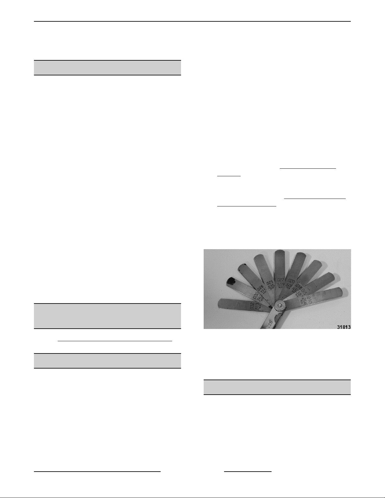
5. No-Go / Go Gauges for DOOR TO CONTROL
PANEL ALIGNMENT.
A. No-Go Gauge - .200"
• Use .032", .030", .028", .025", .022", .
020", .018", .015", and .010" feeler
gauges to make a .200" No-Go gauge.
All information, illustrations and specifications
contained in this manual are based on latest
product information available at time of release.
OPERATION, CLEANING AND
MAINTENANCE
Refer to Installation & Operation Manual (F47110) for
specific operating instructions.
TOOLS
Standard
1. Standard set of hand tools.
2. Metric set of hand tools.
3. VOM with minimum of NFPA-70E CAT III 600V,
UL/CSA/TUV listed. Sensitivity of at least 20,000
ohms per volt. Meter leads must also be rated at
CAT III 600V. Clamp on type amp meter with
minimum of NFPA-70E CAT III 600V, UL/CSA/
TUV listed.
Fig. 1
B. Go gauge - .119"
• Use .032", .030", .028", .025" and .004"
feeler gauges to make a .119" Go
gauge.
LUBRICATION
NOTE: Ovens have self-lubricating composite
bearings. No lubrication required.
Page 5 of 119 F45491 Rev. B (0518)
Page 6
ABC Combi Gas Oven - GENERAL
WATER QUALITY STATEMENT
The fact that a water supply is potable is no guarantee that it is suitable for steam generation. Proper water quality
can improve the taste of the food prepared in the oven, reduce scale build-up or corrosion, and extend equipment
life. Local water conditions vary from one location to another and can change throughout the year. The
recommended water treatment for effective and efficient use of this equipment will vary depending on the local
water conditions. Your water supply must be within the general guidelines outlined in the chart below at all times
during use of this machine or service issues not covered under warranty may result.
Water hardness should be treated by removing the impurities (water softener with carbon block or dechlorinator
and/or in-line water treatment). Low water hardness may also require a water treatment system to reduce potential
corrosion. Water treatment has been shown to reduce costs associated with machine cleaning, reduce deliming
and reduce corrosion of metallic surfaces.
Daily washing and rinsing of the cavity is required. In some cases, it may be needed more than once a day to prevent
compounding of contaminants deposited inside cavity even with acceptable filtration. Failure to wash and rinse
down the cavity daily could result in damage of the oven cavity and interior parts. A Reverse Osmosis water
treatment system can be installed to eliminate chlorides or other contaminates from the water if needed.
NOTE: Failure to properly maintain water quality or preventative procedures for water can lead to issues not
covered under warranty.
Plumbing connections must comply with the
applicable sanitary, safety and plumbing codes.
WATER SUPPLY GENERAL GUIDELINES
1
Supply Pressure (dynamic flow) 30-60 psig
Hardness less than 3 grains (17.1 ppm = 1 grain of hardness)
Silica less than 13 ppm
Chloramines
Chlorides
2
Total Chlorine
2
4
zero
less than 30 ppm
zero
3
PH range 7-8
Undissolved Solids less than 5 microns
1
Testing of water is always done AFTER water
filter or water treatment used. Water quality does
change with usage and should be checked after
idle times to see if the condition worsens.
2
A carbon block filter system should always be
used to remove Chlorine and Chloramine. If a
water softener is used, a carbon block is still
required. Check with your local water treatment
specialist for proper sizing and replacement
intervals for the carbon block cartridge.
3
If the Chlorides exceed 30 ppm and the oven is
used more than 8 hours during the day in steam
or combination mode, the cavity will require
rinsing every 8 hours. Failure to do so will result
in corrosion and rusting of the oven cavity and
interior parts. A Reverse Osmosis water treatment
system can be installed to eliminate chlorides
from the water and reduce the hardness.
Preventative washing and rinsing may be needed
more than once a day to prevent compounding of
contaminants inside cavity.
4
Total Chlorine of 4.0 ppm is the max limit for the
building water supply. A carbon block filter must
still be used to remove all Chlorine and
Chloramines from the water. Failure to do so will
result in corrosion and rust in the cooking cavity,
which is not covered under warranty.
F45491 Rev. B (0518) Page 6 of 119
Page 7
ABC Combi Gas Oven - GENERAL
SPECIFICATIONS
Data
Appliances equipped with a flexible electric
supply cord are provided with a three prong
grounding plug. It is imperative that this plug be
connected into a properly grounded three prong
receptacle. If the receptacle is not the proper
grounding type, contact an electrician. Do not
remove grounding prong from this plug.
Electrical and grounding connections must
comply with the applicable portions of the
National Electrical Code and / or other local
electrical codes.
NOTE: The spark ignition in this appliance can cause
electrical noise that can false trigger the GFCI
detection. Some GFCI’s are more sensitive than
others. The use of a higher trip tolerance GFCI will
reduce nuisance tripping. Contact Technical Support
for more information.
The drain connection must be plumbed with a
minimum of 1" air gap. Drain water cannot be
greater than 140°F, upon discharge. There is a
1" NPT male port for drain. Drain plumbing, not
supplied, should have a constant slope towards
floor drain. Do not connect solidly to floor or other
drains.
Supply Voltage
Volts Amps Hertz Phase
120 5.0 60 1
Supply Gas Pressure Input
Natural Propane BTU/HR
5" - 14" W.C. 11" - 14" W.C. 80,000
Water Supply
A cold water supply with a flow pressure of 30 to
60 psi is required.
There is a 3/4" garden hose fitting located on rear
of machine labeled FILTERED. This inlet must be
connected to approved filter system. Failure to
connect oven to approved filter system will void
warranty.
There is also a 3/4" garden hose fitting located
on rear of machine labeled NON-FILTER.
Plumbing Connections
Plumbing connections must comply with the
applicable sanitary, safety and plumbing codes.
Drain Connection
Page 7 of 119 F45491 Rev. B (0518)
Page 8

ABC Combi Gas Oven - UPGRADE ABC COMBI FIRMWARE
UPGRADE ABC COMBI FIRMWARE
FIRMWARE VERSION HISTORY
This section contains history of ABC7 Combi Oven Firmware. The release date of Firmware is how it is identified.
The table below lists release date and a short explanation of features / fixes which were introduced with that
particular version.
NOTE: Current version of firmware loaded into oven can be identified with Parameter P0 in Service Mode (1963)
or Configuration Mode (1972). The current version of in-application program (IAP) shows briefly on the Timer display
when USB is inserted.
Firmware Version /
(Release Date)
022514 (02-25-14)
Comments
• First production release FIRMWARE.
• IAP6.15 (in-application program) loaded to read USB port.
• Rev 11 oxygen board code.
081114 (08-11-14)
• Main board identified with ‘red wire’ on T1, (256k flash, STM32F207VCT6, 01/14-08/16,
#266-#1185).
• IAP6.15 (in-application program) loaded to read USB port.
• Rev 11 oxygen board code.
• Main board identified with ‘red wire’ on T1, (256k flash, STM32F207VCT6, 01/14-08/16,
#266-#1185).
• Main board identified with ‘red wire’ on T1, (1024k flash, STM32F207VGT6, 10/16,
#1224-#1316).
Serial Numbers
• 541074335 (-NAT)
• 541074349 (-208V)
• 541075058 (-240v)
• 541074355 (-480v)
Combi Changes
Fixed a motor board hardware issue with the E6 error. Motor current sense circuit would
lock up and the oven sensed a “false positive” current going to the convection motor,
causing an E6 motor.
Fixed an issue with the P4, P5 and P6 custom temperature settings. It fixes an issue with
the custom temps feature, in which initial lowest temp value when turning up from standby
could be out of P15/16 range, if the only enabled custom temps are above/below P15/16.
In Configuration Mode (1972), increases maximum temperature setting in parameter P15
to 482F.
NOTE: Ovens with Serial Numbers prior to 541073334 must have their High Limit Thermostat
changed before the setting of the maximum temperature can be set above 450F.
F45491 Rev. B (0518) Page 8 of 119
Page 9

ABC Combi Gas Oven - UPGRADE ABC COMBI FIRMWARE
Firmware Version /
(Release Date)
Comments
• IAP6.21 (in-application program) loaded to read USB port with Rev 12 oxygen board
code.
• Main Board identified with ‘green wire’ on T1, (1024k flash, STM32F207VGT6, 01/17+,
#1317+).
• Oxygen Sensor, Revision C, August 2016.
Starting Serial numbers FIRMWARE
• 541083050 (-NATP) or 541083053 (-208P, -240P, -480P)
• 541083068 (-NAT) or 541083068 (-208, -240, -480)
Backward Compatibility
The 4-24-17 firmware is backward compatible to ovens with 8-11-14 or 2-25-14. It is
highly recommended that the upgrade to IAP 6.21 and Rev 12 oxygen board software
be completed at the same time. However, if the IAP and oxy boards are not also
upgraded, the oven will still work but without benefit of the E14 and E28 diagnostics and
new functionality thereof.
IAP Changes
Work-around for damaged USB port on Main board. If proper operation of USB port on
main board is not properly detected in 1 second, the USB port is ignored. Fixed rare issue
with USB_HOST_CONN shown on display interrupting normal oven operation. Pairs with
Combi firmware addition of E14 error.
042417 (04-24-17)
Combi Changes
• Changed Service Test Mode (1963).
• Added additional oxygen sensor tests: o5, o6, o7, Pb.
• Added error codes: E14 (USB-requires IAP 6.21), E21 (motor speed), E29 (rtd).
• Removed error code E16 removed & replaced with E22, E23, E24, E25, E26, E27,
E28 (E28 Requires Revision 12 oxygen board firmware).
• Changed Configuration Mode (1972).
• Changed P12 (motor speed). Added P21 (probe calibration), P29 (cook 2 probe UI),
P34 (humidification method).
• Changed defaults P25 and P26 for drain water tempering for new style drain with
bent tube assembly, current production for starting s/n’s:
541082447 (-NAT)
OR
541082442 (-208)
541082482 (-240)
541082425 (-480)
• Added P76 (factory only) to calibrate TC1 & TC2 thermocouple based on TC2
external meat probe thermocouple analog offset (after 2-minute temperature
stabilization). Turning Timer knob switches Timer display to show uncalibrated
probe temp (TC2 with P76 analog offset applied) for ease of calibration.
• Changed User Interface.
Page 9 of 119 F45491 Rev. B (0518)
Page 10

ABC Combi Gas Oven - UPGRADE ABC COMBI FIRMWARE
Firmware Version /
(Release Date)
Comments
• Additional functionality of Cook-to-Probe and Fan Speed Control with push button
encoder. Added fan speed to the time and humidity “recalled’ settings when the on/
off switch is turned on. (If oven is equipped: ABCx-xxxP devices only. Pairs with
P29, P12, P21.)
• Changed Operate Mode.
• Removed the temperature augmentation to 220F, at temperature setpoints of
212-220F for enhanced steaming.
• Removed sensor based valve/vent operation at the 100% humidity setpoint case
and replaced with continual flow of Y9 low hum water valve while vent remains
closed. Defaults to sensor based humidification at humidity setpoints of <100%.
Pairs with configuration setting P34 (default=dis) for enhanced steaming.
• Modified transfer function and calculations for additional accuracy on TC2
thermocouple reading for the cook-to-probe feature. Applies to all thermocouples.
Pairs with Main board hardware modifications to the probe circuit as indicated by
the “green” wire on T1.
• Removed all audible “error beeps” for all non-critical errors.
• Fixed a rare issue with the timer expiring/alarming when not previously set. Or which
“no” or “HEAT” could show for a split second after closing the door.
• General Fixes:
• Change project target was STM32F207IGH6, 1M flash, now STM32F207VGT6, 1M
flash corresponds to hardware change on Main board.
• Update to stm32 2.28 support package. Double the heap and stack size. (Software
maintenance.)
FIRMWARE UPDATE PROCEDURE
1. Obtain a copy of ABCombi.bin file and the
IAP.bin file from the Hobart Service Resource
Center and load it onto a USB flash drive (thumb
drive).
NOTE: The file must be loaded in the root directory
in the USB flash drive.
2. Remove RIGHT PANEL.
3. Re-apply power to oven and ensure door is
closed.
4. Review and record oven's unique information.
NOTE: The oven's internal memory is reconfigured,
and set to factory default when updating from 8-11-14
to 4-24-17. It is necessary to record any unique
information.
B. Review (or Error Download to USB Flash
Drive) the Error Log and Counter data in
1963 Service Test Mode for your records or
analysis.
NOTE: Oven memory will not be overwritten when
upgrading from 4-24-17 to future revisions.
5. Place the Oven in Idle Mode (Temperature
display - - -).
• No Set Temperature.
• Not in service test mode (1963).
• Not in configuration mode (1972).
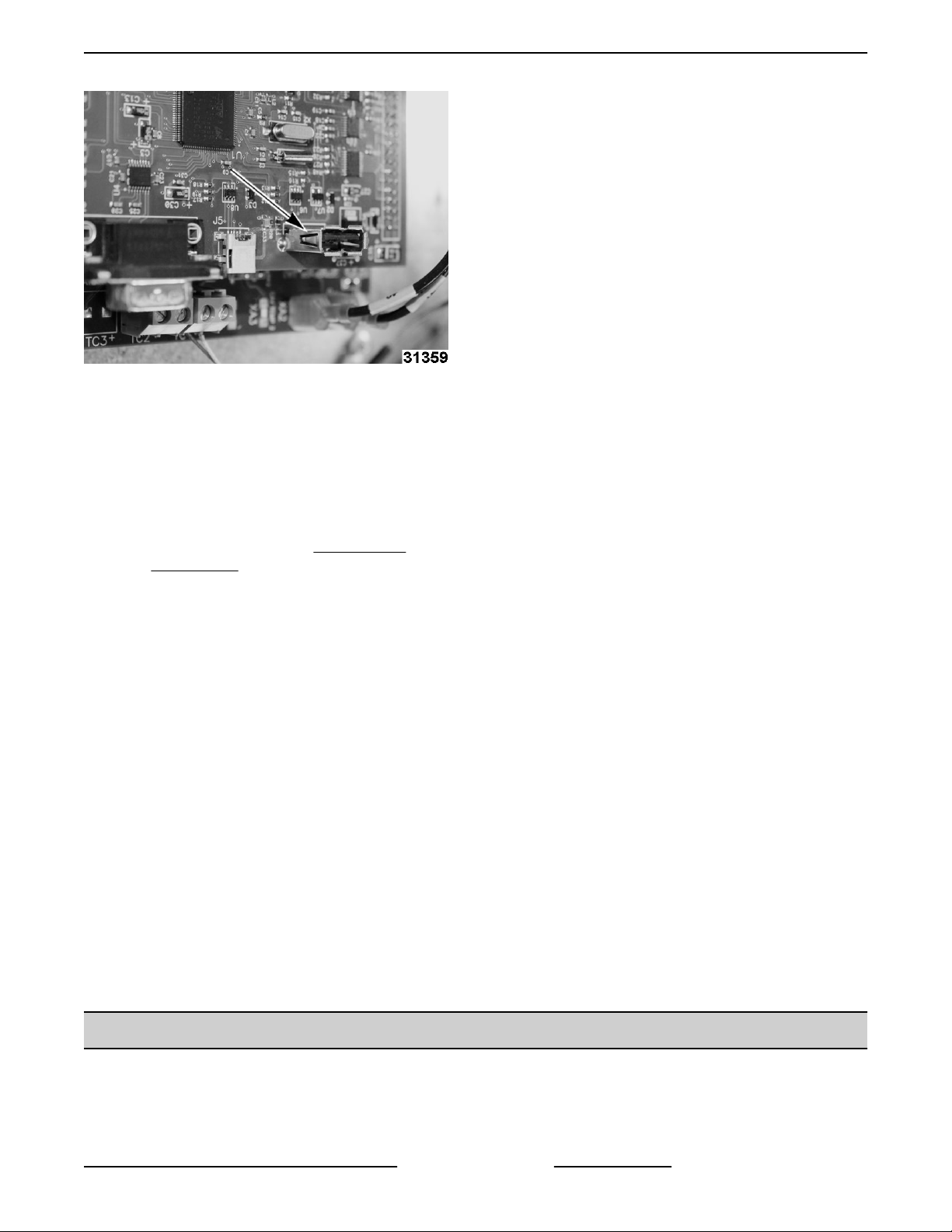
6. Insert the USB flash drive into the oven’s USB-A
port.
NOTE: The convection fan motor may or may not
come on when the USB flash drive is inserted.
A. Write down any custom settings in
Configuration Mode (1972) Parameters P4,
P5, P6. These settings must be reconfigured after firmware update.
F45491 Rev. B (0518) Page 10 of 119
Page 11
ABC Combi Gas Oven - UPGRADE ABC COMBI FIRMWARE
Fig. 2
7. View the LED displays on the front of the oven.
• The oven briefly flashes the in-application
program version IAP 6.21 on the timer
display.
8. "Usb Flsh n_y” appears on the display.
• If something other than "Usb Flsh n_y" is
displayed, then refer to USB ERROR
MESSAGES.
• If "n" is selected with the humidity knob
(turned to the left, ccw), the oven will return
to Idle mode. Firmware not updated.
• If "y" is selected (turned to the right, cw), the
humidity display briefly changes to show
"yes", then "del" as the necessary flash is
deleted, then begins showing a percentage
complete from 0-100 as the software image
is flashed. When flashing is complete
(usually after a few seconds), the humidity
display briefly shows "don", which indicates
the software flashed correctly. Oven returns
to the Idle Mode (Temperature display - - -).
Firmware is updated.
9. Enter Configuration Mode (1972),
• Verify that parameter P0 now shows
4-24-17 as the firmware revision code.
• Enter oven hour count, found in parameter
P18 on the service ticket.
NOTE: Updating the IAP is highly recommended
when updating firmware from 8-11-14 to 4-24-17 or
later versions. Required for proper operation of the
E14 error and “USB HOST COnn” fix.
NOTE: When updating firmware from 4-24-17 to later
versions skip to step 11.
A. Continue in configuration mode (1972), with
the USB flash drive remaining inserted.
B. Turn temperature knob clockwise to P72.
“2000” shows on timer display.
C. Turn timer knob counterclockwise to enter
password “1972” allowing access. "Eng"
shows on timer display.
D. Turn temperature knob counterclockwise to
P65. Display will show “FIAP no”.
E. Turn humidity knob clockwise to select “yes”
to request IAP firmware update. Display will
show “IAP FLSH n_y”.
NOTE: If oven does not respond, select “yes” again.
F. Turn humidity knob counterclockwise to
select “y” and initiate IAP download.
Selecting "n" will cancel back to P65.
• Display will show “USb flsh don”.
• Display will briefly show “IAP 6.21”
(watch for this to verify the IAP updated
correctly).
• Display will show “IAP FLSH n_y”,
asking to re-flash the oven firmware
(not IAP firmware) again. Select "n",
but you can select either “y” or “n”
without issue.
• Oven exits configuration mode, and
returns to Idle Mode (Temperature
display - - - ).
11. Remove USB flash drive.
Updating the Oxygen Sensor Board Firmware
Oxygen sensor board firmware cannot be
updated remotely and must be replaced to get
the current revision. Contact your local Hobart
Service office for the latest replacement part.
10. Update the In-Application Program (IAP).
USB ERROR MESSAGES
Page 11 of 119 F45491 Rev. B (0518)
Page 12

ABC Combi Gas Oven - UPGRADE ABC COMBI FIRMWARE
Error Message Corrective Action
Usb Host Con
or
Usb Host Enu
Usb No Fil: The ABCombi.bin file was not found on USB drive. Reload ABCombi.bin file.
USB Fail < 1, 2 or 3 > USB drive needs to be formatted in FAT32 format. If this fails use a different USB drive.
USB Fail < 4-5, 7-8 or
15-18 >
USB Fail < 9-14>
Remove USB drive. When temperature display returns to "---", reinsert USB drive.
Remove USB drive. When temperature display returns to "---", reinsert USB drive.
If error persists, use a different USB drive.
Remove USB drive. When temperature display returns to "---", reinsert USB drive.
If error persist, replace Main Control Board
F45491 Rev. B (0518) Page 12 of 119
Page 13
ABC Combi Gas Oven - REMOVAL AND REPLACEMENT OF PARTS
REMOVAL AND REPLACEMENT OF PARTS
PANELS
Disconnect the electrical power to
the machine and follow lockout /
tagout procedures.
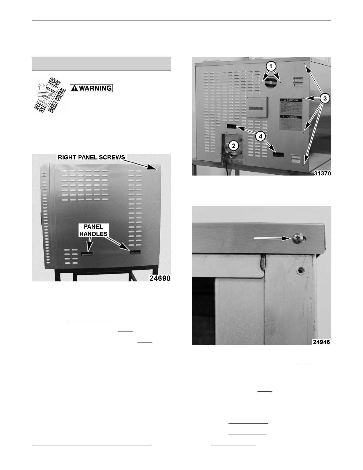
Right Panel
1. Remove four right panel screws.
2. Lift right panel up and back using handles.
Fig. 4
Fig. 3
3. Reverse procedure to install.
Rear Panel
1. Remove RIGHT PANEL.
2. Remove two fan screws (1, Fig. 4).
3. Remove six utility panel screws (2, Fig. 4).
NOTE: Bottom two utility screws only support utility
panel and can be left assembled.
4. Remove screw in the upper right hand corner on
right side of oven.
Fig. 5
5. Remove four rear panel screws (3, Fig. 4).
NOTE: Hold onto one panel handle to prevent rear
panel from falling.
6. Lift with handles (4, Fig. 4) to remove.
7. Reverse procedure to install.
Left Panel
1. Remove RIGHT PANEL.
2. Remove REAR PANEL.
Page 13 of 119 F45491 Rev. B (0518)
Page 14
ABC Combi Gas Oven - REMOVAL AND REPLACEMENT OF PARTS
3. Remove screw in the upper left hand corner on
left side of oven.
4. Lift left panel up and back towards the rear of unit.
Fig. 8
4. Place inner door in a secure location to prevent
damage.
Fig. 6
5. Reverse procedure to install.
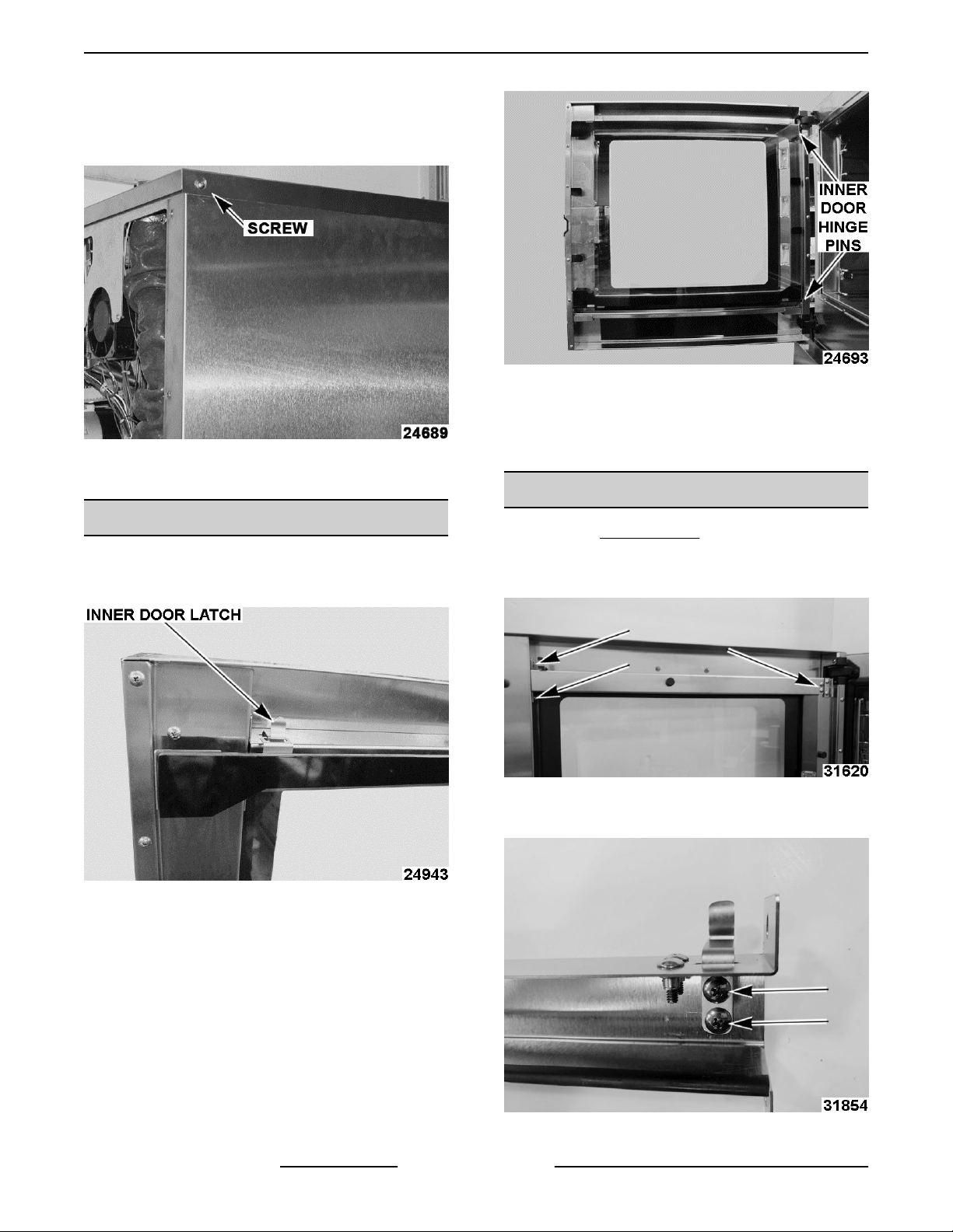
INNER DOOR
1. Open oven door.
2. Unlatch inner door using inner door latch.
Fig. 7
5. Reverse procedure to install.
INNER DOOR LATCH
1. Remove INNER DOOR.
2. Remove upper door stiffener screws from both
ends and remove upper door stiffener.
Fig. 9
3. Remove inner door latch screws.
3. Lift inner door up off door hinge.
F45491 Rev. B (0518) Page 14 of 119
Fig. 10
Page 15
ABC Combi Gas Oven - REMOVAL AND REPLACEMENT OF PARTS
4. Reverse procedure to install.
Apply Blue Loctite 243 to inner door latch screws and
inside stiffener screws.
Apply Purple Loctite 222 to the upper door stiffener
screws.
Tighten screws to 24 in. lb.; do not overtighten.
5. Check for proper operation.
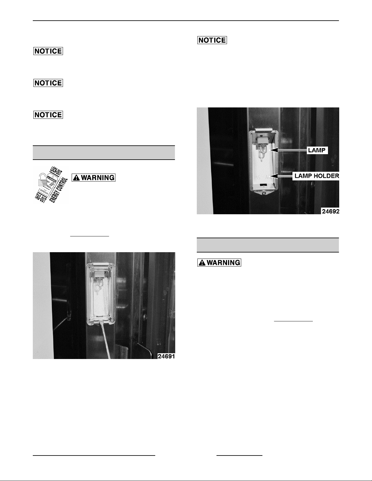
DOOR LAMP
Disconnect the electrical power to
the machine and follow lockout /
tagout procedures.
Do not touch Halogen lamp with bare hands. If lamp
is exposed to oil from skin, life of the Halogen lamp will
be reduced. Skin oil may be removed with alcohol
while lamp is cold.
NOTE: Use a clean rag or paper towel to handle
replacement lamp. Ensure lamp is free from oil and
dirt before replacing.
NOTE: Previous production ovens had three 5W
lamps. Current production ovens have one 10W lamp.
1. Remove INNER DOOR.
2. Insert screwdriver in slot just above screw.
Fig. 11
3. Push in tab to free glass cover from lamp holder.
4. Grasp lamp using cloth and remove from lamp
socket.
Fig. 12
5. Reverse procedure to install.
DOOR LATCH
The oven and its parts are hot. Use care when
operating, cleaning or servicing the oven. The
cooking compartment contains live steam. Stay
clear when opening door.
Door Cam
1. Open door and remove INNER DOOR.
2. Remove door lock cover.
Page 15 of 119 F45491 Rev. B (0518)
Page 16
ABC Combi Gas Oven - REMOVAL AND REPLACEMENT OF PARTS
Fig. 15
Fig. 13
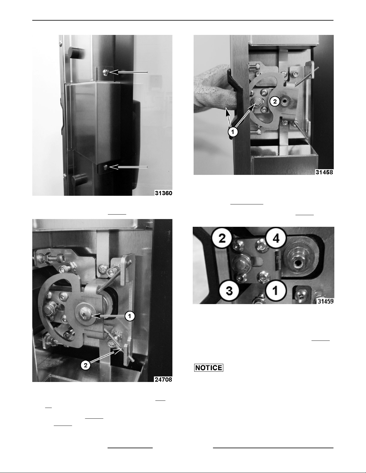
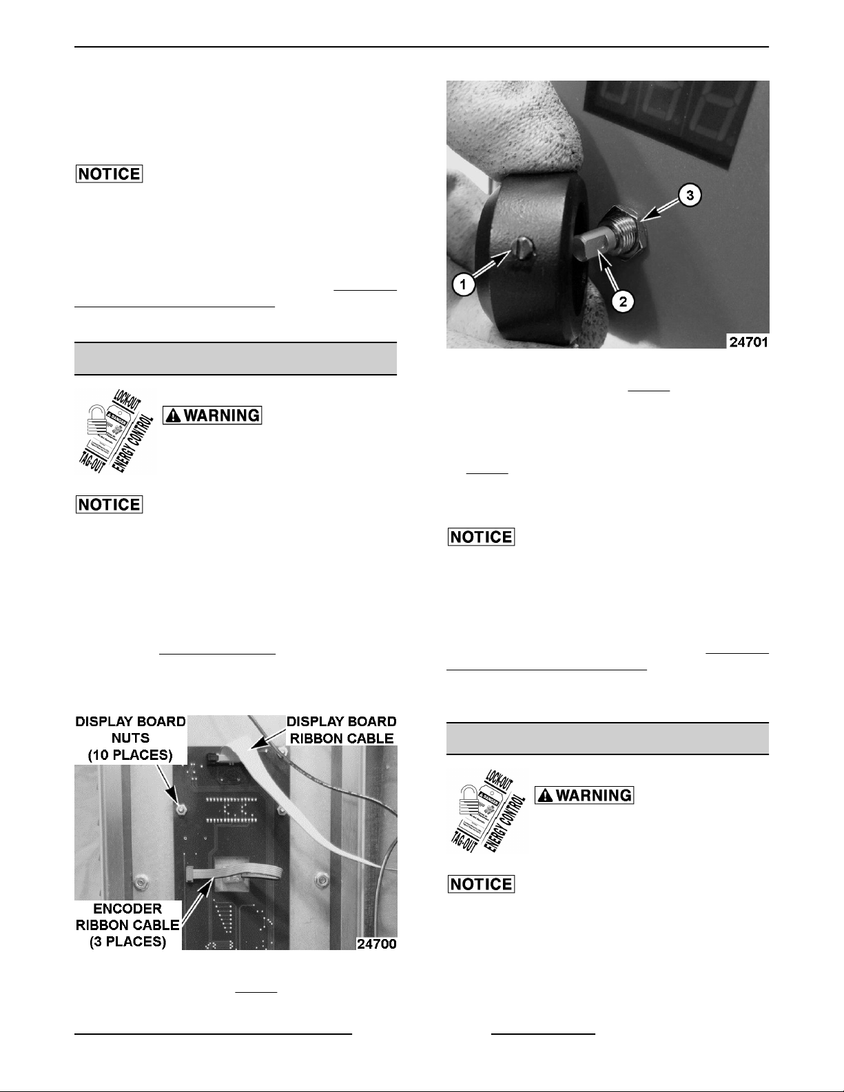
3. Remove cam screw (1, Fig. 14) and washer.
Latch Assembly
1. Remove DOOR CAM.
2. Remove four allen screws (1-4 in Fig. 16) on
plunger mechanism.
Fig. 16
3. Reverse procedure to install.
NOTE: When installing new plunger, tighten allen
screws in crisscross pattern as numbered in Fig. 16
torque to 24 in. lbs.
4. Check for proper operation.
Apply pressure to door latch to verify smooth
Fig. 14
4. Release torsion spring from lower slot (2, Fig.
14) in clamp bracket, then release top spring.
5. Press latch (1, Fig. 15) into door to remove cam
(2, Fig. 15).
F45491 Rev. B (0518) Page 16 of 119
movement.
Page 17
ABC Combi Gas Oven - REMOVAL AND REPLACEMENT OF PARTS
DOOR SWITCH
Disconnect the electrical power to
the machine and follow lockout /
tagout procedures.
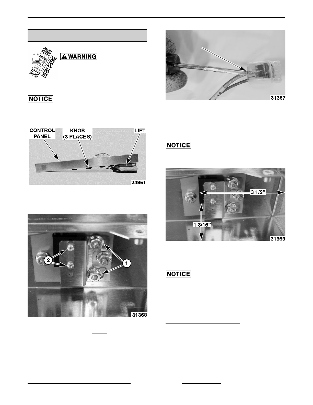
1. Remove CONTROL PANEL.
Do not place control panel on knobs. Doing so will
damage encoders. Lift one side of control panel up to
prevent knobs from touching surface.
Fig. 17
2. Remove back control panel.
3. Remove two lock nuts (1, Fig. 18).
Fig. 19
6. Reconnect wires to connector.
7. Install switch into bracket. Must measure 3 ½"
from bottom of control box and 1-3/16" as shown
in Fig. 20.
Measurements for switch placement are critical to
door switch operation.
Fig. 20
Fig. 18
4. Remove two screws (2, Fig. 18) to release switch
from bracket.
5. Insert screwdriver into switch wire connector and
push down on lower side to release wires.
Page 17 of 119 F45491 Rev. B (0518)
8. Install control panel back cover.
9. Install control panel to oven.
The door operation (latch, handle and sealing) can be
negatively affected any time the control panel has
been moved for servicing. Verify door latch alignment
with door by opening and closing door when Control
Panel is loosely mounted AND when securely
mounted. If door is not operational, perform DOOR TO
CONTROL PANEL ALIGNMENT.
10. Verify door switch operation.
Page 18
ABC Combi Gas Oven - REMOVAL AND REPLACEMENT OF PARTS
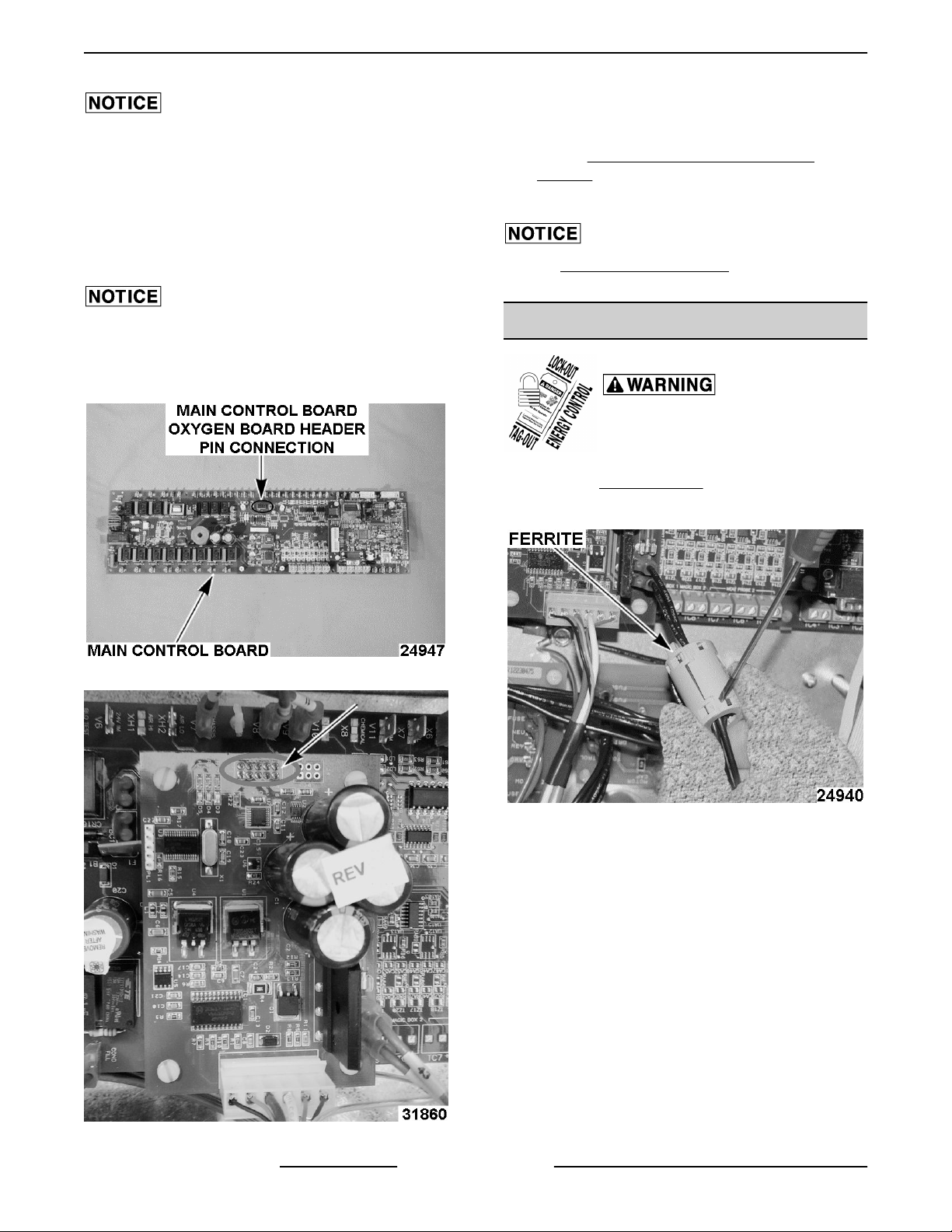
MAIN CONTROL BOARD
Certain components in this system are subject to
damage by electrostatic discharge (ESD) during field
repairs. An ESD kit is required to prevent damage. The
ESD kit must be used anytime the circuit board is
handled.
1. Check CONFIGURATION MODE (1972) - GAS
for customer's current parameter settings.
Document customer's parameter settings.
NOTE: This step can only be accomplished if main
control board is still operational.
NOTE: Oven hour counter (P18), water counter
values (P19, P20), and error log will start new, with
replacement main control board.
Disconnect the electrical power to
the machine and follow lockout /
tagout procedures.
2. Remove RIGHT PANEL.
3. Note and disconnect electrical connections from
main control board and oxygen sensor board.
NOTE: Oxygen sensor board is easier to install onto
main control board before installing main control
board.
2. Line up holes on new main control board with
nylon standoffs (x10).
3. Press board onto standoffs.
4. Follow diagram MAIN BOARD CONNECTIONS
to rewire replacement board.
5. Configure board to customer's preferred
parameter settings for P25, P26, and P29 in
configuration version. Refer to
CONFIGURATION MODE (1972) - GAS for
configuration settings.
6. Refer to CALIBRATE OXYGEN SENSOR
BOARD if oxygen board is being replaced.
7. Check for proper operation.
OXYGEN SENSOR
Disconnect the electrical power to
the machine and follow lockout /
tagout procedures.
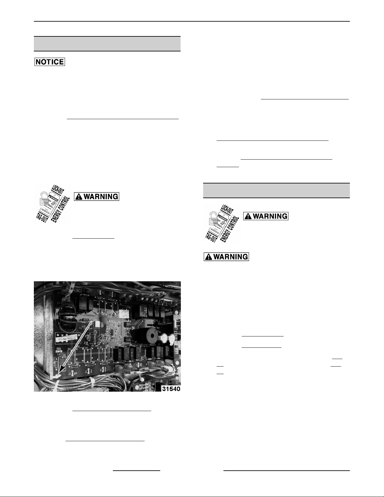
4. Squeeze nylon standoffs to release and remove
main control board.
Fig. 21
5. Remove OXYGEN SENSOR BOARD from main
control board.
Installation of Replacement Control Board
1. Install OXYGEN SENSOR BOARD onto
replacement main control board.
Oxygen sensor is very HOT. Use care when
servicing oxygen sensor.
NOTE: Remove power from unit before replacing
oxygen sensor. Having power to board when installing
sensor will cause damage oxygen sensor.
NOTE: Sensor can be damaged by water. Do not get
it wet.
1. Remove RIGHT PANEL.
2. Remove REAR PANEL.
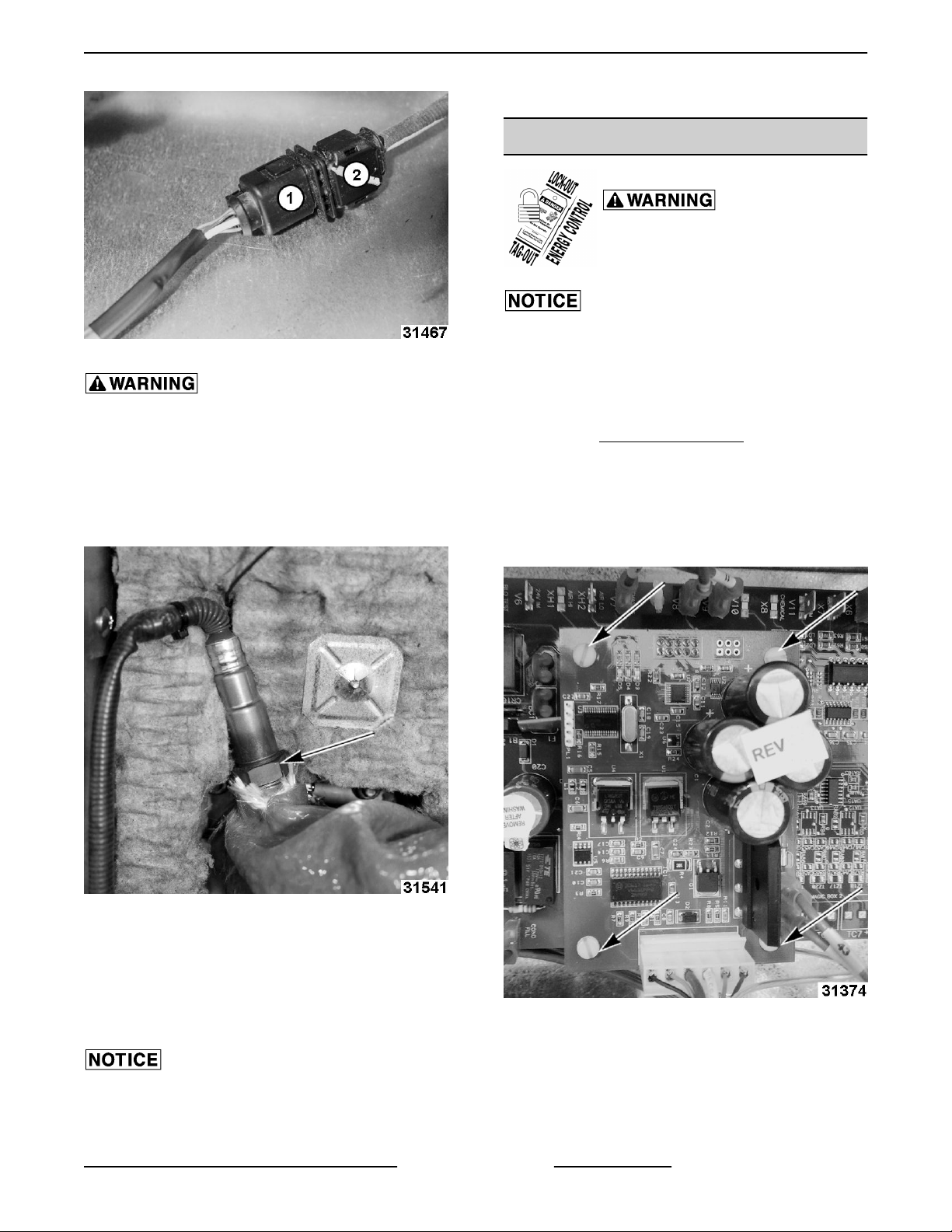
3. Disconnect main board TC cable plug (1, Fig.
22) from oxygen sensor cable at plug (2, Fig.
22).
NOTE: Do NOT disconnect cable from Oxygen
Sensor Board.
F45491 Rev. B (0518) Page 18 of 119
Page 19
ABC Combi Gas Oven - REMOVAL AND REPLACEMENT OF PARTS
Fig. 22
Allow oxygen sensor to cool completely before
removing. Sensor, when powered and operating,
is very HOT.
4. Remove all wire ties from oxygen sensor cable.
9. Check for proper operation.
OXYGEN SENSOR BOARD
Disconnect the electrical power to
the machine and follow lockout /
tagout procedures.
Certain components in this system are subject to
damage by electrostatic discharge (ESD) during field
repairs. An ESD kit is required to prevent damage. The
ESD kit must be used anytime the circuit board is
handled.
1. Remove RIGHT SIDE PANEL.
2. Note wire locations and remove connections
from oxygen sensor board.
5. After oxygen sensor has cooled, loosen hex and
carefully remove sensor from fitting.
Fig. 23
6. Reverse procedures to install.
3. Remove oxygen sensor board screws. Retain
screws for installation of replacement oxygen
sensor board.
7. When installing, route oxygen sensor cable as
previously installed.
NOTE: Inspect oxygen sensor extension cable for
damage and replace if necessary.
Oxygen sensor cables are sensitive to electrical noise
and must be routed away from other wires.
8. Power unit on.
Page 19 of 119 F45491 Rev. B (0518)
Fig. 24
Page 20
ABC Combi Gas Oven - REMOVAL AND REPLACEMENT OF PARTS
2. Secure using screws from replaced board.
Oxygen sensor board must be installed while unit is
unplugged. Failure to install while unit is
unplugged will cause permanent damage to oxygen
sensor board.
Installation of Oxygen Sensor Board.
1. Verify oxygen sensor board holes line up with the
main control board standoffs.
Verify electrical connection between main board and
oxygen board is secure by connecting 10-pin female
header on back side of oxygen board to 10-pin male
header located on main control board.
3. Power on unit.
4. Do not CALIBRATE OXYGEN SENSOR
BOARD except at high altitude.
5. Check for proper operation.
Refer to SERVICE MODE (1963) and perform oxygen
sensor test o1 through o5.
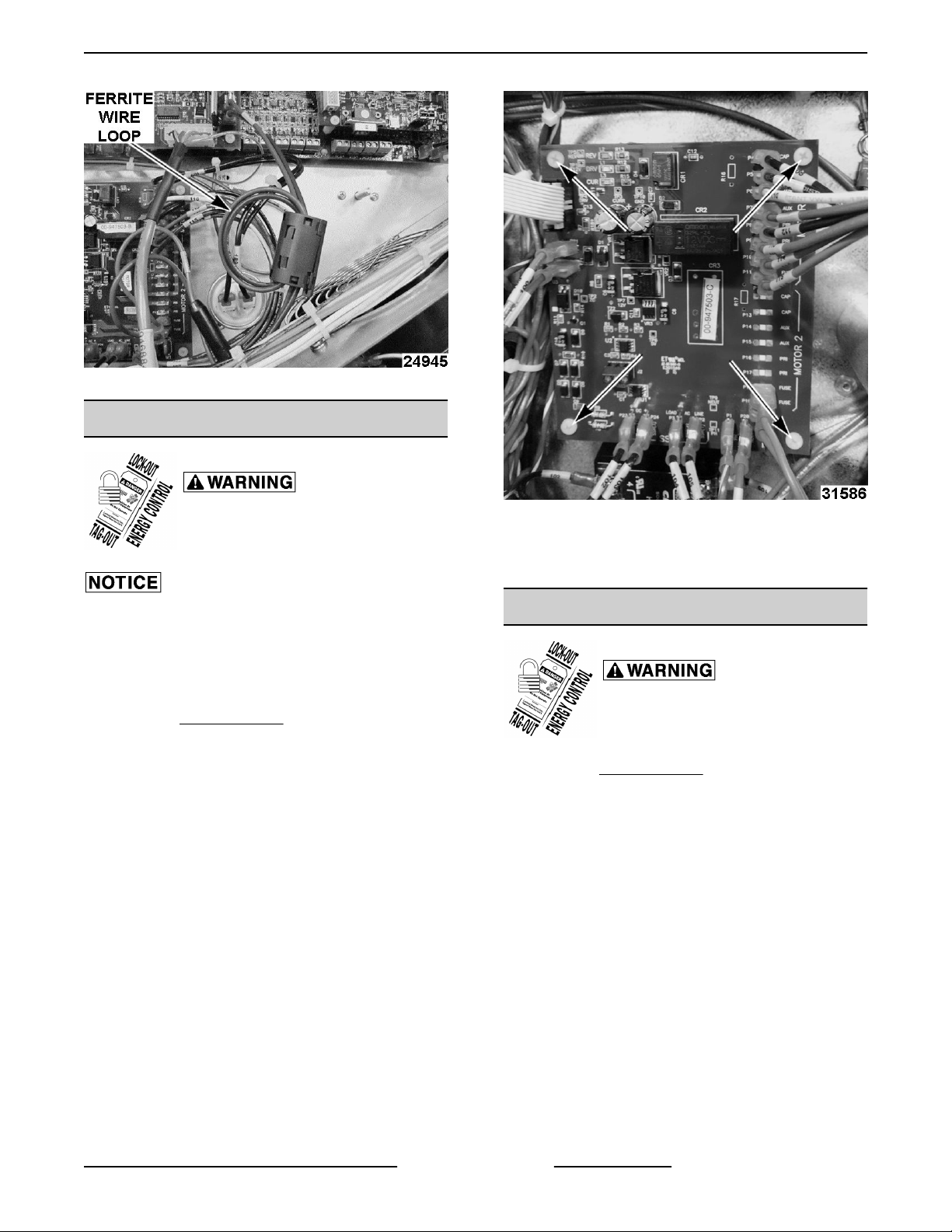
FERRITE
Disconnect the electrical power to
the machine and follow lockout /
tagout procedures.
1. Remove RIGHT PANEL.
2. Lift ferrite clip with flat screwdriver (two places).
Fig. 25
Fig. 27
3. Reverse procedures to install.
NOTE: Install ferrite approximately 3 inches from
oxygen sensor board.
NOTE: Loop ferrite wires around the ferrite to keep
ferrite in place.
Fig. 26
F45491 Rev. B (0518) Page 20 of 119
Page 21
ABC Combi Gas Oven - REMOVAL AND REPLACEMENT OF PARTS
Fig. 28
MOTOR CONTROL BOARD
Disconnect the electrical power to
the machine and follow lockout /
tagout procedures.
Certain components in this system are subject to
damage by electrostatic discharge (ESD) during field
repairs. An ESD kit is required to prevent damage. The
ESD kit must be used anytime the circuit board is
handled.
1. Remove RIGHT PANEL.
2. Note and disconnect electrical connections from
board.
3. Remove motor control board nylon screws.
Fig. 29
4. Reverse procedure to install.
5. Check for proper operation.
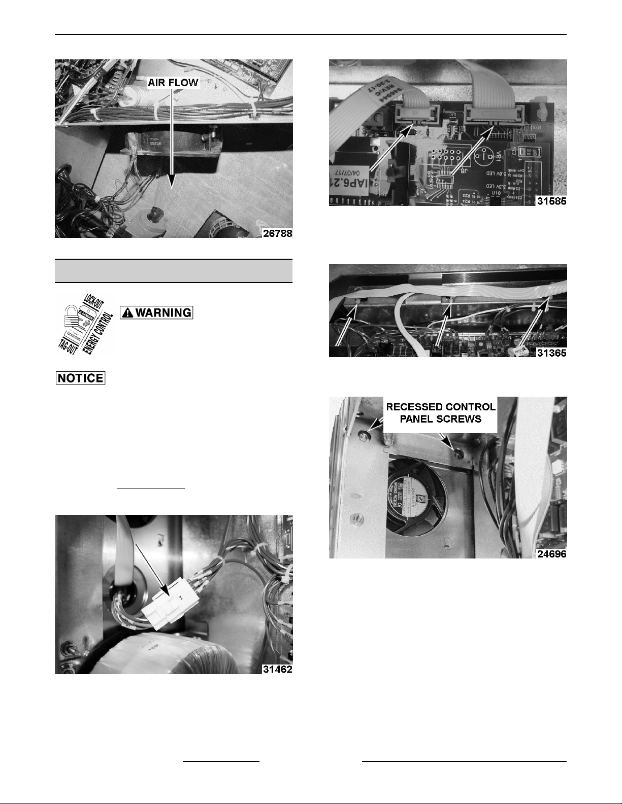
CONTROL BOX COOLING FAN
Disconnect the electrical power to
the machine and follow lockout /
tagout procedures.
1. Remove RIGHT PANEL.
2. Unplug two wires going to fan.
3. Remove screws securing fan to frame.
4. Check for proper air flow.
5. Reverse procedure to install.
Page 21 of 119 F45491 Rev. B (0518)
Page 22
ABC Combi Gas Oven - REMOVAL AND REPLACEMENT OF PARTS
Fig. 30
CONTROL PANEL
Fig. 32
4. Remove ribbon cable wire ties.
NOTE: Replace wire ties on install.
Disconnect the electrical power to
the machine and follow lockout /
tagout procedures.
Certain components in this system are subject to
damage by electrostatic discharge (ESD) during field
repairs. An ESD kit is required to prevent damage. The
ESD kit must be used anytime the circuit board is
handled.
Control Panel
1. Remove RIGHT PANEL.
2. Disconnect P1 connector.
Fig. 33
5. Remove recessed control panel screws.
Fig. 34
6. Lift control panel up off hooks.
NOTE: Carefully pull connector and ribbon cable
through hole when removing control panel.
Fig. 31
3. Disconnect motor and control board ribbon
cables.
F45491 Rev. B (0518) Page 22 of 119
Page 23

ABC Combi Gas Oven - REMOVAL AND REPLACEMENT OF PARTS
The door operation (latch, handle and sealing) can be
negatively affected any time the control panel has
been moved for servicing. Verify door latch alignment
with door by opening and closing door when Control
Panel is loosely mounted AND when securely
mounted. If door is not operational, perform
CONTROL PANEL ALIGNMENT.
NOTE: Motor control board ribbon cable will fit in J1
as well as J8, make sure it gets plugged into P1 on
Main board.
10. Verify proper operation.
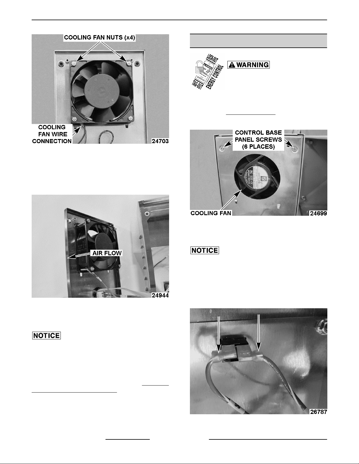
CONTROL PANEL COOLING FAN
Disconnect the electrical power to
the machine and follow lockout /
tagout procedures.
DOOR TO
Fig. 35
7. Place control panel on a clean, flat surface.
8. Place in secure location.
Do NOT place control panel flat on knobs. Doing so
will cause damage to encoders.
Fig. 36
9. Reverse procedures to install.
Certain components in this system are subject to
damage by electrostatic discharge (ESD) during field
repairs. An ESD kit is required to prevent damage. The
ESD kit must be used anytime the circuit board is
handled.
Display Board Fan
1. Remove CONTROL PANEL from unit.
2. Place control panel in a secure location.
3. Remove screws from back of control base panel.
Fig. 37
4. Disconnect cooling fan wire connection.
5. Remove cooling fan nuts.
Previous Production Shown
Page 23 of 119 F45491 Rev. B (0518)
Page 24
ABC Combi Gas Oven - REMOVAL AND REPLACEMENT OF PARTS
Fig. 38
6. Verify arrows are facing the correct direction
when installed.
NOTE: Air to exhaust out of control panel.
ON / OFF SWITCH
Disconnect the electrical power to
the machine and follow lockout /
tagout procedures.
On / Off Switch
1. Remove CONTROL PANEL from unit.
2. Remove screws from back of control base panel.
Previous Production Shown
Fig. 39
7. Reverse procedure to install.
8. Check for proper operation.
The door operation (latch, handle and sealing) can be
negatively affected any time the control panel has
been moved for servicing. Verify door latch alignment
with door by opening and closing door when Control
Panel is loosely mounted AND when securely
mounted. If door is not operational, perform DOOR TO
CONTROL PANEL ALIGNMENT.
Fig. 40
NOTE: Use care when removing back of control panel
cover. Wires are attached.
Certain components in this system are subject to
damage by electrostatic discharge (ESD) during field
repairs. An ESD kit is required to prevent damage. The
ESD kit must be used anytime the circuit board is
handled.
3. Disconnect On/Off switch wires.
F45491 Rev. B (0518) Page 24 of 119
Fig. 41
Page 25
ABC Combi Gas Oven - REMOVAL AND REPLACEMENT OF PARTS
4. Using a pair of channel locks, squeeze in the
sides and press the switch out the front of the
panel.
5. Reverse procedures to install.
The door operation (latch, handle and sealing) can be
negatively affected any time the control panel has
been moved for servicing. Verify door latch alignment
with door by opening and closing door when Control
Panel is loosely mounted AND when securely
mounted. If door is not operational, perform DOOR TO
CONTROL PANEL ALIGNMENT.
6. Check for proper operation.
KNOB & ENCODER
Disconnect the electrical power to
the machine and follow lockout /
tagout procedures.
Certain components in this system are subject to
damage by electrostatic discharge (ESD) during field
repairs. An ESD kit is required to prevent damage. The
ESD kit must be used anytime the circuit board is
handled.
Control Knob & Encoder
1. Remove CONTROL PANEL.
2. Place control panel in a secure location.
3. Disconnect encoder ribbon cables.
Fig. 43
5. Remove encoder nut (3,
encoder.
6. Reverse procedures to install.
NOTE: Tapped hole needs to be aligned with flat part
(2,
Fig. 43) of encoder. Align tab in control panel hole
needs to align with groove in encoder.
7. Check for proper operation.
The door operation (latch, handle and sealing) can be
negatively affected any time the control panel has
been moved for servicing. Verify door latch alignment
with door by opening and closing door when Control
Panel is loosely mounted AND when securely
mounted. If door is not operational, perform DOOR TO
CONTROL PANEL ALIGNMENT.
NOTE: Verify push button feature (ABCx-xxxxP
devices only) is operable after knob is installed.
Fig. 43) to remove
DISPLAY BOARD
Fig. 42
4. Loosen set screw (1, Fig. 43) in tapped hole on
knob.
Page 25 of 119 F45491 Rev. B (0518)
Disconnect the electrical power to
the machine and follow lockout /
tagout procedures.
Certain components in this system are subject to
damage by electrostatic discharge (ESD) during field
repairs. An ESD kit is required to prevent damage. The
ESD kit must be used anytime the circuit board is
handled.
Display Board
Page 26
ABC Combi Gas Oven - REMOVAL AND REPLACEMENT OF PARTS
1. Remove CONTROL PANEL.
2. Remove screws from back of control base panel.
Fig. 44
Use care when removing back of control panel cover.
Wires are attached.
Certain components in this system are subject to
damage by electrostatic discharge (ESD) during field
repairs. An ESD kit is required to prevent damage. The
ESD kit must be used anytime the circuit board is
handled.
3. Remove display board ribbon cable.
4. Remove encoder ribbon cables.
5. Remove display board nuts.
Fig. 46
7. Reverse procedures to install.
8. Check for proper operation.
The door operation (latch, handle and sealing) can be
negatively affected any time the control panel has
been moved for servicing. Verify door latch alignment
with door by opening and closing door when Control
Panel is loosely mounted AND when securely
mounted. If door is not operational, perform DOOR TO
CONTROL PANEL ALIGNMENT.
MEAT PROBE SOCKET
Disconnect the electrical power to
the machine and follow lockout /
tagout procedures.
1. Remove RIGHT SIDE PANEL.
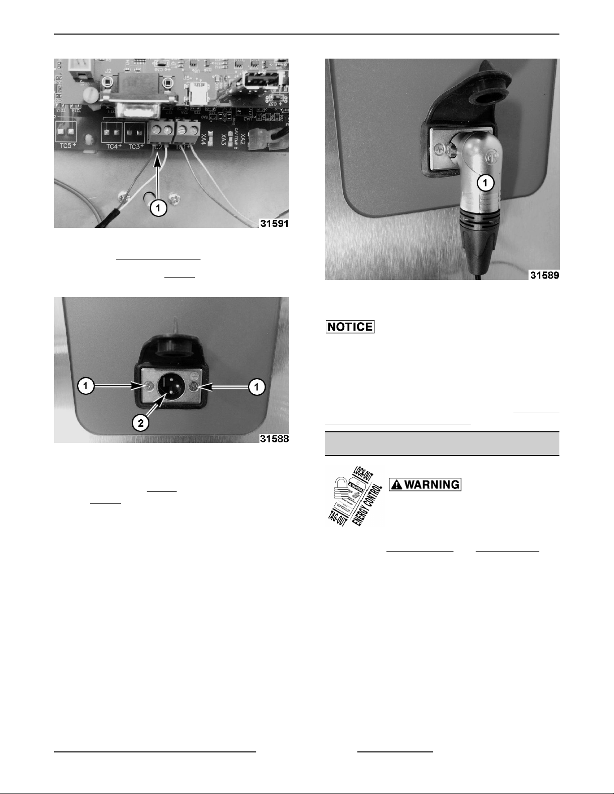
2. Disconnect probe socket from control board at
Fig. 45
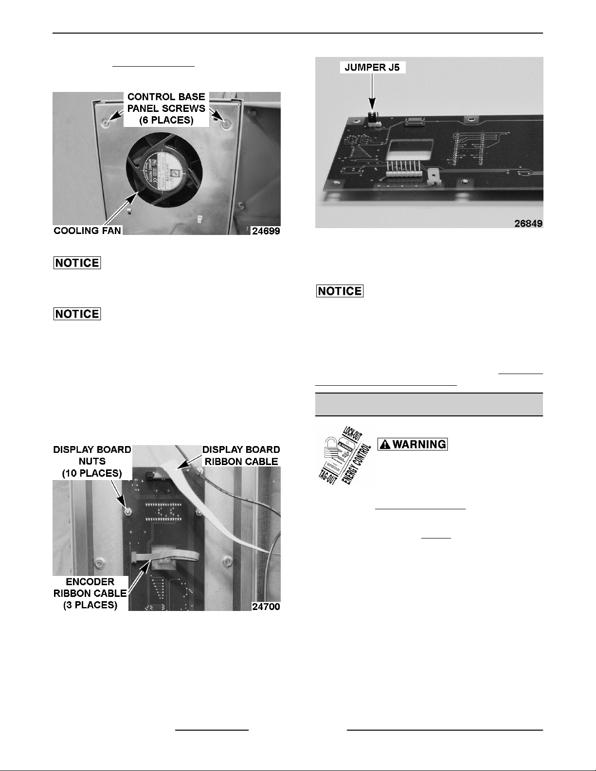
6. On new display board, verify jumper J5 on back
of display board is installed and on the correct
two pins. Two closest to edge of the board.)
F45491 Rev. B (0518) Page 26 of 119
TC2 connection (1, Fig. 47).
Page 27
ABC Combi Gas Oven - REMOVAL AND REPLACEMENT OF PARTS
Fig. 47
3. Remove CONTROL PANEL.
4. Remove screws (1, Fig. 48), nuts (from behind),
and probe socket from control panel.
Fig. 49
7. Check for proper operation.
Fig. 48
5. Reverse procedure to install.
6. Align prongs (2, Fig. 48) as shown so meat probe
(1, Fig. 49) plugs in with cord down.
The door operation (latch, handle and sealing) can be
negatively affected any time the control panel has
been moved for servicing. Verify door latch alignment
with door by opening and closing door when Control
Panel is loosely mounted AND when securely
mounted. If door is not operational, perform DOOR TO
CONTROL PANEL ALIGNMENT.
REAR COOLING FAN
Disconnect the electrical power to
the machine and follow lockout /
tagout procedures.
1. Remove RIGHT PANEL and REAR PANEL.
2. Remove two wires going to fan.
3. Remove nuts securing fan to frame.
Current Production Shown
Page 27 of 119 F45491 Rev. B (0518)
Page 28
ABC Combi Gas Oven - REMOVAL AND REPLACEMENT OF PARTS
HIGH-LIMIT THERMOSTAT
Disconnect the electrical power to
the machine and follow lockout /
tagout procedures.
1. Remove High-limit thermostat screws.
Fig. 50
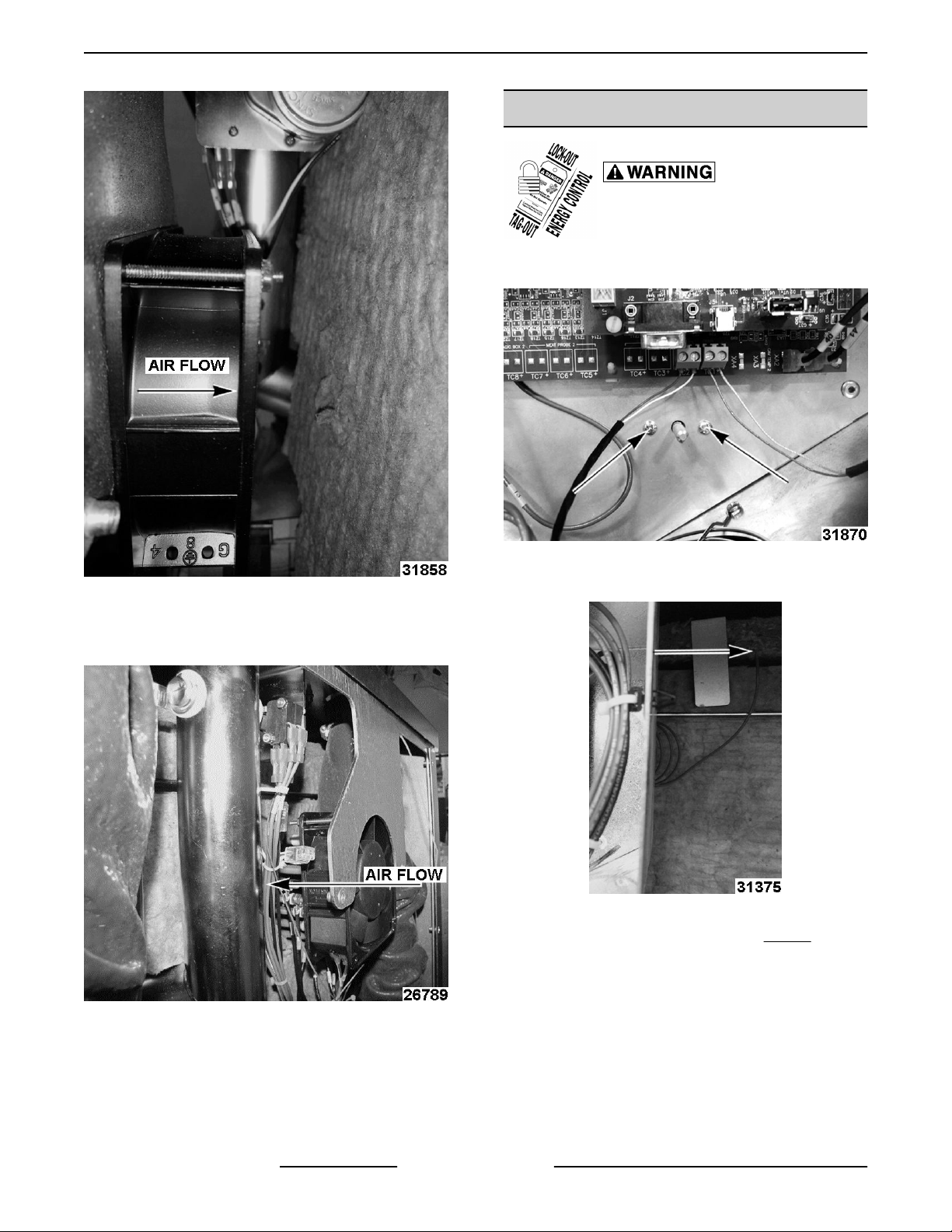
4. Check for proper air flow.
5. Reverse procedure to install.
Fig. 51
Fig. 52
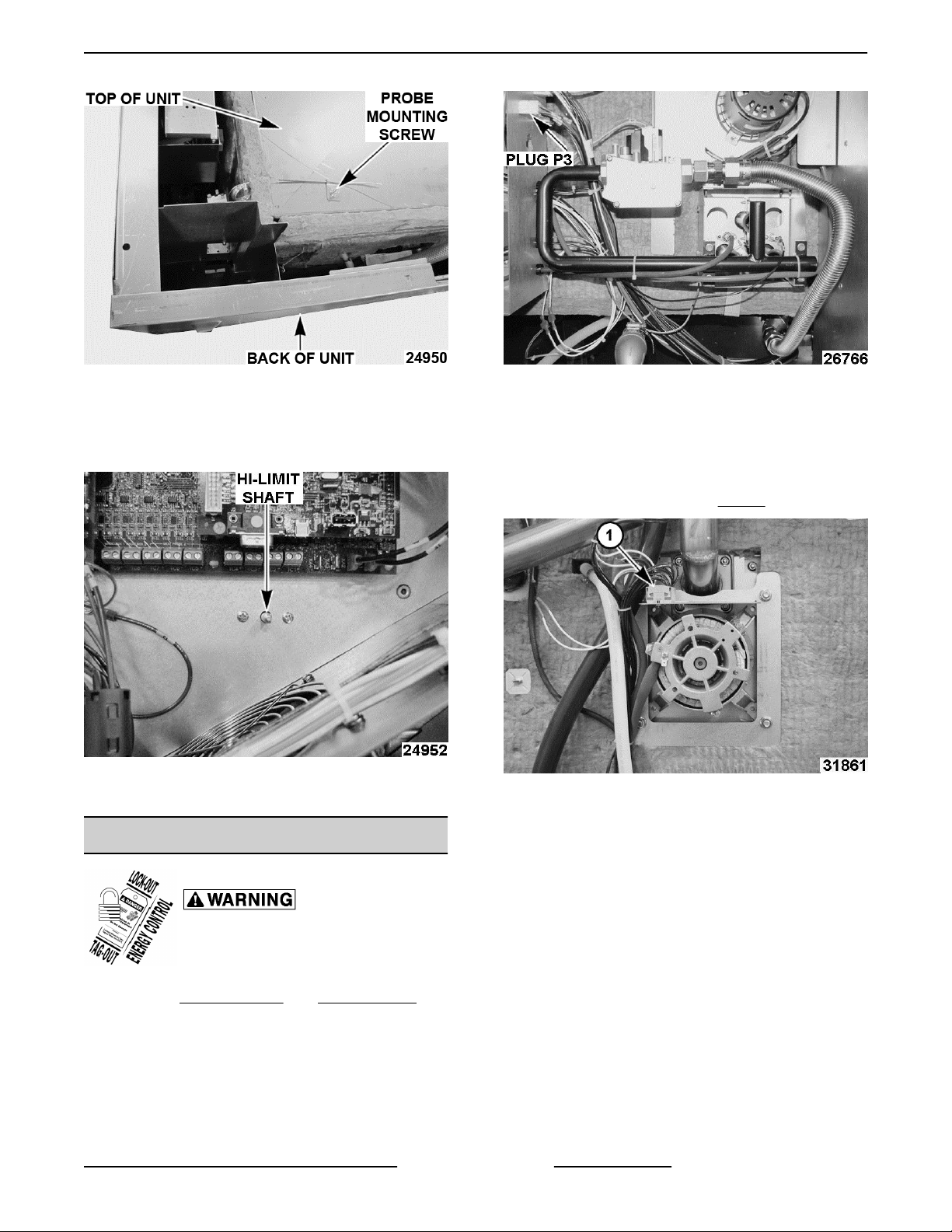
2. Remove High-limit thermostat probe.
Fig. 53
NOTE: Top panel removed in photo (Fig. 54) for
clarity. High-limit thermostat probe is located on top of
unit, under insulation.
NOTE: Turn Probe Mounting Screw quarter turn to
loosen. Do not remove probe mounting screw and
bracket.
F45491 Rev. B (0518) Page 28 of 119
Page 29
ABC Combi Gas Oven - REMOVAL AND REPLACEMENT OF PARTS
Fig. 54
3. Reverse procedures to install.
NOTE: When installing High-limit thermostat verify
high-limit shaft is turned clockwise until it stops.
Fig. 55
4. Check for proper operation.
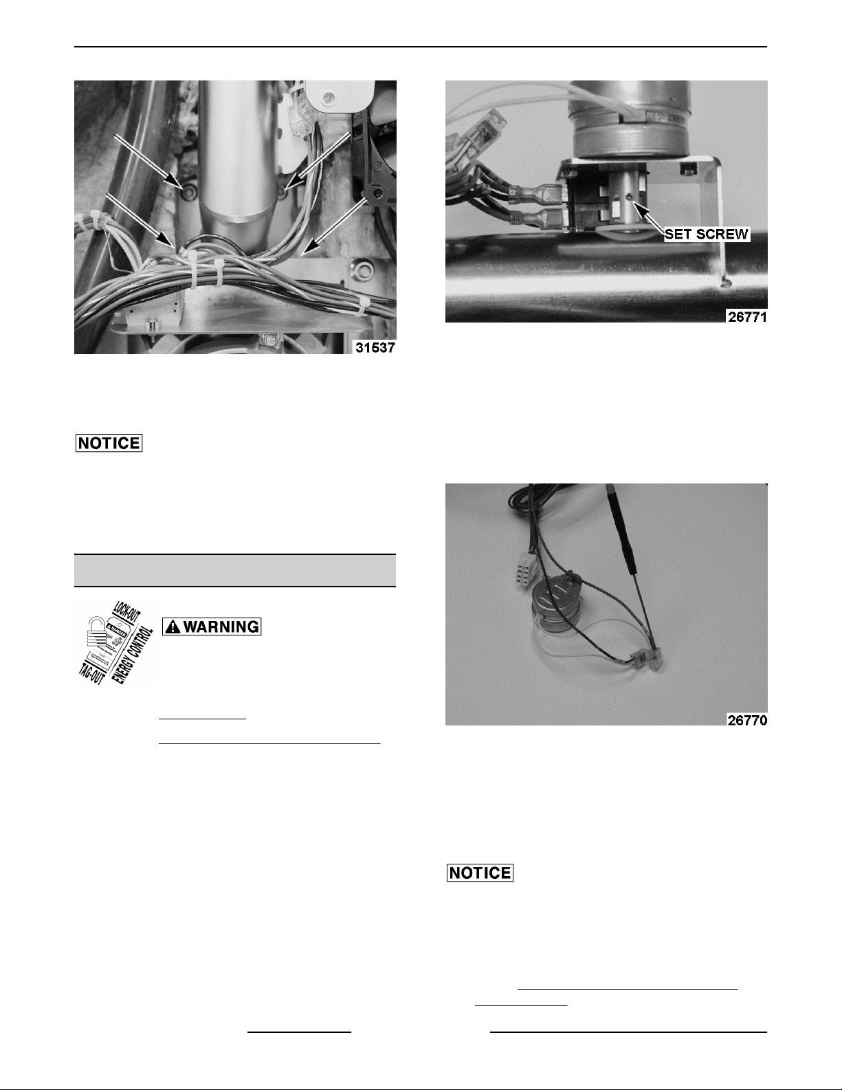
CAVITY INTAKE TUBE ASSEMBLY
Fig. 56
3. Cut cable ties as needed to free wiring harness
back to vent motor and switches.
NOTE: Note location of cable ties and wire routing.
Vent motor and switch cables have a strain relief.
4. Remove motor shroud (1, Fig. 57).
Fig. 57
5. Remove four nuts securing intake vent tube
assembly to back of cavity.
Disconnect the electrical power to
the machine and follow lockout /
tagout procedures.
1. Remove RIGHT PANEL and REAR PANEL.
2. On right side of unit, disconnect plug P3.
PREVIOUS GENERATION GAS OVEN
Page 29 of 119 F45491 Rev. B (0518)
Page 30
ABC Combi Gas Oven - REMOVAL AND REPLACEMENT OF PARTS
Fig. 59
Fig. 58
6. Replace parts as needed.
7. Reverse procedure to install.
Torque caity intake nuts to 24 in. lbs.
NOTE: There is a gasket between cavity intake tube
and the cavity. This gasket should be replaced.
8. Check for proper operation.
CAVITY VENT MOTOR
Disconnect the electrical power to
the machine and follow lockout /
tagout procedures.
1. Remove REAR PANEL.
2. Remove CAVITY INTAKE TUBE ASSEMBLY.
4. Loosen set screw.
5. Remove two screws securing vent motor to the
frame.
6. Pull motor free from assembly.
7. Insert blade of small screwdriver into wire nuts to
release motor wires.
Fig. 60
3. Rotate damper camshaft until set screw faces the
rear of the cavity intake tube assembly.
F45491 Rev. B (0518) Page 30 of 119
NOTE: A small straight blade screwdriver (jeweler
screwdriver) is needed.
NOTE: If a small screwdriver is not available, cutting
the wires and using a standard wire nut is acceptable.
8. Reverse procedure to install.
When inserting new motor, ensure flat side of motor
shaft faces the set screw.
NOTE: Note location of cable ties and wire routing.
Vent motor and switch cables have a strain relief.
9. Check CAVITY VENT SWITCH TEST AND
ADJUSTMENT.
Page 31

ABC Combi Gas Oven - REMOVAL AND REPLACEMENT OF PARTS
10. Check for proper operation.
CAVITY VENT SWITCHES
Disconnect the electrical power to
the machine and follow lockout /
tagout procedures.
1. Remove RIGHT PANEL and REAR PANEL.
2. Remove wires going to cavity vent switches.
Fig. 63
8. Perform CAVITY VENT SWITCH TEST AND
ADJUSTMENT.
TRANSFORMER
Fig. 61
3. Remove screws securing switches to frame.
Disconnect the electrical power to
the machine and follow lockout /
tagout procedures.
1. Remove RIGHT PANEL and REAR PANEL.
2. Disconnect plugs P7 (1, Fig. 64) and P8 (2, Fig.
64) going to transformer (3, Fig. 64).
Fig. 62
4. Remove top screw and remove switches from
frame.
5. Replace switch or switches as needed.
6. Reverse procedure to install.
7. Attach wires to switches.
NOTE: Note location of cable ties and wire routing.
Vent motor and switch cables have a strain relief.
Page 31 of 119 F45491 Rev. B (0518)
Page 32

ABC Combi Gas Oven - REMOVAL AND REPLACEMENT OF PARTS
Fig. 66
Transformer weighs 12.5 pounds and has a strong
magnetic pull to the frame of oven.
5. Slide transformer off studs and down to the
bottom of the oven.
Fig. 64
3. Remove two nuts on left hand side of transformer
bracket.
Fig. 65
4. Remove nut on the right hand side of transformer
bracket.
Fig. 67
6. Remove transformer and bracket from oven.
7. Remove nut and both washers securing
transformer to bracket.
F45491 Rev. B (0518) Page 32 of 119
Fig. 68
Page 33

ABC Combi Gas Oven - REMOVAL AND REPLACEMENT OF PARTS
8. Replace transformer.
9. Tighten nyloc nut to 75 in. lbs. to ensure
transformer does not rotate loose.
10. Reverse procedure to install.
TEMPERATURE SENSOR (RTD1)
Disconnect the electrical power to
the machine and follow lockout /
tagout procedures.
1. Remove RIGHT PANEL.
2. Remove REAR PANEL.
3. Remove all RTD wire ties.
4. Remove black wire from TB2-3 and red wire from
TB2-4.
NOTE: Insert small screwdriver in square next to the
wire to release the wire from terminal block.
B. Pull upper insulation clip out and slide over
out of the way.
C. Spin square insulation clip holding outer
layer.
D. Carefully remove outer layer of insulation
and set aside for reinstalling.
E. Cut inner layer of insulation.
F. Spin square insulation clip holding inner
layer.
G. Carefully remove inner layer of insulation
and set aside for reinstalling.
7. Remove both RTD nuts.
Fig. 69
5. Remove OXYGEN SENSOR.
6. Remove insulation.
Fig. 70
A. Cut outer layer of insulation.
Fig. 71
8. Remove temperature sensor RTD1 and gasket
from unit.
9. Clean mounting surface.
10. Reverse procedure to install.
RTD wiring should exit straight out of insulation
through special slot cut out in insulation and not
pressed against oven cavity. Do not wire tie.
Verify insulation is tucked underneath upper insulation
clip. Must replace insulation to prevent oven from
overheating.
NOTE: Torque probe nuts at 10 in. lbs.
11. Check for proper operation.
Page 33 of 119 F45491 Rev. B (0518)
Page 34

ABC Combi Gas Oven - REMOVAL AND REPLACEMENT OF PARTS
DRAIN WATER CONDENSATE
VALVE
Disconnect the electrical power to
the machine and follow lockout /
tagout procedures.
1. Remove RIGHT PANEL and REAR PANEL.
2. Remove two screws securing valve to utility
panel.
7. Check for proper operation.
DRAIN WATER THERMOCOUPLE
Disconnect the electrical power to
the machine and follow lockout /
tagout procedures.
1. Remove RIGHT PANEL.
2. Loosen screws for terminal TC1 and remove
wires.
Fig. 72
3. Remove two wires going to valve.
4. Loosen hose clamp and pull valve free of hose.
Fig. 73
5. Replace valve.
Fig. 74
3. Cut cable ties securing wires going to drain water
thermocouple.
4. Loosen fitting that goes to drain.
1st Generation Production
Fig. 75
2nd Generation Production
6. Reverse procedure to install.
F45491 Rev. B (0518) Page 34 of 119
Page 35

ABC Combi Gas Oven - REMOVAL AND REPLACEMENT OF PARTS
8. Refer to CONFIGURATION MODE (1972) GAS to check parameter P25, P26. based on
drain type.
HUMIDITY VALVE
Disconnect the electrical power to
the machine and follow lockout /
tagout procedures.
1. Remove RIGHT PANEL and REAR PANEL.
Fig. 76
5. Pull thermocouple from housing.
Fig. 77
6. Replace thermocouple ensuring the
thermpcouple is set to .800.
Thermocouple shown outside machine for clarity.
Dimension of .800 should be met when thermocouple
is installed.
2. Remove screws securing humidity valve to utility
panel.
Fig. 79
NOTE: The humidity valve is a double valve.
3. Remove two wires going to drain water
condensate valve.
NOTE: This makes it easier to pull the humidity valve
out from behind the utility panel.
Fig. 78
7. Reverse procedure to install.
4. Remove the four wires going to humidity valve.
NOTE: Make sure to note which wire goes to which
terminal.
Page 35 of 119 F45491 Rev. B (0518)
Page 36

ABC Combi Gas Oven - REMOVAL AND REPLACEMENT OF PARTS
Fig. 80
5. Loosen the two hose clamps securing the valve
and free the valve from the two hoses.
Fig. 82
2. Remove left and right rack guides (1, Fig. 83).
Fig. 81
6. Replace valve.
Correct valve orientation prevents a water "stuck on"
condition. Verify water valve tubes are on top and
electrical connections are on bottom when installing.
7. Reverse procedure to install.
CONVECTION FAN BAFFLE
The oven and its parts are hot. Use care when
operating, cleaning or servicing the oven.
1. Remove all oven racks (1, Fig. 82).
Fig. 83
3. Lift baffle (1, Fig. 84) up off bottom baffle support
guides (Fig. 85).
4. Lift baffle over bottom rack guide hangers (2, Fig.
84).
5. Lift baffle up off top baffle hangers (Fig. 85).
Fig. 84
F45491 Rev. B (0518) Page 36 of 119
Page 37

ABC Combi Gas Oven - REMOVAL AND REPLACEMENT OF PARTS
6. Pull towards front of oven to remove.
7. Reverse procedures to install.
Verify convection fan baffle is hooked on top panel and
supported behind bottom baffle support guides.
Fig. 85
CONVECTION FAN MOTOR
Certain components in this system are subject to
damage by electrostatic discharge (ESD) during field
repairs. An ESD kit is required to prevent damage. The
ESD kit must be used anytime the circuit board is
handled.
Fig. 86
4. Note and disconnect motor wires (1, Fig. 86).
Convection Fan Terminal Block (TB2)
Connection Call-outs
A TB Block Number
White 10
Blue 9
Black 8
Red 7
Brown 6
Brown 5
Any wire ties removed during removal must be
replaced during installation.
Disconnect the electrical power to
the machine and follow lockout /
tagout procedures.
NOTE: When using gear puller to remove convection
fan, do not use factory stainless steel cap screw or
damage to the screw head may occur. Use a spare
M6 cap screw as listed under TOOLS.
Convection Fan
1. Remove RIGHT PANEL.
2. Remove REAR PANEL.
3. Remove humidity hose clamp (3, Fig. 86).
NOTE: Insulation removed from for clarity.
Page 37 of 119 F45491 Rev. B (0518)
5. Remove nuts, shroud and spacers if they exist (2,
Fig. 86).
Do not remove motor mounting nuts at this time.
6. Remove CONVECTION FAN BAFFLE.
7. Remove humidity cavity nozzle nuts (Fig. 87) to
rotate nozzle for clearance.
NOTE: Replace nozzle gasket if necessary.
Page 38

ABC Combi Gas Oven - REMOVAL AND REPLACEMENT OF PARTS
Fig. 87
8. Remove socket head cap screw.
NOTE: May need to apply heat for removal.
Fig. 88
9. Remove atomizer bolt (Fig. 88).
NOTE: Atomizer bolt is a left-handed bolt.
NOTE: May need to apply heat for removal.
Fig. 89
13. Install gear puller.
14. Tighten gear puller to separate convection fan
from motor shaft.
NOTE: Applying heat uniformly to groove in
convection fan will assist with separation of fan and
motor shaft.
15. Remove motor mounting nuts.
16. Reverse procedure to install.
NOTE: Verify motor wire orientation before installing.
10. Remove water atomizer.
11. Thread atomizer bolt into fan motor shaft. Leave
approximately 1/8" space between hex head on
atomizer bolt and fan hub.
12. Insert spare M6 cap screw into fan motor shaft.
Hand tighten only.
Apply Loctite™ 272 to all torqued threads.
17. Set specific torques when installing.
F45491 Rev. B (0518) Page 38 of 119
Fig. 90
Page 39

ABC Combi Gas Oven - REMOVAL AND REPLACEMENT OF PARTS
• Torque motor mount nuts to 240 in. lbs.
• Torque atomizer bolt to 350 in. lbs.
• Torque atomizer socket head cap screw to
75 in. lbs.
• Verify atomizer nozzle is aligned with center
of atomizer blade locking screw and torque
nuts to 75 in. lbs.
NOTE: Tighten atomizer nozzle clamp after baffle,
rack guides and racks are installed.
18. Check for proper operation.
GAS VALVE
Disconnect the electrical power to
the machine and follow lockout /
tagout procedures.
Certain components in this system are subject to
damage by electrostatic discharge (ESD) during field
repairs. An ESD kit is required to prevent damage. The
ESD kit must be used anytime the circuit board is
handled.
NOTE: Make sure the switch on gas valve is turned
on.
Fig. 92
9. Check for proper operation.
IGNITOR
Disconnect the electrical power to
the machine and follow lockout /
tagout procedures.
1. Remove RIGHT PANEL.
2. Remove wires from gas valve.
3. Remove gas line from gas valve.
4. Remove high voltage ignitor cable from ignitor.
5. Remove flame sensor wire from flame sensor.
6. Remove manifold screws from burner.
7. Remove gas valve from manifold.
Fig. 91
Ignitor Removal
1. Remove RIGHT PANEL.
2. Disconnect high voltage cable from ignitor.
Fig. 93
3. Remove ignitor screw.
4. Pull ignitor to remove.
5. Reverse procedures to install.
8. Reverse procedures to install.
Page 39 of 119 F45491 Rev. B (0518)
Page 40

ABC Combi Gas Oven - REMOVAL AND REPLACEMENT OF PARTS
NOTE: Verify high voltage cable is routed separately
from flame sensor cable (wire 206) and ground wire
(wire 205).
Fig. 95
5. Reverse procedures to install.
NOTE: Verify high voltage cable is routed separately
from flame sensor cable (wire 206) and ground wire
(wire 205).
Fig. 94
6. Check for proper operation.
FLAME SENSOR
Disconnect the electrical power to
the machine and follow lockout /
tagout procedures.
Flame Sensor Removal
1. Remove RIGHT PANEL.
2. Disconnect flame sensor cable (wire 206) from
flame sensor.
3. Remove flame sensor screw.
4. Pull flame sensor to remove.
Fig. 96
6. Check for proper operation.
INDUCER BLOWER
1. Remove RIGHT PANEL.
F45491 Rev. B (0518) Page 40 of 119
Disconnect the electrical power to
the machine and follow lockout /
tagout procedures.
Page 41

ABC Combi Gas Oven - REMOVAL AND REPLACEMENT OF PARTS
2. Remove REAR PANEL.
3. Disconnect inducer blower wires.
INDUCER
BLOWER
BLACK 211 (Black)
WHITE 213 (White)
RED 212 (Red)
4. Remove motor shroud screws.
5. Lift up and towards front of unit to remove.
WIRE HARNESS
Fig. 99
8. Push gas flue (1, Fig. 100) back.
Fig. 97
6. Remove air pressure hose.
Fig. 98
Fig. 100
9. Remove inducer blower assembly mounting
nuts.
7. Remove gas flue screws (1, Fig. 99).
Fig. 101
Page 41 of 119 F45491 Rev. B (0518)
Page 42

ABC Combi Gas Oven - REMOVAL AND REPLACEMENT OF PARTS
10. Pull to remove inducer blower assembly.
11. Remove any excess inducer blower seal and
clean surface before replacing seal.
12. Reverse procedures to install.
13. Check for proper operation.
HEAT EXCHANGER ASSEMBLY
Disconnect the electrical power to
the machine and follow lockout /
tagout procedures.
1. Remove RIGHT PANEL.
2. Remove REAR PANEL.
3. Remove gas flue screws (1, Fig. 102) from
blower.
Fig. 102
4. Push gas flue (1, Fig. 103) back.
Fig. 104
6. Remove gas valve assembly mounting nuts.
Fig. 105
7. Remove inducer blower assembly mounting
nuts.
Fig. 103
5. Remove ignitor wire, flame sense wire, and air
pressure hose (Fig. 104).
F45491 Rev. B (0518) Page 42 of 119
Page 43

ABC Combi Gas Oven - REMOVAL AND REPLACEMENT OF PARTS
Fig. 108
9. Insert 2x4 board between heat exchanger and
bottom of cavity.
Fig. 106
8. Remove burner assembly mounting nuts.
Right Side
Fig. 107
Left Side
Fig. 109
10. Remove mounting plate nuts.
Fig. 110
11. Pull to remove heat exchanger from inside oven
cavity. Remove any remaining gasket and clean
surface.
NOTE: Check heat exchanger gasket for proper
sealing.
12. Replace heat exchanger gasket.
13. Reverse procedure to install.
Page 43 of 119 F45491 Rev. B (0518)
Page 44

ABC Combi Gas Oven - REMOVAL AND REPLACEMENT OF PARTS
14. Torque nuts to 75 in. lbs.
15. Check for proper operation.
DRAFT INDUCER PRESSURE
SWITCH
Disconnect the electrical power to
the machine and follow lockout /
tagout procedures.
1. Remove RIGHT PANEL.
2. Remove leads from pressure switch.
Fig. 112
3. Remove wires.
Fig. 111
3. Remove tube from pressure switch.
4. Remove screws and nuts securing pressure
switch.
5. Reverse procedure to install.
IGNITION MODULE
Ignition
Module
S1 Remote Flame Sensor 206
GND System Ground 205
V2 Valve Ground 207
24VAC 24 VAC Supply 209
L1 120 VAC Input (hot) 203
IND Inducer Blower (output) 204
NC
V1 Valve Power (Output) 208
PSW Pressure Switch Input 201
TH / W Thermostat Input 200
FC+
FC-
4. Remove ignition module screws and nuts.
5. Reverse procedure to install.
Description
Alarm (normally closed
contact)
Flame Current Test
Pins
Wire
Number
225
None
Disconnect the electrical power to
the machine and follow lockout /
tagout procedures.
1. Remove RIGHT PANEL.
2. Remove high voltage cable.
F45491 Rev. B (0518) Page 44 of 119
Page 45

ABC Combi Gas Oven - REMOVAL AND REPLACEMENT OF PARTS
Fig. 113
NOTE: Verify high voltage cable is routed separately
from flame sensor cable (wire 206) and ground wire
(wire 205).
Fig. 114
6. Check for proper operation.
Page 45 of 119 F45491 Rev. B (0518)
Page 46

ABC Combi Gas Oven - SERVICE PROCEDURES AND ADJUSTMENTS
SERVICE PROCEDURES AND ADJUSTMENTS
Certain procedures in this section require electrical test or measurements while power is
applied to the machine. Exercise extreme caution at all times and follow Arc Flash procedures.
If test points are not easily accessible, disconnect power and follow Lockout/Tagout
procedures, attach test equipment and reapply power to test.
CONFIGURATION MODE (1972) - GAS
Log Into Configuration Mode 1972
1. Check with customer to verify settings have not been altered from factory settings.
2. Turn unit on.
NOTE: Oven must have no temp set to enter configuration.
3. Turn Timer knob counterclockwise until Timer display shows "set".
4. Turn Humidity knob counterclockwise until Humidity display shows "PAS".
A. Timer display will show "2000".
5. Turn Timer display counterclockwise to 1972.
A. Timer display will flash "1972".
B. Timer and Humidity display will flash twice.
C. Humidity display changes from "PAS" to "CFg" when logging into Configuration Mode.
D. Temperature Display will go to P0, which is the first configuration setting.
To review / change Configuration Mode 1972 settings
1. Turn the Temperature knob clockwise one step at a time, to go to the next configuration setting.
NOTE: Currently addresses P22, P30, and P31 are blank.
2. Presently P35 is the last address, the counter will continue to go higher, but the Time display and the Humidity
display will be blank.
3. Turn the Humidity Knob to change the values as needed.
4. Refer to: "Configuration Mode (1972) Settings" chart below for options.
Logging out of Configuration Mode 1972
1. Turn Temperature knob counterclockwise until "---" displayed.
F45491 Rev. B (0518) Page 46 of 119
Page 47

Temp.
Display
("---")
ABC Combi Gas Oven - SERVICE PROCEDURES AND ADJUSTMENTS
Configuration Mode (1972) Settings
Time Display
Description
("----")
Humidity Display
("---")
17
P0 Current firmware code revision (Month, day, year).
P1 Set temperature to Fahrenheit or Celsius. UnIt F or C
Temperature knob increments.
P2
P3
P4
P5
Temperature increment can be adjusted by 1, 5, or 10
degrees.
Humidity knob increments.
Humidity can be adjusted by 1 or 10 percent increments.
Custom Operator Interface
Factory Default UI Setting FACt
Custom UI Setting CUSt
NOTE: Operator can flip between P4 FACt and P4 CUSt. Custom settings will
be remembered.
NOTE: Only when P4 is set to custom can settings in P5 and P6 be configured.
Define Temperature Selection in UI
NOTE: Only when P4 is set to custom can settings in P5
and P6 be configured.
(Month: 04, Day: 24)
(Indicates customer
settings are currently
0424
tInC 1, 5, 10, 25
HInC 1 and 10
FACt
CUSt
loaded.)
(Year: 2017)
Letter after number. =
Revision within a
date.
Turn Hum knob
between Factory
(FACt) and Custom
(CUSt)
SEt
Turn knob to edit
custom settings.
oN
TIP: Select “ALL on”
ALL
Page 47 of 119 F45491 Rev. B (0518)
to begin customizing
if minimal changes
needed to FACt
settings.
Page 48

Temp.
Display
("---")
ABC Combi Gas Oven - SERVICE PROCEDURES AND ADJUSTMENTS
Configuration Mode (1972) Settings
Time Display
Description
("----")
Humidity Display
("---")
oFF
80 (min)
... 482 (max)
Turn Timer knob
through temperature
choices.
Define Humidity Selection in UI
NOTE: Only when P4 is set to custom can settings in P5
and P6 be configured.
80 (F)
P6
482(F)
Turn Timer knob
through temperature
choices.
NOTE: The following is an example of customizing the P4 through P6 settings.
P4
P5
P6
P4 set to CUSt Example
1. Toggle Hum knob to select CUSt settings.
2. Turn Temperature knob to P5.
3. Toggle Hum knob oFF.
4. Scroll timer knob to temperature of 212.
5. Toggle humidity knob to on.
6. Scroll timer knob to 325.
7. Toggle humidity knob to on.
8. Turn Temperature knob to P6.
9. Scroll timer knob to 325.
212(F) on
325(F) on
212(F)
ALL
.
.
.
FACt
.
.
.
CUSt
ALL oFF
TIP: Select “ALL oFF”
if you want to start
customizing from
scratch.
oFF / on
Hum knob can be
toggled to change
individual
temperature on or off.
90 (% humidity)
0 (%)
Hum knob can be
used to change
humidity mapping to
selected
temperature.
100(%)
.
.
.
10. Toggle knob to 0%
F45491 Rev. B (0518) Page 48 of 119
325(F)
0(%)
Page 49

Temp.
Display
("---")
11. At completion, user interface is customized so user can only select 212F @ 100% or 325F @ 0%
End of example.
P7
Allows users to manual adjust humidity settings during
operation.
Oven Buzzer
ABC Combi Gas Oven - SERVICE PROCEDURES AND ADJUSTMENTS
Configuration Mode (1972) Settings
Time Display
Description
("----")
HAdJ on / oFF
Humidity Display
("---")
P8
P9
P10
P11
P12
ON - Buzzer stops after 5 seconds.
OFF - Buzzer turns on until door is opened or timer is
turned off.
Door Lights
ON - Door lights flash at end of timer countdown.
OFF - Door lights do not flash at end of countdown.
Batch Timer.
Timer recalls last operated value when door is open and
closed after buzzer. User does not need to reset timer.
For example, User removes a batch of fries from oven
and puts in a second batch of fries.
Clean reminder.
"CLn good bYE" shown when on/off switch is toggled off.
Convection Fan Speed.
• Non-adjustable: units without probe
or units 8-11-14 FIRMWARE and prior.
• Units with Probe only (adjustable).
• 1400+ RPMs
b 5 on / oFF
FLSH on / oFF
trCL on / oFF
CLn on / oFF
F3 7
Turn Timer Knob
F2 4-6
Turn Timer Knob
• 700-900-1250 RPMs
• 525-700-900 RPMs
NOTE: Speed selected for F1 must always be below F2.
P13 Convection Fan Breaking Speed. (not adjustable) F br 5
Reversing fan timing.
P14
P15
Number of minutes cavity fan turns before breaking and
turning in opposite direction.
Define maximum temperature knob setting in UI.
Maximum temperature that can be set by user. Minimum
setting limited by P16.
Page 49 of 119 F45491 Rev. B (0518)
F1 3-5
FrEU Off, 2, 3, 4, 5
80 thru 482
t_HI
increments of 1,
(450default).
Page 50

Temp.
Display
("---")
P16
ABC Combi Gas Oven - SERVICE PROCEDURES AND ADJUSTMENTS
Configuration Mode (1972) Settings
Description
Define minimum temperature knob setting in UI.
Minimum temperature that can be set by user. Maximum
setting limited by P15.
NOTE: Must be less than P15.
NOTE: Settings at P15 and P16 are only in effect if P4
is set to FACt.
Cavity Automatic Steam Reduction: Reduces the cavity's
steam build up before end of timed cook. Vent intake is
opened "selected" seconds before end of timer
countdown.
Time Display
("----")
t_Lo
Humidity Display
("---")
80 thru 482
increments of 1.
P17
P18
P19
P20
NOTE: Steam reduction is not engaged mid-cook or
during a "non-timed" cook when door opened.
Example: P17 = 30 seconds (default). As the cook time
counts down, the vent opens allowing the steam to
dissipate.
Oven hour counter. Total hours oven has been cooking.
Example: Timer: 0009, Humidity: 999 = 9,999 hours.
NOTE: Counters will zero when Main I/O board is
replaced.
Humidity water counter. Total amount of water used to
humidity oven in gallons.
Example: Timer: 0009, Humidity: 999 = 9,999 gallons.
NOTE: Counters will zero when Main I/O board is
replaced.
NOTE: Add P19 & P20 for total water usage.
Condensate tempering water counter. Total amount of
water used to cool drain water in gallons.
NOTE: Counters will zero when Main I/O board is
replaced.
AUto oFF, 30, 60, 90
oVEn / 0009 HrS / 999
HUn / 0009 gAL / 999
Cond / 000 gAL / 00
NOTE: Add P19 & P20 for total water usage.
External Meat Probe Thermocouple Calibration
(temperature offset).
P21
Refer to EXTERNAL MEAT PROBE THERMOCUPLE
TEMPERATURE CALIBRATION.
F45491 Rev. B (0518) Page 50 of 119
PCAL
Turn Timer knob to
view current
calculated probe
temp TC2 with P21
applied for ease of
calibration.
Example: 170(F)
Turn Humidity knob
clockwise for positive
offset or
counterclockwise for
negative offset.
-10°F thru +10°F
increments of 1
Default 0
Page 51

Temp.
Display
("---")
P23
ABC Combi Gas Oven - SERVICE PROCEDURES AND ADJUSTMENTS
Configuration Mode (1972) Settings
Description
Demo Mode
Used for sales. All functions operable except for heat.
Disables critical errors.
NOTE: Display will show "ABC trY it" after on/off switch
is turned off.
Time Display
("----")
dEno on
Humidity Display
Turn humidity knob
clockwise for positive
("---")
offset, to lower
overall cavity
temperature.
P24
P25
Temperature calibration (Temperature Offset)
Refer to Temperature Calibration in Service Procedures
and Adjustments.
Condensate drain sensor activate temp.
Temperature at which to run cooling water into drain trap
to achieve the proper exit temperature of the drain water.
NOTE: P25 and P26 are interdependent. The system
requires P26 setting less than P25.
Important: This parameter needs to be set based on
drain type, not based on firmware revision.
oCAL
dron
Turn humidity knob
counter clockwise for
negative offset, to
raise overall cavity
temperature.
-15 thru 15
increments of 1.
Default 0
Tc1 =120 through
160 Increments of 1.
140 (old drain,
regardless of
firmware revision)
160 (new drain,
regardless of
firmware revision)
Fig. 115
Page 51 of 119 F45491 Rev. B (0518)
Page 52

Temp.
Display
("---")
P26
ABC Combi Gas Oven - SERVICE PROCEDURES AND ADJUSTMENTS
Configuration Mode (1972) Settings
Description
Condensate drain sensor deactivate temp.
Temperature at which to stop cooling water into the drain
trap to achieve proper exit temperature of drain water.
NOTE: P25 and P26 are interdependent. The system
requires P26 setting less than P25.
Important: This parameter needs to be set based on
drain type, not based on firmware revision.
Time Display
("----")
droF
Humidity Display
("---")
tC1 = 115 thru 155
increments of 1.
130 (old drain,
regardless of
firmware revision)
155 (new drain,
regardless of
firmware revision)
P27
P28
P29
P32
Fig. 116
Condensate tempering probe.
Enabled: Tempering of drain water based on condensate
probe temperature (Energy efficient). See P25 & P26.
Disabled: Continuous time based tempering when in
steam mode. (Less energy efficient.)
Additional Humidity knob operator interface.
Enabled: Customer has option to turn humidity knob
below 0, to a "---" setpoint. In this mode, vent is forced
closed and no humidity water valve operation.
Disabled: Humidity knob choices are set between 0 to
100%.
User Interface (Push button functions) Cook-to-Probe &
Fan Speed Control separately enabled/disabled.
Oxygen board calibrate / zero.
(Only recommended for high altitudes.)
Oxygen Sensor Data
StPr EnA / d15
AStn EnA / d15
P_UI EnA/dIS
Scroll Timer knob to
F_UI EnA/dIS
ZEro
51 .2
no
Turning knob to "yes"
indicates a multi-step
procedure.
Shown in % of Absolute Humidity. This value will not
match the % Relative Humidity value shown on User
P33
F45491 Rev. B (0518) Page 52 of 119
Interface at oven cavity temperatures < 212°F.
ONLY USED WHEN CALIBRATING OXYGEN
SENSOR. (Refer to calibrating oxygen sensor board in
service manual.)
NOTE: Combine the two numbers to get
51.2%.
Page 53

Temp.
Display
("---")
P34
P35
ABC Combi Gas Oven - SERVICE PROCEDURES AND ADJUSTMENTS
Configuration Mode (1972) Settings
Description
Humidification method (not adjustable).
Disabled (default) allows for oxygen sensor based
humidification at all humidity setpoints <100%.
Enabled (future) employs a non-oxygen sensor based
humidification method.
Reset parameters to factory default values.
To reset values to factory default:
1. Turn humidity knob clockwise to YES. Timer display
flashes "----".
2. Turn timer knob clockwise to spell "rSET", one letter
at a time.
NOTE: Humidity display will read don, when the
parameters have been reset.
Time Display
("----")
drIP EnA/dIS
rSET
Humidity Display
("---")
no / YES
don
NOTE: This will reset P4,5,6 Custom settings.
CALIBRATING OXYGEN SENSOR
BOARD
Oxygen sensor board needs to be calibrated when
oven is installed at high altitude, otherwise do not
calibrate.
1. Check oven temperature to verify oven
temperature is below 100°F.
2. Open cavity door and keep open.
3. Towel dry cavity floor to ensure no standing water
or steam in cavity.
NOTE: May need to remove racks to dry cavity floor.
4. Turn oven on and wait at least 3 minutes for
sensor to warm up.
5. Log into Configuration Mode (1972).
6. Turn temperature knob clockwise to "P33".
• Timer display should read between 0 and
24.
• Humidity display should read between .00
and .99.
7. Turn temperature knob counterclockwise to P32.
• Timer displays "ZEro".
• Humidity displays "no".
8. Turn humidity knob clockwise to "yes" with cavity
door open, to initiate the calibration process.
NOTE: Timer display will toggle between "OPEN" and
"DOOR", and beeps if door is closed. Timer displays
"dry", humidity displays "no", after confirming cavity is
dry.
9. Turn humidity knob to "yes" to confirm cavity is
dry.
• Convection fan will turn on.
• Timer display flashes "---" when conditions
are ready for calibration.
NOTE: Oven cavity temperature must be below
100°F. If temperature not less than 100°F / 38°C, timer
display toggles cool/xxx°F (xxx°F / xxx°C = current
temperature), until temperature is below 100°F / 38°C.
NOTE: If conditions are not met: ("P33" less than or
equal to 24, cavity temperature less than 100°F /
38°C, with door open, and convection fan up to
speed), the system will not allow user to enter 0000 in
the timer and will beep.
NOTE: If timer displays "----" when viewing P33,
oxygen sensor is warming. Wait 3 minutes. When
ready, Timer / Humidity display will change to a
numeric value.
NOTE: To exit out of calibrating oxygen sensor board
before calibrating, turn Humidity knob to "no" or turn
Temperature knob to exit.
Page 53 of 119 F45491 Rev. B (0518)
Page 54

ABC Combi Gas Oven - SERVICE PROCEDURES AND ADJUSTMENTS
10. Turn timer knob clockwise to "0000", one digit at
a time to calibrate the sensor.
• Timer displays "donE" and Humidity
displays "yes" when complete.
• Convection fan turns off.
11. Check oxygen sensor board.
A. Turn temperature knob clockwise to "P33".
• Timer display should read between 0
and 2.
NOTE: This value should be near 0%. For example,
timer = 2, humidity = .99, represents 2.99%.
• Humidity display should read between .
00 and .99.
B. Turn temperature knob counterclockwise
until "---" displayed to exit out of
configuration mode 1972.
CHECK OXYGEN SENSOR DATE CODE (REPLACEMENT SENSORS)
• Use only replacement sensors with date code August 2016 and higher.
• Date code is indicated on sensor by first 3 numbers in the location shown by the red box as shown in Fig.
117.
• Replacement sensors require revision 12 oxygen sensor board firmware.
• Refer to Service Mode 1963 to check oxygen sensor board firmware revision (See Test O2).
Fig. 117
F45491 Rev. B (0518) Page 54 of 119
Page 55

ABC Combi Gas Oven - SERVICE PROCEDURES AND ADJUSTMENTS
TEMPERATURE SENSOR (RTD1)
TEST
Certain procedures in this section
require electrical test or
measurements while power is
applied to the machine. Exercise
extreme caution at all times and
follow Arc Flash procedures. If test
points are not easily accessible,
disconnect power and follow
Lockout/Tagout procedures, attach
test equipment and reapply power to
test.
1. Remove RIGHT PANEL.
2. Remove probe lead wires from Main I/O board.
3. Test probe with an ohmmeter.
4. If out of range, remove
remove wires from terminal block TB2 and test
again.
TEMPERATURE in °F RESISTANCE ±5 OHMS
60 530
70 541
80 552
90 563
100 573
125 600
150 627
200 680
250 732
300 785
350 836
400 887
450 938
REAR PANEL, then
TEMPERATURE CALIBRATION
1. Place temperature tester probe in geometric
center of oven cavity.
2. Program a setpoint of 350°F. Allow oven
temperature to cycle 3 times.
NOTE: Oven's temperature display shows setpoint.
To view actual cavity temperature as it cycles around
setpoint, slightly turn temperature knob clockwise one
notch or counterclockwise one notch and actual cavity
temperature will blink three times.
NOTE: Turning temperature knob more than one
notch will change temperature setpoint.
3. Record temperature tester readout for an
additional 3 cycles. It should cycle around
setpoint.
Temperature Data Recording Table
Actual
Temperature
Tester
Heater Turn On
________ ________ ________
________ ________ ________
________ ________ ________
4. Calculate amplitude. Amplitude = (Turn Off - Turn
On). An amplitude of more than 40°F may
indicate a problem with heat source. For
example, poor combustion, see combustion
analysis.
5. Calculate average. Actual average = (Turn On +
Turn Off) divided by 2. Variance (between actual
average and programmed setpoint) of greater
than 5 degrees indicates that adjustment is
needed.
6. To adjust:
A. Enter CONFIGURATION MODE (1972) -
GAS, scroll temperature knob to P24. Turn
humidity knob to enter offset.
NOTE: Turn humidity knob clockwise for positive
offset, to lower overall cavity temperature.
NOTE: Turn humidity knob counterclockwise for
negative offset, to raise overall cavity temperature.
B. If actual average temperature is higher than
programmed setpoint, enter a positive offset
value of same amount. (For example, if
oven is cycling around an actual average of
360°F, adjust by entering an offset of
+10°F.)
C. If the actual average temperature is lower
than programmed setpoint, enter a negative
offset value of the same amount. (For
example, if oven is cycling around an actual
average of 340°F, adjust by entering an
offset of -10°F.)
Average
(Turn On +
Turn Off)
divide by 2
Temperature
Tester
Heater Turn off
Page 55 of 119 F45491 Rev. B (0518)
Page 56

ABC Combi Gas Oven - SERVICE PROCEDURES AND ADJUSTMENTS
1) The offset can be adjusted ±30
degrees, but is only functional within
the operating limits of the oven. Factory
setting is 0.
7. To save setting, exit configuration mode by
turning temperature knob back to "---" (idle
mode) and listen for beep.
8. To recall offset value, enter CONFIGURATION
MODE (1972) - GAS, turn temperature knob to
P24. Verify the value set is visible in humidity.
EXTERNAL MEAT PROBE
THERMOCOUPLE CALIBRATION
NOTE: ABCx-xxxP devices only.
1. Place end of probe into slurry of ice and water.
2. Insert probe into socket on front panel of oven.
3. Log into CONFIGURATION MODE (1972) GAS.
4. Check probe temperature by turning temperature
knob clockwise to P21.
• Timer display should read PCAL.
• Humidity display should read 0, (default
zero offset).
encountered, vent switches and vent motor are
operating properly.
1. Go into SERVICE MODE (1963).
2. Turn temperature knob until Y10 comes on
display.
3. Turn humidity knob one step clockwise.
NOTE: Test will take about 15 seconds.
NOTE: Timer display will go from (VEnt / CLSd, to
SPin / = 5, to VEnt / oPEn) or (VEnt / oPEn, to SPin /
= 5, to VEnt / CLSd).
4. If test ran successfully, turn humidity knob one
detent clockwise to run test again. Complete test
eight times.
If an error occurs:
• Timer display showing "Err" means vent switches
are in an error state and need adjusted or
replaced.
• Timer display showing "=Err" means vent motor
did not draw current.
• After 75 seconds, if vent switches do not indicate
a ¼ turn has been made, the humidity display will
show "Err".
CAVITY SHAFT SET SCREW ADJUSTMENT
5. Calibrate probe (P21).
A. Turn timer knob clockwise to view current
calculated probe temperature.
NOTE: Calculated probe temperature is TC2 input
with P21 applied.
B. Turn humidity knob clockwise or
counterclockwise to adjust offset (-10
through +10) until timer display matches the
input.
NOTE: Timer display reads 32 with ice water input.
C. Exit out of configuration mode 1972.
CAVITY VENT SWITCH TEST AND
ADJUSTMENT
Y10 TEST
Y10 test measures motor current, conditions of two
vent switches and time it takes for the two switches,
to indicate a change for the vent. Each time the test
runs, the motor should turn ¼ of a turn. A ¼ turn is
what it takes to make the vent to go from fully closed
to fully open, or from fully open to fully closed. It is
recommended this test be run eight times so the motor
will go through 2 full cycles. If no errors are
Disconnect the electrical power to
the machine and follow lockout /
tagout procedures.
1. Turn damper camshaft by hand.
• If damper camshaft is loose, continue to
next step.
• If unable to turn by hand, refer to VENT
SWITCH ADJUSTMENT; cavity shaft does
not need adjusted.
2. Remove CAVITY VENT MOTOR.
Removing motor allows you to locate the flat on the
shaft to tighten set screw on.
3. Spin shaft to locate flat.
4. Install motor.
5. Rotate shaft to locate set screw over the flat on
shaft.
6. Tighten set screw.
7. Perform Y10 test in Service Mode.
F45491 Rev. B (0518) Page 56 of 119
Page 57

ABC Combi Gas Oven - SERVICE PROCEDURES AND ADJUSTMENTS
VENT SWITCH ADJUSTMENT
Disconnect the electrical power to
the machine and follow lockout /
tagout procedures.
1. Loosen screws securing vent to the frame (by 1/4
turn) to allow top of switches to be adjusted in or
out.
Fig. 118
2. Remove wires 44, 45, 46, and 47 from vent
switches
Fig. 119
3. Rotate damper camshaft (using a pair of channel
locks) until indicator on the end of the camshaft
is at diagonal (Fig. 120).
Fig. 120
4. Connect a meter set to check resistance to the
common terminal and N.C. contact of switch 1.
NOTE: If meter reading indicates an open, pull top of
switch away from camshaft. If meter reading indicates
continuity, continue to next step.
5. Press top side of switches towards camshaft until
meter indicates an open.
6. Tighten screws securing switches.
7. Use meter to check the common terminal and
N.C. contact of both switches. Both switches at
this point should read open.
8. Perform a quick check.
A. Connect a meter set to check resistance to
the common terminal and N.C. contact of
switch 1.
B. Rotate damper camshaft through one
revolution using channel locks.
C. During one revolution of the Cam shaft, the
meter should indicate continuity at two
different spots. These two spots should be
180° from each other.
D. Repeat this check for switch 2.
9. Reconnect wires to both vent switches.
10. Reattach panels.
Page 57 of 119 F45491 Rev. B (0518)
Page 58

ABC Combi Gas Oven - SERVICE PROCEDURES AND ADJUSTMENTS
DOOR TO CONTROL PANEL
ALIGNMENT
Alignment Checks
1. Visually check to see if control panel (1, Fig.
122) is flush with the frame (2, Fig. 122) of the
oven along the top (Fig. 121) and side. Not with
the top trim (3, Fig. 122).
Front/Top View
2. Verify door alignment to control panel with
straight edge.
Fig. 123
3. Verify door spacing is correct.
A. Insert the Go gauge (.119") above and
below plunger within the black handle bezel
area.
Side View
Fig. 121
Fig. 124
B. Insert No-Go gauge (.200" ) above and
below plunger within the black handle bezel
area.
4. If oven failed any alignment checks, do the
following adjustments.
• Visual alignment check of the control panel
failed, perform Control Panel Adjustment.
• Visual alignment check of the door failed,
perform Door Adjustment.
• Go/No-Go gauge check failed, perform
Door Adjustment.
Fig. 122
F45491 Rev. B (0518) Page 58 of 119
Page 59

ABC Combi Gas Oven - SERVICE PROCEDURES AND ADJUSTMENTS
All three alignment checks must pass before checking
door operation.
5. Verify door operates correctly.
A. Check that the door comes to about an inch
from closing before it compresses gasket.
B. Verify door closes without slamming.
C. Handle should turn smoothly with little effort
to unlatch.
Control Panel Adjustment
Disconnect the electrical power to
the machine and follow lockout /
tagout procedures.
1. Remove right panel.
A. Remove four right panel screws.
B. Lift right panel up and back using handles.
Fig. 126
NOTE: Only loosen screw enough that the alignment
of the control panel can be adjusted with some effort.
3. Adjust the control panel (1, Fig. 128) until it is
flush with the frame (2, Fig. 128) of the oven
along the top (Fig. 127) and side. Not with the top
trim (3, Fig. 128).
Front/Top View
Fig. 125
2. Slightly loosen six screws securing control panel.
Page 59 of 119 F45491 Rev. B (0518)
Fig. 127
Side View
Page 60

ABC Combi Gas Oven - SERVICE PROCEDURES AND ADJUSTMENTS
Fig. 128
4. Tighten screws securing control panel at 24 in.
lbs.
5. Repeat all three Alignment Checks.
Door Adjustment
1. Loosen top and bottom hinge screws slightly to
allow door to move.
Fig. 129
2. Adjust door (1, Fig. 130) so top is flush with
control panel (2, Fig. 130).
NOTE: Keep in mind you must keep the proper
distance between the door and control panel (3, Fig.
130) for Go/No-Go gauge to pass.
F45491 Rev. B (0518) Page 60 of 119
Page 61

ABC Combi Gas Oven - SERVICE PROCEDURES AND ADJUSTMENTS
Fig. 130
3. Tighten door hinge screws at 75 in. lbs.
4. Repeat all three Alignment Checks.
C. Loosen screws and nuts to adjust and
obtain dimensions as shown in Fig. 131.
Fig. 131
D. Verify wire location as shown in Fig. 132.
DOOR SWITCH ADJUSTMENT
1. In SERVICE MODE (1963), run (Y6) Door test.
NOTE: If the door test reports that the door is open
when it is closed it may be because the door reed
switch is not lined up with the magnet in the door.
To adjust the door reed switch:
Disconnect the electrical power to
the machine and follow lockout /
tagout procedures.
A. Remove RIGHT PANEL.
B. Remove CONTROL PANEL.
TRANSFORMER RESISTANCE CHECK
Fig. 132
Page 61 of 119 F45491 Rev. B (0518)
Page 62

ABC Combi Gas Oven - SERVICE PROCEDURES AND ADJUSTMENTS
Certain procedures in this section require electrical test or measurements while power is
applied to the machine. Exercise extreme caution at all times and follow Arc Flash procedures.
If test points are not easily accessible, disconnect power and follow Lockout/Tagout
procedures, attach test equipment and reapply power to test.
1. Unplug both primary and secondary side of transformer.
2. Measure resistance at both plug connections.
3. Verify resistance is ± 10% for each reading. Refer to Fig. 134.
Fig. 133
There are two types of transformers, one with a wire harness sleeve and one without. Use the proper diagram for
the transformer you are servicing in
Fig. 134.
F45491 Rev. B (0518) Page 62 of 119
Page 63

ABC Combi Gas Oven - SERVICE PROCEDURES AND ADJUSTMENTS
MOTOR RESISTANCE CHECK
Certain procedures in this section
require electrical test or
measurements while power is
applied to the machine. Exercise
extreme caution at all times and
follow Arc Flash procedures. If test
points are not easily accessible,
disconnect power and follow
Lockout/Tagout procedures, attach
test equipment and reapply power to
test.
1. Remove REAR PANEL.
2. Note and disconnect motor wires (1, Fig. 135) at
TB2.
Fig. 134
Fig. 135
3. Measure resistance.
Page 63 of 119 F45491 Rev. B (0518)
Page 64

ABC Combi Gas Oven - SERVICE PROCEDURES AND ADJUSTMENTS
Fig. 137
2. Test inlet manifold pressure.
A. Open inlet pressure tap by turning screw 1
to 2 turns counterclockwise.
B. Attach manometer hose to inlet pressure
tap.
Fig. 136
4. Reconnect motor wires to TB2.
5. Install REAR PANEL.
6. Verify proper operation.
GAS VALVE PRESSURE CHECK
AND ADJUSTMENT
Disconnect the electrical power to
the machine and follow lockout /
tagout procedures. There may be
multiple circuits. Be sure all circuits
are disconnected.
Shut off the gas before servicing the
unit and follow lockout / tagout
procedures.
1. Remove RIGHT PANEL.
Fig. 138
C. Reconnect power and turn gas supply on.
D. If static line pressure exceeds 14" W.C. (½
psig) the customer must supply and install a
pressure reducing valve to reduce the
pressure below the maximum allowable for
the valve.
E. Close inlet pressure tap by turning screw
CW. until tight.
3. Test outlet and adjust manifold pressure.
A. Open outlet pressure tap by turning screw 1
to 2 turns CCW.
B. Remove the pressure regulator adjustment
cap from the main gas valve to access the
adjustment screw.
F45491 Rev. B (0518) Page 64 of 119
Page 65

ABC Combi Gas Oven - SERVICE PROCEDURES AND ADJUSTMENTS
C. Attach manometer hose to outlet pressure
tap.
Fig. 139
D. Reconnect power and turn gas supply on.
E. Set Temperature knob to call for heat.
NOTE: Accurate gas pressure adjustment can only
be made with the burner on.
5. Verify operation.
FLAME SENSE VOLTAGE TEST
(FENWAL SERIES 35-61)
Certain procedures in this section
require electrical test or
measurements while power is
applied to the machine. Exercise
extreme caution at all times and
follow Arc Flash procedures. If test
points are not easily accessible,
disconnect power and follow
Lockout/Tagout procedures, attach
test equipment and reapply power to
test.
NOTE: The minimum flame voltage necessary to
keep the system from lockout is .7 Volts.
1. Connect a DC voltmeter to FC-FC+ terminals.
NOTE: Turn adjustment screw clockwise to increase
the pressure. Turn adjustment screw
counterclockwise to decrease pressure.
F. Set Manifold pressure to 3.5" W.C.
NOTE: Always replace the adjustment cap after
adjustment and securely tighten to ensure proper
operation.
G. Close outlet pressure tap by turning screw
CW until tight.
Orifice Sizes
Altitudes Natural Gas L.P. Gas
0 - 1999 ft. # 40 #53
2000 - 2999 ft. # 41 # 54
3000 - 5999 ft. # 42 # 54
6000 - 7999 ft. #43 # 54
8000 - 9999 ft. # 44 # 55
Above 10,000 ft. # 45 # 55
Natural Gas L.P. Gas
Static Line
Pressure
Manifold
Pressure
BTU / Hr 80,000 80,000
Min. Max. Min. Max.
5" 14" 11" 14"
3.5" W.C. 10" W.C.
Fig. 140
2. Meter should read .7 volts or higher.
NOTE: If reading is below "0" volts, reverse meter
leads and take another reading.
3. Disconnect power and reconnect leads for
proper polarity.
4. Check for proper operation.
4. Install right panel.
Page 65 of 119 F45491 Rev. B (0518)
Page 66

ABC Combi Gas Oven - SERVICE PROCEDURES AND ADJUSTMENTS
DRAFT INDUCER TEST
Disconnect the electrical power to
the machine and follow lockout /
tagout procedures.
1. Using two 1/4" hoses and a T-connector, connect
an incline manometer inline between the inducer
fan and pressure switch.
• Reading on manometer should be
approx. 3" WC of negative pressure.
3. Exit service mode.
A. Turn temperature knob counter clockwise
until "---" is displayed.
4. Use temperature knob to make setpoint 300°F.
A. With burner ignited, reading on manometer
should settle approx. 1.6" WC of negative
pressure.
5. Turn temperature knob counterclockwise until
"---" is displayed.
6. Log into SERVICE MODE (1963).
A. Turn timer knob counterclockwise until timer
display shows "SEt".
B. Turn humidity knob counterclockwise until
Humidity display shows "PAS".
1) Timer display will show "2000".
C. Turn timer display counterclockwise to
1963.
Fig. 141
2. Log Into SERVICE MODE (1963).
A. Turn unit on.
B. Turn timer knob counterclockwise until timer
display shows "SEt".
C. Turn humidity knob counterclockwise until
humidity display shows "PAS".
1) Timer display will show "2000".
D. Turn timer display counterclockwise to
1963.
1) Timer display will flash "1963".
2) Timer and humidity display will flash
twice.
3) Humidity display changes from "PAs"
to "tst" when logging into service mode.
E. Use the temperature knob to advance to
Y16 (Blower /Air Pressure Switch test).
F. Use humidity knob to start draft inducer fan.
• Oven should pass the test.
NOTE: Pressure switch requires a minimum of 1"
W.C. negative pressure to operate.
1) Timer display will flash "1963".
2) Timer and humidity display will flash
twice.
3) Humidity display changes from "PAs"
to "tst" when logging into service mode.
D. Use temperature knob to advance to Y16
(Blower / Air Pressure Switch test).
E. Use humidity knob to start draft inducer fan.
• Oven should pass the test.
• With heat exchanger being at 300°F,
reading on manometer should be
approx. 2" WC of negative pressure.
7. Exit service mode.
A. Turn temperature knob counterclockwise
until "---" is displayed.
COMBUSTION ANALYSIS
1. Verify manifold pressure. Refer to GAS VALVE
PRESSURE CHECK AND ADJUSTMENT.
2. Insert combustion analyzer meter 8" into air
sampling tube at approximately (300°F +/- 50°F)
(149°C +/- 25°C) for combustion tests.
F45491 Rev. B (0518) Page 66 of 119
Page 67

ABC Combi Gas Oven - SERVICE PROCEDURES AND ADJUSTMENTS
Fig. 142
3. Set oven temperature to 450°F (230°C) with a
burner flame established, take combustion
measurements O2 and CO readings.
If correct combustion reading cannot be obtained,
verify orifice size is correct for gas type. Refer to ABC
Combi Oven Gas / Elevation Conversion Kit for proper
orifice size.
• O2: Range 4% to 10%
• CO: Not to exceed 0.04% (400 PPM)
NOTE: If correct combustion readings cannot be
obtained, contact Cooking Support.
Page 67 of 119 F45491 Rev. B (0518)
Page 68

ABC Combi Gas Oven - ELECTRICAL OPERATION
ELECTRICAL OPERATION
COMPONENT FUNCTION
Main Board ........... Manages all input/output functions of oven as required for combi cook operation. Monitors
oven temp RTD probe, and outputs call for heat to ignition module. Monitors oxygen
sensor board and outputs to humidity valves. Monitors condensate tempering
thermocouple probe and outputs to condensate valve, monitors door switch and controls
cavity lights. Outputs to motor control board to control speed and direction of Convection
Fan motor. Rotates the cavity vent intake damper from open/closed using the cavity vent
motor output and two cavity vent switch inputs. Monitors on/off switch to change operator
interface from sleep/wake mode. Enables cooling fans. Monitors the display board for
customer input from knobs, and sends time, temperature, and humidity information to
display board. Also monitors ignition module NC output, pressure switch NC contact for
ignition errors. Monitors N.O. relay contacts for high limit errors and monitors oxygen
board and motor board for oxygen sensor and convection fan motor errors.
Display Board ........ Processes signals from each encoder mounted to each of the three control knobs. Then
sends signal to Main board. Processes input signals from Main board to refresh displays
with Time Temperature and Humidity cooking information.
Motor Control
Board .................
Oxygen Sensor
Board .................
Oxygen Sensor
(SW5) .................
Door Switch (SW3) ... Magnetic reed switch. It senses the presence of the magnet in the door and closes.
ON / OFF Switch
(SW4) .................
Encoders (SW7, SW8,
SW9) ..................
Low voltage portion of the board processes drive signal (amber LED) and reverse signal
(green LED) from the Main board to control an on board reversing relay and external solid
state relay. The reversing relay contacts on the high voltage side of the board reverses
voltage phases to change the motor rotation direction; the solid state relay wired to the
motor board, and power the convection fan motor. The motor neutral phase is daisy
chained with convection fan motor’s thermal fuse and F7 motor current protection fuse
at the motor board. The motor board’s current sense circuit monitors the current through
the fuses and sends a low voltage signal back to the main board (viewed on the RED
LED) on the low voltage side. The current sense circuit is also responsible for detecting
E1 and E6 errors.
Heats and controls the oxygen sensor, and reports back oven cavity humidity information
to the Main board. Also receives calibration command from Main board.
Measures the amount of humidity in the oven cooking cavity, and is controlled by oxygen
sensor board.
Monitored by the main board, which starts stops the cook cycle and activates the lights
based on the state of the door switch.
Is a toggle switch that is monitored by main board to put unit from sleep to cooking idle
mode. It provides 230 VAC to the following relays on the main board: cavity vent motor,
high and low humidity valve, condensate tempering valve, cooling fans.
Optically coupled rotary encoder switch that is mounted behind the control knob and
sends signal to display board as knob is turned in any direction or pushed.
Transformer (T1) ..... Transformer, with 120 VAC input. Multiple secondary voltages are as follows: 230 VAC
to motor board and convection fan motor, vent motor, all water solenoids and cooling
fans, 12 VAC oxygen board and oxygen sensor, 12 VAC cavity lamps, 24 VAC main
board, motor board (low voltage portion) , vent switches, door switches, high limit sensing
contacts, 24 VAC to ignition module and gas valves.
Terminal Block
(TB1) ..................
Terminal Block
(TB2) ..................
F45491 Rev. B (0518) Page 68 of 119
Incoming voltage supply connection. Transformer to 230 VAC connections.
Convection Fan Motor (MTR1) and Oven sensor (RTD1) connection.
Page 69

ABC Combi Gas Oven - ELECTRICAL OPERATION
Terminal Block
(TB4) ..................
Fuse (F1) ............. 4A - Protects Oxygen Sensor Board.
Fuse (F2) ............. 4A - Protects Cavity Light circuit.
Fuse (F3) ............. 4A - Protects main board, motor board (low voltage portion), vent switches, door switches,
Fuse (F4) ............. 4A - Protects Ignition Module circuit and Relay R4.
Fuse (F7) ............. 6.25A - motor current protection fuse. F7 protects from a malfunction of the motor board’s
Fuse (F8) ............. 5 A - Protects Oxygen Sensor Board. (Mounted on Oxygen Sensor Board.)
Oven Door Lights (L1,
L2, L3) ................
Cavity Vent Motor
(Mtr2) .................
Cavity Vent
Open(SW1) ...........
Cavity Vent Closed
(SW2) .................
Humidity Valve Cavity
(Low Flow) (Sol2) .....
Low voltage outputs from transformer connection.
high limit sensing contacts
on-board reversing relay.
Provides light for the oven cavity (located in door frame). Voltage to light circuit. (12 Volt,
5 Watt Bulbs).
Controls the oven cavity vent intake damper inside the Cavity Vent Intake Tube.
Reports the position (open/closed/spin) of the cavity vent intake damper. Works in
conjunction with SW2.
Reports the position (open/closed/spin) of the cavity vent intake damper. Works in
conjunction with SW1.
Admits water into the injection nozzle (in a slow stream) that drips onto water atomizer
to vaporize the water droplets and provide steam for combi mode or cool the oven
temperature.
Humidity Valve Cavity
(High Flow) (Sol3) ....
Cooling Fans (CF1,
CF2, CF3) .............
Convection Fan Motor
(Mtr1) .................
Oven Sensor Input
(RTD1) ................
Air Pressure Switch
(SW6) .................
High Limit (TS1) ...... Removes power from ignition module if oven overheats. The state of the high limit is
Spark Electrode ...... Ignites the gas.
Flame Sense Probe ... Senses the presence of a flame.
Cavity Gas Valve
(V1) ...................
Ignition Module ....... Controls the inducer blower and gas valve. Generates the spark for burner ignition,
Admits water into the injection nozzle (in a slow stream) that drips onto water atomizer
to vaporize the water droplets and provide steam for combi mode or cool the oven
temperature.
Circulate air through the oven control panel, display panel, and convection fan motor area
for component cooling.
Circulates air through the oven cavity. Is driven by Motor Control Board through capacitor
C1. Reverses direction at programed intervals.
Senses oven cavity temperature and is monitored by the Main board.
Monitors VACuum created by the draft inducer motor. Prevents burner ignition if a
vacuum of 1" W.C. is not present.
sensed by relay R5 which signals Vulcan Main I/O board to display error code.
Controls the gas flow.
monitors the pressure switch and the presence of a flame and controls the No ignition
light.
Inducer Blower Motor
(MTR3) ................
Cold Water
Condensate (Sol1) ....
When energized, drives fan to generate draft required for proper oven operation, and
exhausts combustion products out of flue.
Admits water to p-trap on power up to seal oven cavity. And admits water ptrap to mix
with drain water to cool drain discharge water to 140°F before exiting oven.
Page 69 of 119 F45491 Rev. B (0518)
Page 70

ABC Combi Gas Oven - ELECTRICAL OPERATION
Drain Water Sensor
Input (TC1) ............
External Meat Probe
Thermocouple Input
(TC2) ..................
Motor Interlock Relay
(R1) ...................
Heat Interlock Relay
(R2) ...................
Oxygen Board
Interlock Relay
(R3) ...................
Inducer Blower Relay
(R4) ...................
High Limit Sense Relay
(R5) ...................
Fan Motor Relay
(R6) ...................
Ferrite ................ Passive electric component used to suppress high frequency noise from the oxygen
Monitors drain water temperature and is monitored by the Main board.
Monitors food product temperature, and is monitored by the main board when external
probe is plugged into socket on front panel then inserted into food product (units with
probe).
Removes power to the motor control board when On/Off switch is Off.
Is used to disable the call for heat signal from the main board to the ignition module when
the On/Off switch is Off.
Removes power to the oxygen board and sensor when the On/Off switch is Off.
Used to disable the ignition module and to supply power to the combustion blower in the
test mode.
Is used to report the condition of the High Limit Switch to Main Board.
Solid State Relay used to drive the convection fan motor. Is controlled by the motor control
board.
sensor board.
........................
F45491 Rev. B (0518) Page 70 of 119
Page 71

ABC Combi Gas Oven - ELECTRICAL OPERATION
ELECTRICAL PANEL COMPONENT LOCATION
Fig. 143
Page 71 of 119 F45491 Rev. B (0518)
Page 72

ABC Combi Gas Oven - SEQUENCE OF OPERATION
SEQUENCE OF OPERATION
NOTE: Refer to schematic diagram for the electrical sequence of operation.
Conditions
1. Unit plugged into 120 VAC incoming power
supply and is properly grounded.
2. ON/OFF switch (SW4) off.
3. Door switch closed (SW3).
4. High limit switch (TS1) closed.
5. 120 VAC
A. 120 VAC to TB1-9C to:
1) Blower test relay’s COM contact
(R4.2).
2) L1 (blower relay) on ignition module.
B. 120 VAC (Com) to TB1-8A to:
1) Inducer blower COM.
C. 120 VAC to Transformer T1 (TB1-9, TB1-8)
for correct oven voltage on primary input of
T1.
1) Transformer step up from 120 VAC to
230 VAC providing voltage for oven
components (solenoid valves, motor
board (convection fan motor), vent
intake motor, and cooling fans.
2) Transformer steps down from 120 VAC
to 24 VAC on two secondaries, 24 VAC
and 24 VAC (IM).
a. 24 VAC (IM) providing voltage for
relay coils R4, R5, for high limit
switch, and for ignition module
and gas valve, call for heat relays.
b. 24 VAC providing voltage for main
board, motor board, vent
switches, door switch.
3) Transformer steps down 120 VAC to
12 VAC on two secondaries, 12 VAC
(Lite) and 12 VAC (Oxy).
a. 12 VAC (Lite) Light providing
voltage for the cavity door lights.
b. 12 VAC (Oxy) providing voltage
for oxygen sensor board and
oxygen sensor.
6. 230 VAC
A. 230 VAC from transformer through TB1-6
to:
1) On/Off Switch (SW4).
2) Motor Interlock Relay (R1.2) Common
contact.
B. 230 VAC (Com) from transformer through
TB1-3, TB1-4 and TB1-5 to:
1) Cavity Vent (M2).
2) V2 Main Board.
3) Oxygen Interlock Relay coil (R3-B).
4) Heat Interlock Relay coil (R2-B).
5) Motor Interlock Relay coil (R1-B).
6) Motor Interlock Relay Common
Contact (R1.1).
7) Cold Water Condensate Solenoid 1
(SOL1).
8) Humidity Valve Cavity (Low Flow)
Solenoid 2 (SOL2).
9) Humidity Valve Cavity (Hi Flow)
Solenoid 3 (SOL3).
10) Cooling Fans (CF1, CF2, and CF3).
7. 24 VAC (IM)
A. 24 VAC (IM) from transformer to TB4-14
through 4A fuse (F4) to:
1) High Limit Switch (TS1).
2) High Limit Sense Relay Coil (R5-A)
through TS1.
3) V6 on Main I/O board.
4) V5 on Main I/O board.
B. 24VAC (IM) (Com) from transformer to
TB4-1, TB4-2, and TB4-3 to:
1) High Limit Sense Relay Coil COM (R5B).
2) Gas Valve (V1) COM.
3) V1 (24V COM supply) Ignition Module.
4) V4 (call_ for_ heat common) Main I/O
board.
5) V11 (fault detect common) Main I/O
board.
F45491 Rev. B (0518) Page 72 of 119
Page 73

ABC Combi Gas Oven - SEQUENCE OF OPERATION
6) Blower Test Relay Coil COM (R4-B).
8. 24 VAC
A. 24 VAC from transformer to TB4-16 through
4A fuse (F3) to:
1) Cavity Vent Switch (SW1-COM).
2) Cavity Vent Switch (SW2-COM).
3) Hi Limit Sense Relay (R5.1-COM).
4) Door Switch (SW3).
5) V9 connection on Main I/O Board.
6) P21 connection on Motor Control/
Reversing Board.
B. 24VAC (Com) from transformer to TB4-5
and TB4-6 to:
1) P22 connection on Motor Control/
Reversing Board.
2) V8 connection on Main I/O Board.
9. 12 VAC (oxy)
A. 12 VAC (oxy) from transformer to TB4
thought 4A fuse F1 to:
1) Oxygen board interlock relay COM
contact (R3.1).
B. 12 VAC (oxy) COM from transformer to TB4
to:
1) Oxygen board interlock relay COM
contact (R3.2).
10. 12 VAC (lite)
A. 12 VAC (lite) from transformer to TB4
through 4A fuse (F2) to:
1) V3 (Lamp) on Main board.
B. 12 VAC (lite) COM from transformer to TB4
to:
1) Cavity Lamps (L1, L2, and L3) COM
(Previous Production Models).
2) Cavity Lamps (L1) COM (Current
Production Models).
ON/OFF Switch (SW4) turned ON,
(No Call for Heat)
1. Motor Interlock relay coil (R1) energizes.
A. Provides 230 VAC across P1 (wire 106) and
P20 (wire 107) on Motor Board.
2. Heat Interlock relay coil (R2) energizes.
A. R2.1 closes, providing 24 VAC (IM) to
Ignition Module, (through R4.1 normally
closed contacts).
B. Ignition Module performs a self-check.
Ignition Module light flashes once and
enters a thermostat scan state.
C. R2.2 closes allowing the Call_For_Heat
signal input from the Main board to pass to
both Ignition module and XH2 pressure
switch. (Which is not asserted at this point.)
3. R3 oxygen sensor board interlock relay coil (R3)
energizes.
A. Providing 12 VAC (Oxy) to Oxygen Board
across J1 (wire 42) and J2 (wire 43).
B. Rev. 11 FIRMWARE (as seen in SERVICE
MODE (1963) o2 test).
1) D3 (amber), D4 (red), D5 (green) LEDs
energized for 2 seconds.
2) D3 (amber) LED energized for 3
seconds confirming calibration of
electronics on board.
3) D4 (red) LED energized for 1-3 minutes
while the oxygen board is heating up
the oxygen sensor.
4) D5 (green) LED blinks indicating
transmission of Humidity data from
Oxygen sensor board through
piggyback connection to Main board.
NOTE: Rev. 11 - Once in regulation, only the green
LED blinks. However, due to sporadic electrical noise,
the red LED may intermittently come on indicating
undershoot or overshoot of the oxygen sensor’s
heater function (hysteresis). If this condition lasts
longer than 60 seconds, condition is logged, E16.
C. Rev. 12 FIRMWARE (as seen in SERVICE
MODE (1963) o2 test).
1) D3 (amber), D4 (red), D5 (green) LEDs
energized for 2 seconds.
2) D5 (green) LED energized for 3
seconds confirming calibration of
electronics on board.
3) D3 (amber) LED (Rev. 12 firmware
energized for 1-3 minutes while the
oxygen board is heating up the oxygen
sensor.
B. Convection fan motor (M1) energizes.
Page 73 of 119 F45491 Rev. B (0518)
Page 74

ABC Combi Gas Oven - SEQUENCE OF OPERATION
4) D5 (green) LED blinks indicating
transmission of Humidity data from
Oxygen sensor board through
piggyback connection to Main board.
NOTE: Rev. 12 - Once in regulation, only the green
LED blinks. However, due to sporadic electrical noise,
the amber LED or the red LED may intermittently
come on indicating undershoot or overshoot of the
oxygen sensor’s heater function (hysteresis). If this
condition lasts longer than 60 seconds, the condition
is logged, E22-28.
4. 230 VAC to V1 on Main board.
A. Main board sends Control signals through
the ribbon cable to display board and
illuminates the Temp (---) Time (--:--) and
humidity (---) displays (---).
B. Y6 energizes the 3 cooling fans (CF1, CF2,
and CF3).
C. Y9 energizes the cold water condensate
Valve (Sol 1) to fill the Ptrap for 6 seconds
so cold air does not get sucked up into the
cooking cavity through the drain.
D. Y10 Cavity Vent Intake motor (Mtr2)
energizes to close the vent (if previously
open).
E. Main I/O board monitor SW1 and SW2 for
the closed position, and de-energizes Y10,
cavity vent intake motor.
F. Y13 energizes turning on the cavity lamp(s).
NOTE: Newer construction energizes one 10W lamp
(L1). Older construction energizes three each of 5
Watt lamps (L1, L2, L3).
3. Green colored LED indicates the direction of the
NOTE: The state of the onboard reversing relay
changes every two minutes (as indicated by the green
led). This reverses the phases of the motor to reverse
the direction of the motor.
4. Red LED indicates the presence of current in the
5. The Solid State Relay (R6) energizes continually
NOTE: Default convection motor fan speed is: F3,
maximum.
6. Convection Fan Motor (Mtr1) energizes.
Ignition Module (blower test relay R4 off)
1. Y14 call_for_heat relay energizes.
NOTE: On the initial call for heat, a software counter
begins to measure "call_for_heat" on time (see
OVERSHOOT FEATURE).
2. Main I/O board reads back the call for heat
3. Main I/O board monitors the NC fault output from
4. 24 VAC (IM) is supplied to the TH/W thermostat
5. Ignition Module checks pressure switch at PSW
6. Ignition Module energizes IND output and the
ON/OFF Switch (SW4) ON & with
Call for Heat
1. Temperature knob turned, to enter Temperature
setpoint. Sending signal from SW7 encoder to
Main I/O board through the ribbon cable (for
example 350°F).
NOTE: Timer (SW8 input) has no effect on the call for
heat. no timed cooking.
Motor Control Board
1. Main I/O board sends controls signals through
the ribbon cable to the motor board.
2. Amber colored LED turns on to indicate that a
drive signal is being sent to the external solid
state relay.
F45491 Rev. B (0518) Page 74 of 119
7. Ignition Module checks pressure switch at PSW
NOTE: Main momentary signal on Xh2 is now gone
and the main board knows the pressure switch has
been made.
8. Ignition Module combustion blower pre-purge
9. Ignition Module energizes the gas valve (V1).
10. Ignition Module sparks electrode for 1st trial
11. Ignition Module detects flame and shuts off spark
motor and toggles its state from on to off (or off
to on) every 2 minutes during a cooking cycle.
convection fan motor, and signals the main I/O
board through the ribbon cable.
at default fan speed.
(momentarily) on XH2 as part of the Error
checking routine.
the ignition module as part of the Error checking
routine.
input on the ignition module.
input for normally open contacts.
Combustion blower (MTR3) energizes.
input for closed contacts.
delay begins, and combustion blower removes
residual gas from combustion chamber.
ignition.
electrode.
A. If flame is not established after the spark
period.
Page 75

ABC Combi Gas Oven - SEQUENCE OF OPERATION
1) 2nd pre-purge period.
2) 2nd spark.
B. If flame is not established after the 2nd
spark period.
1) 3rd pre-purge period.
2) 3rd spark.
C. If flame is not established after the 3rd spark
period, the module will go into a lock out,
and the red LED on the ignition module will
blink, and NO Heat will show in the Timer
display on the oven.
D. Main I/O board detects the Ignition Module
lock out and will reset the ignition module
one time by de-asserting and reasserting
the call for heat Y14.
E. The Ignition Module will repeat the ignition
sequence up to 3 times again, and if a flame
is not detected after this second set of 3
tries, the ignition module will lock out a
second time, and the red LED on the ignition
module will blink. NO HEAT will show in the
timer display.
3) This must be the “first call for heat
cycle”.
The “first call for heat cycle” is
defined as the first time the control
board calls for heat after:
a. First time a temperature setpoint
is entered in cook mode.
a) When temperature is set
from "---".
b) When On/Off switch is
toggled and temperature is
automatically recalled.
b. When the temperature setpoint is
changed.
c. When it is detected that the door
goes from being opened to closed
in cook mode.
15. Y14 call_for_heat relay de-energizes.
16. Ignition Module de-energizes Gas valve (V1).
17. Ignition Module de-energizes Combustion
blower (MTR3).
F. To reset the Ignition Module, turn the On/Off
(SW4) off and back on again.
12. Ignition Module continues to energize the Gas
valve and combustion blower.
13. Ignition Module continues to monitor the flame
sense.
14. Cavity temperature RTD1 monitored by Main I/O
board at XA1 & XA2, and turns off the call for heat
when cavity temperature is satisfied.
Overshoot Feature
A. When trays of frozen product are placed in
the oven, and the oven is recovering up to
setpoint, the temperature in the center of the
oven and the temperature in the upper
corner where the temperature probe is, are
going to be different. To make up for this, the
first time the oven tries to reach setpoint, the
control board will keep calling for heat until
the temperature at the cavity temperature
probe is 50°F higher than the setpoint
(“augmented setpoint”). This feature
automatically kicks in if the following
conditions exist.
1) The temperature setpoint is higher
than 250°F.
2) It takes longer than 8 minutes to reach
setpoint.
ON/OFF Switch (SW4) ON & with
Call for Heat & Call for Humidity
Humidification Sequence
1. Humidity knob automatically changes to the
mapped humidity for that setting, or humidity
knob can be changed by the user (SW9 input).
2. Humidity knob sending signal from SW9 encoder
to Main I/O board through the ribbon cable (for
example 70%).
3. After Main I/O board senses the cavity
temperature on RTD1 is within 50°F of setpoint.
4. Y8 Low humidity water valve, SOL2, energizes.
5. For Humidity Setpoint = 100%, firmware 4-24-17
and later.
A. Y8 Low humidity water valve remains
energized continually without regulation, as
long as cavity temperature does not fall
below 50°F of setpoint, or does not fall
below 50°F of augmented setpoint. See
overshoot feature.
6. For Humidity Setpoints 0- 99%, firmware 4-24-17
and later (or for Humidity Setpoints 0-100%,
firmware 8-11-14, 2-25-14).
Page 75 of 119 F45491 Rev. B (0518)
Page 76

ABC Combi Gas Oven - SEQUENCE OF OPERATION
NOTE: All humidity setpoints between 90% and 99%
are treated as 90%.
NOTE: If the oxygen sensor is not functioning (error
codes E16, E22-E23, E25-E28), oven will enter a “limp
along mode” and will steam in an inefficient open loop
mode at setpoints between 212°F and 220°F, and / or
humidity setpoints of 100% and will steam with both
water valves (Y8, SOL2 & Y5, SOL3) energized
continually without regulation.
A. Y5 High humidity water valve, SOL3
energizes.
B. Main I/O board monitors oven humidity
oxygen sensor, SW5. Then when humidity
is satisfied, SW5=setpoint.
C. Y5 Humidity high water valve off.
D. Y8 Low humidity water valve off.
Regulation
1) When oven humidity sensor,
SW5 < setpoint – 10%. Y8 Low
humidity water valve, SOL2, reenergizes.
2) And if oven humidity
sensor<setpoint -20%. Y5 High
humidity water valve, SOL3 reenergizes.
3) Y5 Humidity high water valve off.
4) Y8 Low humidity water valve off.
Hysteresis - Cavity vent intake motor (during cook
cycle).
NOTE: Humidity Setpoints = 100%, firmware 4-24-17
and later, or Humidity setpoint = “---“ if so programmed
in P28 CONFIGURATION MODE (1972).
1. Y10 energizes to close vent (until Main I/O board
detects SW1, SW2 closed position).
2. Y10 de-energizes and vent remains closed
during cook.
NOTE: Humidity Setpoints 0 - 99%, with firmware
4-24-17 and later ((or Humidity Setpoints 0-100%),
with firmware 8-11-14, 2-25-14).
1. Main I/O board monitor oven humidity oxygen
sensor, SW5, and compares it to humidity
setpoint.
2. Y10 energizes to open the vent (until Main I/O
board detects SW1, SW2 open position) when
oxygen sensor, SW5 > Setpoint +10%.
Example
If Setpoint=70%, if actual humidity is 80%,
then open vent.
3. Y10 energizes to close the vent (until Main I/O
board detects SW1, SW2 closed position) when
oxygen sensor SW5 <= Setpoint.
Example
If Setpoint=70%, if actual humidity is 70%,
then close vent.
Automatic Venting
1. When Timer counts down to 30 seconds (defined
in P17), then the vent will be opened to release
steam in the cavity prior to the presumed opening
of the door when the timer expires.
2. Y5 Humidity high water valve off.
3. Y8 Low humidity water valve off.
4. Y10 Cavity Vent Intake motor (MTR2) energizes.
5. Main I/O board monitors SW1 and SW2 for the
open position, and de-energizes Y10, cavity vent
intake motor.
OTHER SEQUENCES
Timer Expires (All ABC devices) AND Cook to
Probe Temperature satisfied (ABCx-xxxP devices
only)
1. Timer sends a signal from SW8 encoder to Main
I/O board through the ribbon cable to
2. Main I/O Board either:
• Counts down the time.
NOTE: Timer does not count down when door is
open.
OR
• Monitors temperature on external meat
probe thermocouple (TC2).
3. Main I/O board turns off humidity water valves Y5
and Y8 (turns off steam) typically 30 seconds
before timer expires (programmed by P17 in
CONFIGURATION MODE 1972).
4. Main I/O board energizes on board buzzer for 5
seconds (or continuously if so programmed in P8
in CONFIGURATION MODE (1972)). Display
lights flash.
A. Buzzer stops when additional time/cook-to-
temperature is added (turn timer knob right).
B. Buzzer function is muted when the knob is
turned left with door shut. Display lights will
still flash.
F45491 Rev. B (0518) Page 76 of 119
Page 77

ABC Combi Gas Oven - SEQUENCE OF OPERATION
C. Opening the door stops the time and buzzer
function.
5. Timer function (or cook-to-probe function) does
not control or affect heating. Oven will continue
to heat, (without humidity) after timer expires (or
after cook to probe) temperature has been
reached.
6. Humidity Function not re-enabled until timer is
reset and/or door is opened and closed.
Door Open (SW3 open)
1. Y14 call_for_heat_low is off.
2. Y5 Humidity high water valve off.
3. Y8 Low humidity water valve off.
NOTE: At any time during operation, if door is
opened, the cook timer pauses.
Electronic Motor Break (When door opens)
A. Main board sends controls signals through
ribbon cable to motor board.
B. Amber (L1) and red (L3) LEDs turn off.
C. The Solid State Relay (R6) de-energizes.
D. Green colored LED (L2) indicates direction
of motor and toggles its state from on to off,
or off to on.
E. Amber colored LED (L1) pulses (faint glow)
to indicate that a break signal is being sent
to the external solid state relay.
F. Solid state relay (R6) pulses.
G. Convection fan motor (MTR1),
electronically breaks.
H. Amber (L1) and red (L3) LED’s off.
2. When water temperature inside drain assembly
is above (P25 parameter) 160°F (new bent tube
drain), or 140°F (old NPT pipe drain), cold water
condensate valve (SOL1) is energized. This
allows cold water to mix in to achieve the proper
exit temperature of drain water.
3. When water temperature inside drain assembly
is below (P26 parameter) 155°F (new bent tube
drain), or 130°F (old NPT pipe drain), cold water
condensate valve (SOL1) is de-energized.
4. Every two hours, cold water condensate valve
(SOL1) is energized for 6 seconds to ensure ptrap remains full of water. This prevents cold air
being sucked into drain and into cooking cavity.
NOTE: Parameter P25 and P26 are set based on
drain type, not firmware revision.
Rapid Cool Feature
1. Temperature setpoint is turned down by
operator, so RDT1 temperature is now 70°F
higher than the temperature setpoint.
A. Main board checks status of SW1 and SW2
(Cavity Vent switches).
1) If switches indicate vent is closed, the
cavity vent intake motor is energized.
2) When switches indicate vent is fully
opened, the cavity vent intake motor is
de-energized.
B. Humidity (high flow) water valve (SOL3) is
energized.
C. Humidity (low flow) water valve (SOL2) is
energized.
2. When RDT1 temperature drops to within 70°F of
the temperature setting:
I. The solid state relay (R6) OFF.
J. Convection fan motor (MTR1) energizes.
Cold Water Condensate
NOTE: TC1 does not monitor water as it exits the
oven, rather it monitors water as it exits the oven
cavity. Inside the bent drain tube assembly, it mixes
cooling water in as necessary to achieve proper exit
temperature of the water.
1. Water inside drain assembly is monitored by
Main I/O board using drain water sensor TC1.
Page 77 of 119 F45491 Rev. B (0518)
A. Humidity (high flow) water valve (SOL3) is
de-energized.
B. Humidity (low flow) water valve (SOL2) is
de-energized.
Motor Control Board
1. Main I/O board sends signals through the ribbon
cable to motor board.
2. Amber colored LED turns on to indicate that a
drive signal or a brake signal.
3. Green colored LED indicates direction of the
motor and toggles its state from on to off (or off
to on) every 2 minutes during a cooking cycle.
NOTE: State of the onboard reversing relay changes
every two minutes (indicated by LED). This reverses
phases of the motor to reverse motor direction.
Page 78

ABC Combi Gas Oven - SEQUENCE OF OPERATION
4. Red LED indicates presence of current in
convection fan motor, and signals the main I/O
board through ribbon cable.
5. Solid State Relay (R6) energizes, at a delayed on
time (as programmed in P12 CONFIGURATION
MODE (1972)) every 60 hertz cycle to control
motor speed (fire angle control).
6. Convection fan motor (MTR1) energizes (at low,
medium or high speed setting).
F45491 Rev. B (0518) Page 78 of 119
Page 79

ABC Combi Gas Oven - CIRCUIT BOARD LAYOUTS
CIRCUIT BOARD LAYOUTS
MAIN BOARD CONNECTIONS
Meter readings for different settings on unit.
NOTE: Temperature knob presets to best set humidity. However, humidity can be adjusted.
Main Control Board Connections
Oxygen Board Connections (Function)
Designation
J1 Wire 42 12 VAC (OXY) input
J2 Wire 43 12 VAC (OXY) (COM)
J3 Cable Wire harness connected to Oxygen sensor (SW5)
Designation Reference Point ON/OFF Switch (OFF) ON/OFF Switch (ON)
J1 J2 O V 12 VAC
Designation
J1 Ribbon Cable Ribbon cable connection for Motor Board.
Wire number
connected
MAIN I/O BOARD CONNECTIONS (FUNCTION)
Wire number
connected
Function
Oxygen Board voltage readings
Function
Page 79 of 119 F45491 Rev. B (0518)
Page 80

ABC Combi Gas Oven - CIRCUIT BOARD LAYOUTS
MAIN I/O BOARD CONNECTIONS (FUNCTION)
Designation
J2 Ribbon Cable Ribbon cable connection for Display Board.
TC1+ White wire Condensate tempering probe input.
TC1- Red wire Condensate tempering probe input.
TC2+ White wire External Meat probe thermocouple.
TC2- Red wire External Meat probe thermocouple.
V1 Wire 28 230 VAC input (from On/Off switch.)
V2 Wire 27 230 VAC (COM) input.
V3 Wire 23 12 VAC (Lite) input.
V4 Wire 228 24 VAC (IM) (COM) input.
V5 Wire 224 24 VAC (IM) input (call for heat relay supply voltage)
V6 Wire 16 24 VAC (IM) input (blower test relaysupply voltage)
V7 Wire 13 Chassis Ground input.
V8 Wire 12 24 VAC (COM) input (main board power supply)
V9 Wire 11 24 VAC input (main board power supply)
V11 Wire 8 24 VAC (IM) (COM) input.
XA1 Wire 41 Oven Sensor RDT1 input.
XA2 Wire 40 Oven Sensor RDT1 input.
X3 Wire 3 Cavity Vent Switch (SW1) input.
X4 Wire 4 Cavity Vent Switch (SW2) input.
X5 Wire 5 Hi Limit Sense Switch input.
X6 Wire 6 Door Switch input.
X7 Wire 225 Ignition Module Fault detect input.
XH2 Wire 226 Air Pressure Switch input.
Y5 Wire 33 Output for Humidity fill valve (high) relay.
Y6 Wire 34 Output for Cooling Fans (CF1, CF2 and CF3) relay.
Y8 Wire 36 Output for Humidity fill valve (low) relay.
Y9 Wire 37 Output for Condensate tempering valve relay.
Y10 Wire 26 Output for Cavity Vent Intake Motor relay.
Y13 Wire 22 Output for Cavity Light relay.
Y14 Wire 227 Output for Heat relay.
Y16 Wire 17 Output for Service Mode blower test relay.
Wire number
connected
Function
F45491 Rev. B (0518) Page 80 of 119
Page 81

ABC Combi Gas Oven - CIRCUIT BOARD LAYOUTS
Main Board Connection Points (Output Voltage readings)
ON/OFF Switch (ON)
Designation
Y5 V2 0 VAC 0 VAC
Y6 V2 0 VAC 230 VAC 230 VAC 230 VAC
Y8 V2 0 VAC 0 VAC
Y9 V2 0 VAC
Y10 V2 0 VAC
Y13 TB4-9 0 VAC
Y14 V4 0 VAC 0 VAC
Y16 V4 0 VAC 0 VAC 0 VAC 24 VAC
Reference
Point
ON/OFF Switch
(OFF)
Temperature Knob
Set to
"---" (0°F)
230 VAC for 6
seconds when on/off
switch turned on.
230 VAC for 15
seconds when on/off
switch turned on to
close vent.
12 VAC when door is
open.
Temperature Knob >
80°F
230 VAC as needed
Controlled by temp or
humidity settings.
230 VAC as needed
when temp is within 50°
of setpoint.
Controlled by oxygen
sensor and humidity
setting.
230 VAC for 6 seconds
every 2 hours to fill
ptrap, and if Drain
Water Sensor Input
calls for cold water.
230 VAC for 15
seconds controlled by
oxygen sensor and
humidity setting.
12 VAC when door is
open.
24 VAC when call for
heat is needed.
Service Tests
Mode
230 VAC
230 VAC
230 VAC
230 VAC for 15
seconds.
12 VAC when
door is open.
24 VAC during
Y17 test.
Page 81 of 119 F45491 Rev. B (0518)
Page 82

ABC Combi Gas Oven - CIRCUIT BOARD LAYOUTS
MOTOR BOARD
Fig. 145
F45491 Rev. B (0518) Page 82 of 119
Page 83

ABC Combi Gas Oven - CIRCUIT BOARD LAYOUTS
IGNITION MODULE
Fig. 146
Ignition Module Description Wire Number
S1 Remote Flame Sensor 206
GND System Ground 205
V2 Valve Ground 207
24VAC 24 VAC Supply 209
L1 120/240 VAC Input (hot) 203
IND Inducer Blower (output) 204
NC Alarm (normally closed contact) 225
V1 Valve Power (Output) 208
PSW Pressure Switch Input 201
TH / W Thermostat Input 200
FC+
FC-
Flame Current Test Pins None
Page 83 of 119 F45491 Rev. B (0518)
Page 84

ABC Combi Gas Oven - WIRING DIAGRAMS
WIRING DIAGRAMS
F45491 Rev. B (0518) Page 84 of 119
Page 85

ABC Combi Gas Oven - WIRING DIAGRAMS
TERMINAL BLOCKS and TRANSFORMER
Fig. 147
Page 85 of 119 F45491 Rev. B (0518)
Page 86

ABC Combi Gas Oven - WIRING DIAGRAMS
MAIN BOARD
Fig. 148
F45491 Rev. B (0518) Page 86 of 119
Page 87

ABC Combi Gas Oven - WIRING DIAGRAMS
MOTOR BOARD
Fig. 149
Page 87 of 119 F45491 Rev. B (0518)
Page 88

ABC Combi Gas Oven - WIRING DIAGRAMS
IGNITION MODULE
Fig. 150
F45491 Rev. B (0518) Page 88 of 119
Page 89

ABC Combi Gas Oven - WIRING DIAGRAMS
COOLING FANS
Fig. 151
Page 89 of 119 F45491 Rev. B (0518)
Page 90

ABC Combi Gas Oven - DIAGNOSTICS / TROUBLESHOOTING
DIAGNOSTICS / TROUBLESHOOTING
SERVICE MODE (1963)
Logging into Service Mode 1963
1. Turn unit on.
NOTE: Oven must have no temperature set to enter Service Mode.
2. Turn Timer knob counterclockwise until Timer display shows "SEt".
3. Turn Humidity knob counterclockwise until Humidity display shows "PAS".
A. Timer display will show "2000".
4. Turn Timer display counterclockwise to 1963.
A. Timer display will flash "1963".
B. Timer and Humidity display will flash twice.
C. Humidity display changes from "PAs" to "tst" when logging into Service Mode.
NOTE: Humidity knob used to advance.
NOTE: Tests function with door open or closed.
NOTE: For some tests (Y5 - Y13), time display toggles between test number and data reading such as current or
temperature.
NOTE: To view TC1, see Y9 test. To view TC2, see P21 Calibration in CONFIGURATION MODE (1972) - GAS.
Temp.
Display
("---")
Current firmware code revision
P0
S5 High limit thermostat status. HILt
S6
S10
S11
(Month, day, year). Time and
Humidity show example.
State of Door Switch.
Open / Close door to test switch.
State of O/I Switch.
Toggle front panel switch to test.
Electric vs Gas.
Auto detects if oven is gas or
electric.
Description Timer Display ("--:--") Humidity Display ("---")
0424
(Month: 04, Date: 24)
HI / CLS (Switch closed)
LO / oPn (Switch open)
HI / CLS (Switch closed)
door
Lo / oPn (Switch open)
AC on / off
tyPE Lo / gAS
(current oven temp)
17
(Year: 2017)
rd1 Oven Cavity Temperature.
E2 indicates readings out of range.
556F indicates open circuit.
<40F indicates short circuit.
F45491 Rev. B (0518) Page 90 of 119
oVn
Page 91

Temp.
ABC Combi Gas Oven - DIAGNOSTICS / TROUBLESHOOTING
Display
("---")
o 1
o2
Description Timer Display ("--:--") Humidity Display ("---")
Oxygen sensor power.
Verifies 12VAC is supplied to
Oxygen Sensor Board.
Oxygen sensor board revision
number.
o2Pr
orREV
on/Err
on - Oxygen board is powered.
Err - Oxygen board is not powered.
example: 012
(If no revision number seen -
power off / on to recognize revision
date.)
NOTE: Revision 12 is backward
compatible to ovens s/n
541083068 and before and is a
required upgrade when changing a
sensor.
O0 / -
• Oxygen board not
transmitting a status.
• Check connections.
O1 / HT
• Oxygen board is heating the
oxygen sensor.
o 3
Oxygen Board /Oxygen Sensor
status.
NOTE: Reported as a pair.
02bd
• Wait 3 minutes for warming
after power is applied.
02 / rdY
• Oxygen board is ready and
transmitting humidity data
from sensor.
O3 / Cal
• Oxygen board can't calibrate
itself.
• Damaged Oxygen board.
O4 / Cur (Current error)
• Oxygen board can't sense
current in oxygen sensor
heater.
• Check for disconnected
sensor.
Page 91 of 119 F45491 Rev. B (0518)
Page 92

Temp.
ABC Combi Gas Oven - DIAGNOSTICS / TROUBLESHOOTING
Display
("---")
o 4
o5
o6
o7
Description Timer Display ("--:--") Humidity Display ("---")
Oxygen sensor data.
Shown in % of Absolute
Humidity. This value will not
match the % Relative Humidity
value shown on User interface at
oven cavity temperatures less
than 212°F.
Same value as P33 in
CONFIGURATION MODE
(1972) - GAS.
NOTE: Combine the numbers in
the two displays to get the
complete percentage.
Reports duty cycle of oxygen
sensor heater regulation.
Reports ramp input given to
oxygen board.
Reports condensation time
phase input given to oxygen
board.
Convection fan Test.
051 .2
Combine the two numbers to get
51.2 %
duty Example: 33
rAanP/0005
PHAS/0001
F1
1. Checks fan speeds 3 through
7.
Visually check for change in fan
speed.
2. Checks current sensing of
motor.
Visually check for display to
change from IoFF to Ion in Timer
display.
3. Checks breaking of motor.
Visually check for convection fan
breaking to a stop and not
coasting to a stop.
SPd / Ion
SPd / Ion
SPd / IoFF
SPd / IoFF
oFF, 3, 4, 5, 6, 7
F45491 Rev. B (0518) Page 92 of 119
Page 93

Temp.
ABC Combi Gas Oven - DIAGNOSTICS / TROUBLESHOOTING
Display
("---")
F3
Y5
Description Timer Display ("--:--") Humidity Display ("---")
Convection Fan Reverse Test.
Turn humidity knob to initiate
test. Note direction of fan. For
example, clockwise.
Turn humidity knob to reverse
motor. Note direction of fan has
changed. For example,
counterclockwise.
NOTE: Turning humidity knob
too quickly during breaking
sequence, will cause oven to
beep.
Humidity High flow Water Valve.
When turned on, water will flow
out of water atomizer.
NOTE: Valve flow rate = 15
liters / hour (.25 liter / min).
rEV
Ion / IoFF
H2HI
When on, Timer display toggles
between H2H1 and a value to
indicate solenoid is energized.
Expected value = 6 ± 1
NOTE: Wait 10 seconds for
proper value reading in timer
display.
HI / Lo
on / oFF
Y6
Y8
Cooling fans.
Fan 1 (control panel), fan 2
(display panel), fan 3 (oven rear).
Humidity Low flow Water Valve.
When turned on, water will flow
out of water atomizer.
NOTE: Valve flow rate = 15
liters / hour (.25 liter / min).
NOTE: When Timer displays
"=Err", indicates that the valve is
not drawing the proper current.
CFAn / (Current Sense value)
When on, Timer display toggles
between CFan and a value to
indicate fans are energized.
Expected value = approximately
99 for 3 fans, 66 for 2 fans.
NOTE: When Timer displays
"=Err", indicates that the fans are
not drawing the proper current.
H2Lo
When on, Timer display toggles
between H2Lo and a value to
indicate solenoid is energized.
Expected value = 6 ± 1
NOTE: Wait 10 seconds for
proper value reading in timer
display.
on / oFF
on / oFF
NOTE: When Timer displays
"=Err", indicates that the valve is
not drawing the proper current.
Page 93 of 119 F45491 Rev. B (0518)
Page 94

Temp.
ABC Combi Gas Oven - DIAGNOSTICS / TROUBLESHOOTING
Display
("---")
Y9
Y10
Description Timer Display ("--:--") Humidity Display ("---")
Water drain Condensate valve.
When turned on, water will flow
out drain.
NOTE: Valve flow rate = 300
liters / hour (5 liters / min).
Cavity Vent Intake.
Current sense and Vent
operation test.
1. Checks state of vent switches.
2. Checks rotation of vent motor,
quarter turn at a time.
NOTE: Properly check cavity
vent intake by turning humidity
knob between oPn and CLS a
minimum of 4 times to get full
rotation.
3. Times rotation of quarter turn,
to verify vent switches seat
properly on shaft.
4. Checks for current feedback to
verify motor is energized.
H2dr / Drain Temp
When on, Timer display toggles
between three things. H2dr which
is the name of the test, a value to
indicate solenoid is energized
(settles at a value of 6 ±1 and the
drain tempering probe's (TC1)
temperature).
NOTE: When Timer displays
"=Err", indicates that the valve is
not drawing the proper current.
VEnt / CLSd
SPIn / =5
Display toggles. SPIn indicates
switches are in spinning state. "=5"
is an approximate number which
indicates motor is energized
properly.
When complete: VEnt / oPEn
NOTE: "Err/=5", switches are in
an error state, see ERROR
CODES .
NOTE: When timer display "=Err"
indicates that the vent motor is not
drawing the proper current.
LItE
on / oFF
Humidity display shows CLS.
CLS, turn humidity knob to initiate
test.
Display counts up to 15 seconds, if
operating properly.
When complete: Humidity knob
will read oPEn
NOTE: Counts past 15 indicate
switches have not seated properly,
Err displays after 75 seconds, Test
continues to run.
when on, Timer display toggles
between LItE and a value to
indicate lights are energized.
Y13 Oven cavity door light.
Blower test / Air Pressure Switch.
(Timer display will initially read
Y16
F45491 Rev. B (0518) Page 94 of 119
"FAIL", until blower has
successfully turned on and up to
speed and pressure switch has
been opened. Timer display will
then read "PASS".)
Expected values:
75 for 3 lights
50 for 2 lights
25 for 1 light
0 for no lights on
blo
FAIL / PASS
on / oFF
on / oFF
Page 95

Temp.
ABC Combi Gas Oven - DIAGNOSTICS / TROUBLESHOOTING
Display
("---")
Y17
Pb
d1
HUn gAL
Cnd gAL
Description Timer Display ("--:--") Humidity Display ("---")
Ignition sequence test (gas only). on / oFF
IGn oFF
on
test.
tst
to turn test off.
--- (not pressed)
oFF / on
Example: 999
Example: 999
Resets ignition module faults.
Tests ignition module gas valve
pressure switch, induction
blower, and spark ignitor.
Heat test rate of temperature
rise.
NOTE: If cavity temperature is
above 400°F, oven will beep and
turn off test. Turn Humidity knob
to turn off beep.
NOTE: If test fails, for example,
gas turned off to unit, test will
stop, and error code will be
shown. If error codes generate,
refer to ERROR CODES (1963).
Reports the press of the push
button encoder. (ABCx-xxxP
devices only)
Display
Test - assure led light segments
operate.
Humidity Water Counter.
NOTE: Same value as P19 in
CONFIGURATION MODE
(1972) - GAS.
Condensate Tempering Water
Counter.
NOTE: Same value as P20 in
CONFIGURATION MODE
(1972) - GAS.
blo0 to blo9
rSt0 to rSt9
trY
NOTE: trY1 is the spark from
spark ignitor.
NOTE: If trY does not display, wait
approximately 30 seconds for
error codes to generate. If error
codes generate, refer to ERROR
CODES (1963).
102F / Heat
115F / PASS
Example: Err Example: E11
--- (not pressed)
PUSH (Timer pressed)
Temperature, Timer, Humidity
displays sequence thru dots and
digits 0 - 9.
(Example: ..., 000, 111, etc.)
Example: 0009
Example: 0009
Turn humidity knob on to initiate
When heat test passes, turn
Humidity knob counter clockwise
PUSH (Hum pressed)
Example: Total gallons: 9,999.
Example: Total gallons: 9,999.
Page 95 of 119 F45491 Rev. B (0518)
Page 96

Temp.
ABC Combi Gas Oven - DIAGNOSTICS / TROUBLESHOOTING
Display
("---")
Cooking Hours.
NOTE: Same value as P18 in
HRS
LOg (Refer to ERROR CODES.)
E0 thru
E21
Logging out of Service Mode 1963
1. Turn Temperature knob counterclockwise until "---" displayed.
CONFIGURATION MODE
(1972) - GAS.
(Hour counter does not
increment in idle mode.)
(Refer to ERROR CODES.)
Description Timer Display ("--:--") Humidity Display ("---")
Example: 999
Example: 0009
Example: Total hours: 9,999.
ERROR CODES
In cook mode, the oven always checks for errors. The oven does not check for errors in idle mode, (all displays
show ----). All errors are stored into a log in SERVICE MODE (1963). Some errors are considered critical, that
the oven cannot operate and if detected, everything is shut down, error number is displayed, and oven beeps
continually.
NOTE: E6 error is the exception to the rule, and is the only error logged during idle time.
To turn off continuous beep, toggle on/off switch. If condition still exists, error will reappear immediately. If error
beep turns back on, turn Timer knob counterclockwise, back to idle mode "---".
ERRORS 0 - 2 below are "critical" errors. Oven will not function in this condition. All processes are stopped
and oven is shut down.
Some errors are considered non-critical, where something requires service, but oven can still cook. Some of
these errors are displayed in operator interface, so customer knows to call for service. Other non-critical errors
are logged as a diagnostics tool for service.
When an error code is logged, the hour that the error occurred is recorded. The hours in the log are cooking
hours. Cooking hours are the number of hours the oven has been in use. Cooking hours do not increase during
idle time (all displays show ----). So if a school uses an oven 6 hours a day, 5 days a week, the cooking hours
will increase 30 hours a week.
F45491 Rev. B (0518) Page 96 of 119
Page 97

ABC Combi Gas Oven - DIAGNOSTICS / TROUBLESHOOTING
Logging into Service Mode 1963
1. Turn unit on.
2. Turn Timer knob counterclockwise until Timer display shows "SEt".
3. Turn Humidity knob counterclockwise until Humidity display shows "PAS".
A. Timer display will show "2000".
4. Turn Timer display counterclockwise to 1963.
A. Timer display will flash "1963".
B. Timer and Humidity display will flash twice.
C. Humidity display changes from "PAs" to "tst" when logging into Service Mode.
5. Turn Temperature knob clockwise through all tests in service mode, until "HRS" is displayed in the Temperature
display.
This displays the current number of cooking hours in the Timer and Humidity displays. Make a note of the hour
listed. This is important so that you can tell how long it has been since the error has occurred.
To read the current number of hours
A. With HRS displayed in the temperature display.
B. 0009 in the Timer display.
C. 999 in the humidity display.
D. The oven would have 9,999 cooking hours.
6. Turn Timer knob clockwise one more click, then "LOg" is displayed in the Temperature display.
Page 97 of 119 F45491 Rev. B (0518)
Page 98

ABC Combi Gas Oven - DIAGNOSTICS / TROUBLESHOOTING
There are two ways error codes are stored, sequential log and error bucket.
Sequential log: A quick timed ordered list on errors recorded.
Error buckets: Each bucket, E0...E21, displays an individual error and every hour that the error occurred.
How to read sequential Log
When Log is shown in Temperature display, sequential error log is being displayed. The last stored error is shown
in the Timer display. Then the Timer display, in conjunction with the Humidity display toggles the hour count when
error occurred.
Sequential Log
1. With Log displayed in the temperature display.
2. Timer Display toggles between E1 and 0009.
3. Humidity display flashing 999
4. Means that an E1 error occurred at cooking hour 9,999.
This is a sequential log. To view the next error recorded, turn Timer knob clockwise. If no more errors have been
recorded, Timer displays "ErrS" and Humidity displays "End". If multiple errors have been recorded, "--]" will be
displayed in Temperature display when Timer knob is turned. The next error in the sequential log is shown in the
Timer display. Then the Timer display in conjunction with the humidity display toggles between error code and hour
in which the error occurred.
NOTE: As the sequential log stores multiple error logs, only view the last few error codes to know what errors have
occurred to prevent oven from working properly.
How to Read Error Buckets
To view bucket list, turn Temperature knob clockwise to start error buckets, starting at E0. If no errors have been
recorded for E0, then Temperature displays "E0 (error code)", Timer displays "ErrS", Humidity displays "End". If no
errors are displayed in error bucket, turn Temperature knob clockwise to next error.
If errors are recorded in error bucket, Temperature displays "E0 (error code)", Timer and humidity displays oven
hour count the error last occurred. If multiple errors have been recorded, "--]" will be displayed in Temperature
display when Timer knob is turned clockwise, the oven will display each recorded event and associated hour count.
The next hour count is shown in Timer and Humidity displays. To view multiple hours recorded, continue turning
Timer knob clockwise. Timer knob will show "ErrS" and Humidity display will show "End" when all recorded hours
have been displayed.
NOTE: Multiple errors can be recorded during the same hour. Turning the Humidity knob clockwise will skip hour
by hour, not displaying each individual recorded event.
E0 ..................... High Limit Error (Critical Error): Oven overheats, tripping high limit thermostat, and
removes voltage from ignition module.
E1 ..................... Convection Fan Motor Error (Critical Error): Motor Board does not sense current to motor.
Possible causes: 1) Convection fan has overheated and fan's thermal fuse has tripped,
or 2) motor board's 6-1/4 fuse amp has been blown.
E2 ..................... RTD Probe Error (Critical Error): Probe RTD readings are out of range indicating a main
board problem.
E3 ..................... (Future Use.)
E4 ..................... Controls Compartment Ambient Error: Operating temperature of controls has exceeded
recommenced temperature limits for more than 15 minutes.
E5 ..................... Drain Tempering Probe Error: Drain tempering probe readings are out of the 32°F to
250°F range.
F45491 Rev. B (0518) Page 98 of 119
Page 99

ABC Combi Gas Oven - DIAGNOSTICS / TROUBLESHOOTING
E6 ..................... Convection Fan Current Error: Control board reads current to convection fan motor, when
convection fan should be off.
Error E6 is the only error that can be logged during idle mode.
E7 ..................... Auto Electric or Gas Detection Error: Control board cannot auto detect type of unit or
state of auto detect pin has changed.
E8 ..................... Ignition Error: Ignition Module Error Checking Problem.
1. Ignition module inoperable.
2. Improper sensing of X7 (fault) and XH2 (pressure switch) input to main board.
• Oven "may" heat in this condition, but Combi's Main board cannot sense
ignition faults.
E9 ..................... Ignition Error: Ignition Module, flame sensed before call for heat.
• Pre-ignition error.
• Fenwal Module red light ‘2’ flash.
E10 ................... Ignition Error: Ignition Module Lock Out Fault.
• Pre-ignition. Failure to ignite gas after 3 sparks.
• Fenwal Module red light ‘3’ flash.
E11 ................... Ignition Error: Air flow fault 1.
Blower or AP switch problem.
• Pre-ignition air pressure not up to speed.
• Fenwal Module red light ‘1’ flash.
E12 ................... Ignition Error: Air flow fault 1 or Control Fault.
1. Blower or AP switch problem.
• Post ignition air pressure drops out while burning.
• Fenwal Module Red light ‘1’ flash.
2. Internal control fault inside to Fenwal ignition module.
• Pre-ignition
• Fenwal Module Red Light Steady ‘on'.
E13 ................... Ignition Error: Flame dropout Detection.
Fenwal re-ignites after gas supply restored.
No fault ‘flash’ but oven is not heating in this condition.
• Post ignition flame drops out before controller set temperature is satisfied.
E14 ................... Logs an E14 error if USB is not functioning on main board. (Requires IAP 6.21.)
E15 ................... Vent Error: Either vent motor has a problem and cannot rotate, or the vent switches are
out of adjustment and cannot tell vent motor when to stop its rotation at the open or closed
position. This means the system cannot humidify efficiently. Although switches should
seat into position within 15 seconds for a quarter turn, error will not be logged until vent
motor runs 75 seconds without completing.
E16 ................... For 4-24-17 firmware revisions and above: E16 inactive, replaced with E22 – E28.
For 8-11-14, 2-25-14 firmware revisions: In cook mode, where oxygen sensor/ oxygen
sensor board has fallen out of its ready status.
1. Stuck in warming.
Page 99 of 119 F45491 Rev. B (0518)
Page 100

ABC Combi Gas Oven - DIAGNOSTICS / TROUBLESHOOTING
2. Communication error.
3. Internal oxygen board heating or calibration error.
E17 ................... (Future Use.)
E18 ................... In cook mode, where oxygen sensor board has lost 12V supply.
E19 ................... (Future Use.)
E20 ................... Cooling Fan Dropout: Current not sensed in one or more of the cooling fans. Check
cooling fans to ensure fans are functioning properly.
E21 ................... Logs an error when part of the motor speed control zero cross circuit on either the motor
board or main board is inoperable. (Logs error when 60 seconds has passed without
seeing a 60Hz zero cross signal.)
E22 ................... Log event created when condition persists for more than 60 seconds for "no COMM".
Communication dropout between oxygen & main boards. Indicates board error (if
together with no power, an E18 is logged instead).
E23 ................... Log event created when condition persists for more than 60 seconds for "bad COMM".
Communication unrecognized status received from oxy board. Indicates board error.
E24 ................... Log event created when condition persists for more than 60 seconds for "bad reading",
“stuck” at 100% absolute humidity, for more than 60 seconds. Indicates damaged oxygen
sensor.
E25 ................... Log event created when condition persists for more than 60 seconds for "under heating":
• Undershoot of the sensor’s heater regulation. Status 01 is returned for more than 60
seconds after first o.k. status (after warm-up complete) indicating intermittent electrical
noise interference. (Rev. 12 amber LED, Rev. 11, red LED, comes back on for more than
60 seconds after warm-up complete.)
• Stuck in warming. Status 01 is returned for more than 3 minutes before the first o.k.
status when the board is reset or following a COMM error. (Rev. 12 amber LED, Rev. 11
red LED, never turns off after power up.)
E26 ................... Log event created when condition persists for more than 60 seconds for "damaged
oxygen board". Status 03 returned from the oxy board indicating on board IC’s cannot
calibrate themselves.
E27 ................... Log event created when condition persists for more than 60 seconds for "cannot heat
sensor". Status 04 returned from the oxy board indicating no heater current and possibly
an open sensor, unplugged sensor or intermittent connection.
E28 ................... Log event created when condition persists for more than 60 seconds for "Over-heating".
• Overshoot of the sensor’s heater regulation. Status 05 returned from the oxy board for
more than 60 seconds indicating intermittent electrical noise interference. (Rev. 12
oxygen board’s red LED comes on for more than 60 seconds, after warm-up complete.)
NOTE: E28 error requires Rev. 12 oxygen sensor board. When using Rev. 11 oxygen
sensor board, the overheating condition is logged as E25.
E29 ................... Logs E29 error when RTD reads abnormally low <40F indicating a damaged sensor.
Logging out of Service Mode 1963
1. Turn Temperature knob counterclockwise until "---" displayed.
F45491 Rev. B (0518) Page 100 of 119
 Loading...