

Page 1
SERVICE MANUAL
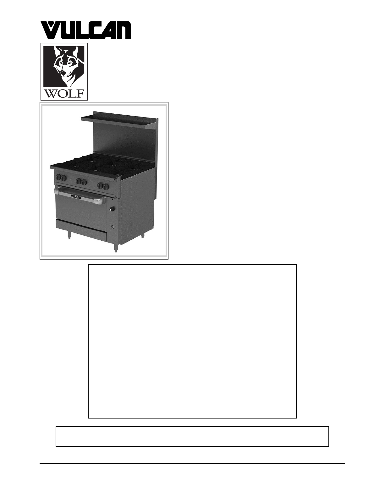
ENDURANCE / CHALLENGER
MODULAR SERIES GAS
RANGES
VULCAN
WOLF
This Manual is prepared for the use of trained Vulcan Service
Technicians and should not be used by those not properly
qualified.
12
24S
36S, 36C
48C, 48S, 48SS
60SS, 60SC, 60CS
72SS, 72SC, 72CC, 72CS
C12,
C24S
C36S, C36C
C48S, C48SS, C48C
C60SS, C60SC, C60CS
C72SS, C72SC, C72CC, C72CS
This manual is not intended to be all encompassing. If you have
not attended a Vulcan Service School for this product, you should
read, in its entirety, the repair procedure you wish to perform to
determine if you have the necessary tools, instruments and skills
required to perform the procedure. Procedures for which you
do not have the necessary tools, instruments and skills should
be performed by a trained Vulcan Service Technician.
The reproduction, transfer, sale or other use of this Manual,
without the express written consent of Vulcan, is prohibited.
This manual has been provided to you by ITW Food Equipment
Group LLC (“ITW FEG”) without charge and remains the property
of ITW FEG, and by accepting this manual you agree that you will
return it to ITW FEG promptly upon its request for such return
at any time in the future.
For additional information on Vulcan-Hart Company or to locate an authorized
parts and service provider in your area, visit our website at www.vulcanequipment.com
VULCAN-HART
DIVISION OF ITW FOOD EQUIPMENT GROUP, LLC
www.vulcanequipment.com
BALTIMORE, MD 21222
F454A (0615)
Page 2

ENDURANCE / CHALLENGER MODULAR SERIES GAS RANGES
TABLE OF CONTENTS
SERVICE UPDATES ....................................................................................... 4
SERVICE UPDATES ................................................................................... 4
GENERAL .................................................................................................. 5
INTRODUCTION ....................................................................................... 5
INSTALLATION, OPERATION AND CLEANING ......................................................... 5
LUBRICATION ......................................................................................... 5
TOOLS ................................................................................................. 5
SPECIFICATIONS ...................................................................................... 5
REMOVAL AND REPLACEMENT OF PARTS ............................................................... 6
MANIFOLD COVER .................................................................................... 6
CONTROL BRACKET COVER .......................................................................... 6
CONTROL PANEL (30" OVENS) ........................................................................ 6
KICK PANEL (24" & 30" OVENS) ....................................................................... 6
BULL NOSE ............................................................................................ 7
CONTROL BRACKET .................................................................................. 7
STANDARD OVEN PILOT ASSEMBLY AND THERMOCOUPLE ......................................... 8
STANDARD OVEN BURNER ........................................................................... 8
STANDARD OVEN THERMOSTAT (24" OVEN) ......................................................... 9
STANDARD OVEN THERMOSTAT (30" OVEN) ........................................................ 10
CONVECTION OVEN PILOT ASSEMBLY AND THERMOCOUPLE ..................................... 11
CONVECTION OVEN BURNER ....................................................................... 12
CONVECTION OVEN THERMOSTAT-COMBO VALVE ................................................ 12
CONVECTION OVEN BLOWER AND MOTOR ......................................................... 13
BURNER ORIFICE HOOD (STANDARD AND CONVECTION OVENS) ................................. 14
GAS SAFETY VALVE (STANDARD AND CONVECTION OVENS) ...................................... 14
TOP BURNER PILOT VALVE .......................................................................... 15
TOP BURNER ASSEMBLY ............................................................................ 16
TOP BURNER CONTROL VALVE ..................................................................... 16
TOP BURNER ORIFICE HOOD ....................................................................... 17
OVEN DOOR ......................................................................................... 17
GAS PRESSURE REGULATOR ....................................................................... 18
CONVECTION OVEN DOOR SWITCH ................................................................. 19
CONVECTION OVEN SOLENOID ..................................................................... 19
GRIDDLE THERMOSTAT-COMBO VALVE ............................................................ 20
GRIDDLE GAS SAFETY VALVE ....................................................................... 22
GRIDDLE PILOT ASSEMBLY AND THERMOCOUPLE ................................................. 22
GRIDDLE BURNER ORIFICE HOOD .................................................................. 23
CHARBROILER BURNER ............................................................................. 23
CHARBROILER PILOT ................................................................................ 25
SERVICE PROCEDURES AND ADJUSTMENTS ........................................................... 27
OVEN PILOT FLAME HEIGHT ......................................................................... 27
OVEN PILOT ADJUSTMENT ...................................................................... 27
OPEN TOP PILOT ADJUSTMENT ................................................................. 27
BURNER AIR SHUTTER ADJUSTMENT ............................................................... 27
REGULATOR ADJUSTMENT .......................................................................... 28
BURNER NOZZLE CHECK ............................................................................ 29
STANDARD OVEN THERMOSTAT BY-PASS FLAME ADJUSTMENT .................................. 29
STANDARD OVEN THERMOSTAT TEMPERATURE ADJUSTMENT ................................... 30
CONVECTION OVEN THERMOSTAT-COMBO VALVE ADJUSTMENT ................................. 30
OPERATION ...................................................................................... 30
ADJUSTMENT .................................................................................... 30
GRIDDLE THERMOSTAT-COMBO VALVE ADJUSTMENT ............................................. 31
OPERATION ...................................................................................... 31
ADJUSTMENT .................................................................................... 31
F45471 Rev. A (0615) Page 2 of 38
Page 3

ENDURANCE / CHALLENGER MODULAR SERIES GAS RANGES
THERMOCOUPLE TEST .............................................................................. 32
OPERATION ...................................................................................... 32
PILOT CHECKS ................................................................................... 32
THERMOCOUPLE CHECKS ...................................................................... 32
CHARBROILER PILOT ADJUSTMENT ................................................................ 33
ELECTRICAL OPERATION ................................................................................ 34
COMPONENT FUNCTION ............................................................................ 34
SEQUENCE OF OPERATION - CONVECTION OVEN ................................................. 34
SCHEMATIC DIAGRAM - CONVECTION OVENS ...................................................... 35
WIRING DIAGRAM - CONVECTION OVENS .......................................................... 36
TROUBLESHOOTING ..................................................................................... 37
TROUBLESHOOTING ................................................................................. 37
© HOBART SERVICE 2015
Page 3 of 38 F45471 Rev. A (0615)
Page 4
ENDURANCE / CHALLENGER MODULAR SERIES GAS RANGES - SERVICE UPDATES
SERVICE UPDATES
SERVICE UPDATES
This section lists the service updates to the
information in the manual.
June 2015
Added
• CHARBROILER BURNER removal.
• CHARBROILER PILOT removal.
• CHARBROILER PILOT ADJUSTMENT .
• CHARBROILER BURNER AIR SHUTTER
picture under BURNER AIR SHUTTER
ADJUSTMENT.
F45471 Rev. A (0615) Page 4 of 38
Page 5
ENDURANCE / CHALLENGER MODULAR SERIES GAS RANGES - GENERAL
GENERAL
INTRODUCTION
This manual is for the Endurance / Challenger
XL™ Modular Series Gas Ranges. Procedures in this
manual will apply to all models unless specified.
Pictures and illustrations will be of model 60SC unless
otherwise noted.
All of the information, illustrations and specifications
contained in this manual are based on the latest
product information available at the time of printing.
INSTALLATION, OPERATION AND
CLEANING
Refer to F38201 VULCAN ENDURANCE / WOLF
CHALLENGER Modular Series Gas Restaurant
Ranges I/O Manual for detailed installation, operation
and cleaning instructions.
LUBRICATION
Anderson and Forrester (or comparable) valve grease
for top burner gas valves, top burner pilot valves, and
pressure tap plugs. Apply light coat to valve/plug
threads. Valve grease must be insoluble in propane
and natural gas.
• A non perminate type sealer (preferably fast
drying) such as nail polish or equivelant for
sealing thermostat adjustment screw. If using
Loctite 242, it begins to set in approximately 10
minutes and fully cures in 24 hours according to
manufacturer.
• 3/4" pipe tee and hose barb assembly for
temporarily checking manifold pressure when a
pressure tap is not available in the gas manifold
on some models.
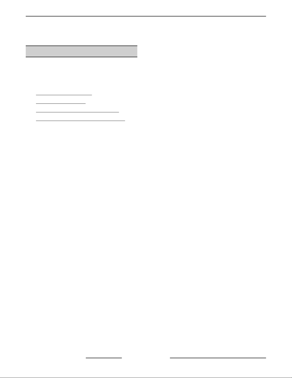
• Adaptor to test thermocouple closed circuit DC
voltages (purchase locally). Adaptors vary
between manufacturers. An example of one
adaptor type is pictured below.
Fig. 1
SPECIFICATIONS
TOOLS
Standard
• Standard set of hand tools.
• VOM with A.C. current tester (Any quality VOM
with a sensitivity of at least 20,000 ohms per volt
can be used).
Special
• Temperature tester (K type thermocouple
preferred).
• Manometer.
• Long reach phillips screwdriver #2 for installing
or removing motor assembly through the
convection oven cavity.
• Two standard 1/4"- 20 x 1" bolts (allen head
recommended). The bolts are used to relieve
spring tension on the door hinge during door
removal and installation.
• Loctite® 246™ for use on the door handle
mounting screws.
Gas Pressures
• Manifold/Operating Pressure
Natural: 5 in. W.C.
Propane: 10 in. W.C.
• Inlet Supply Pressure
Natural - Recomended 7 in. W.C. ; Minimum
5 in. W.C.
Propane - Recomended 11 in. W.C. ;
Minimum 11 in. W.C.
Maximum 14 in. W.C. (0.5 PSI) (Natural or
Propane)
Orifice Size Requirements
• See Orifice Chart in Parts Catalog F43260
ENDURANCE/CHALLENGER MODULAR
SERIES GAS RANGES.
Page 5 of 38 F45471 Rev. A (0615)
Page 6
ENDURANCE / CHALLENGER MODULAR SERIES GAS RANGES - REMOVAL AND REPLACEMENT OF PARTS
REMOVAL AND REPLACEMENT OF PARTS
MANIFOLD COVER
Shut off the gas before servicing the
unit.
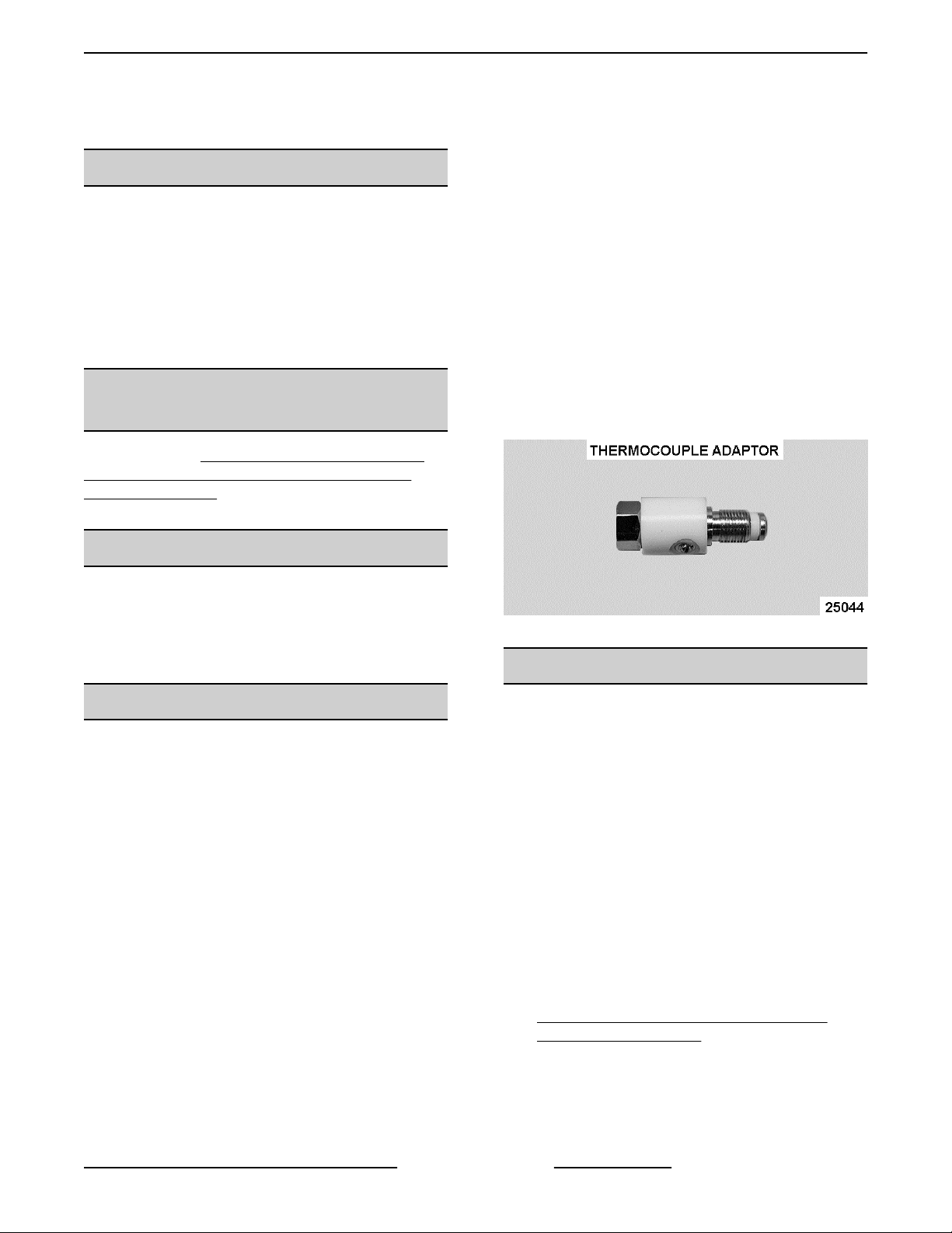
1. Pull crumb tray out.
2. Loosen set screw in the open top burner control
knobs and remove knobs.
3. Remove screws that secure manifold cover and
remove cover.
4. Reverse procedure to install.
Fig. 2
CONTROL PANEL (30" OVENS)
Disconnect the
electrical power to the machine and
follow lockout / tagout procedures.
Shut off the gas before servicing the
unit.
NOTE: Electrical power disconnect warning applies
to convection ovens.
NOTE: Removal procedure applies to standard and
convection 30" ovens.
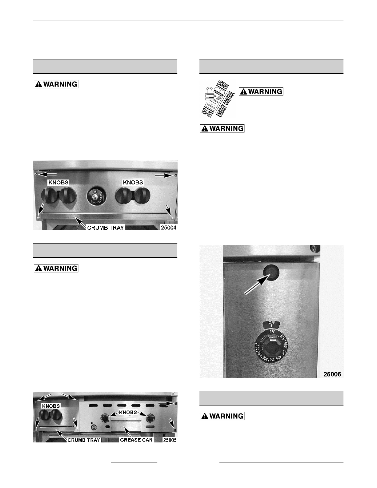
1. Pull knob from thermostat.
2. Remove hole plug at top of control panel.
3. Remove screw and lift off control panel.
4. On convection ovens only, note lead wire
locations and disconnect from power switch.
5. Reverse procedure to install.
CONTROL BRACKET COVER
Shut off the gas before servicing the
unit.
1. Pull grease can out.
2. Pull knobs from thermostats.
3. If removing control bracket cover from oven with
a 12" open top burner module and 24" griddle top
module:
A. Pull crumb tray out of 12" section if installed.
B. Loosen set screw in the open top burner
control knobs and remove knobs.
4. Remove screws that secure control bracket
cover and remove the bracket.
5. Reverse procedure to install.
Convection Oven Panel Shown
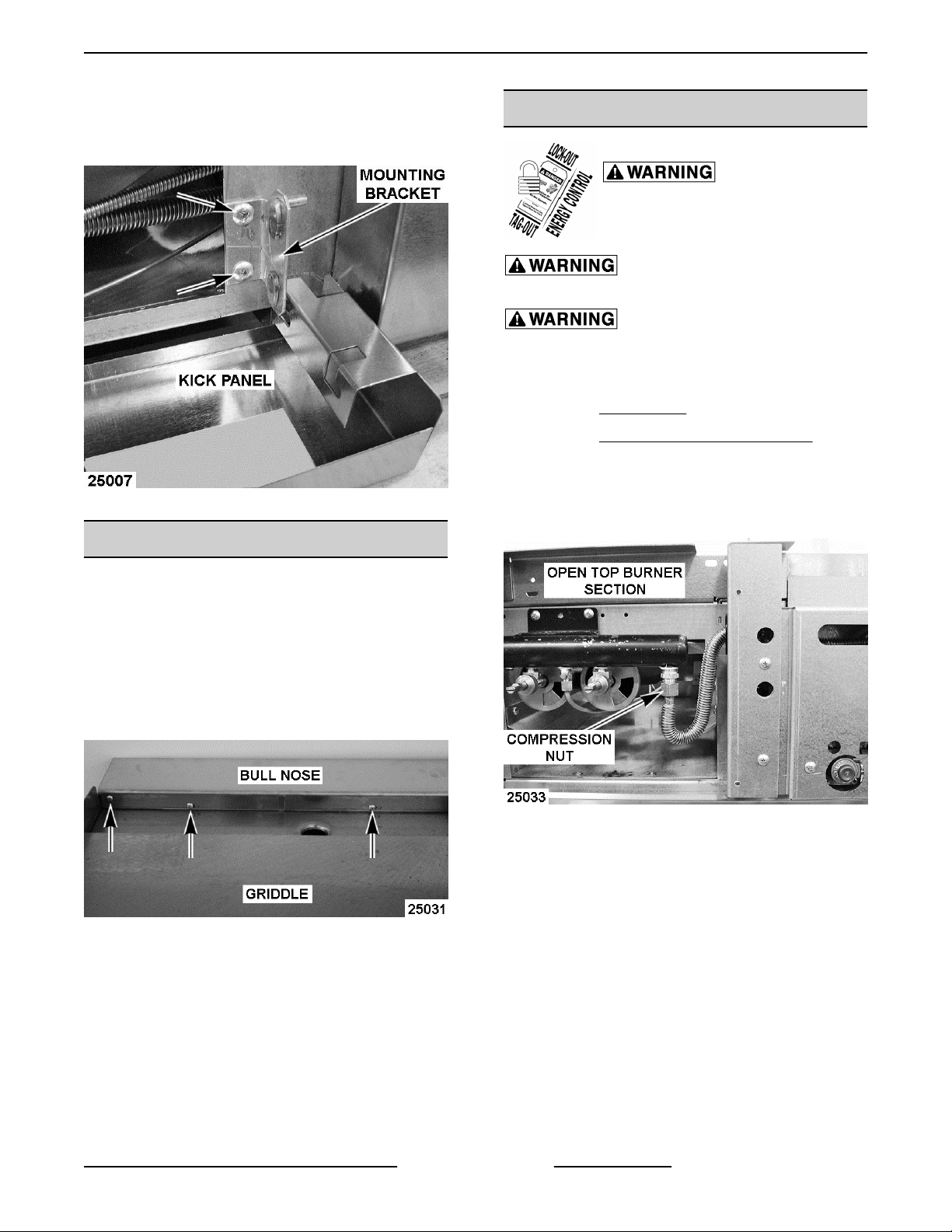
KICK PANEL (24" & 30" OVENS)
Shut off the gas before servicing the
unit.
1. Lift up on kick panel and rotate down 90°.
Fig. 3
F45471 Rev. A (0615) Page 6 of 38
Page 7
ENDURANCE / CHALLENGER MODULAR SERIES GAS RANGES - REMOVAL AND REPLACEMENT OF PARTS
2. Remove screws securing kick panel mounting
brackets (2) to the oven and remove kick panel.
3. Reverse procedure to install.
Fig. 5
BULL NOSE
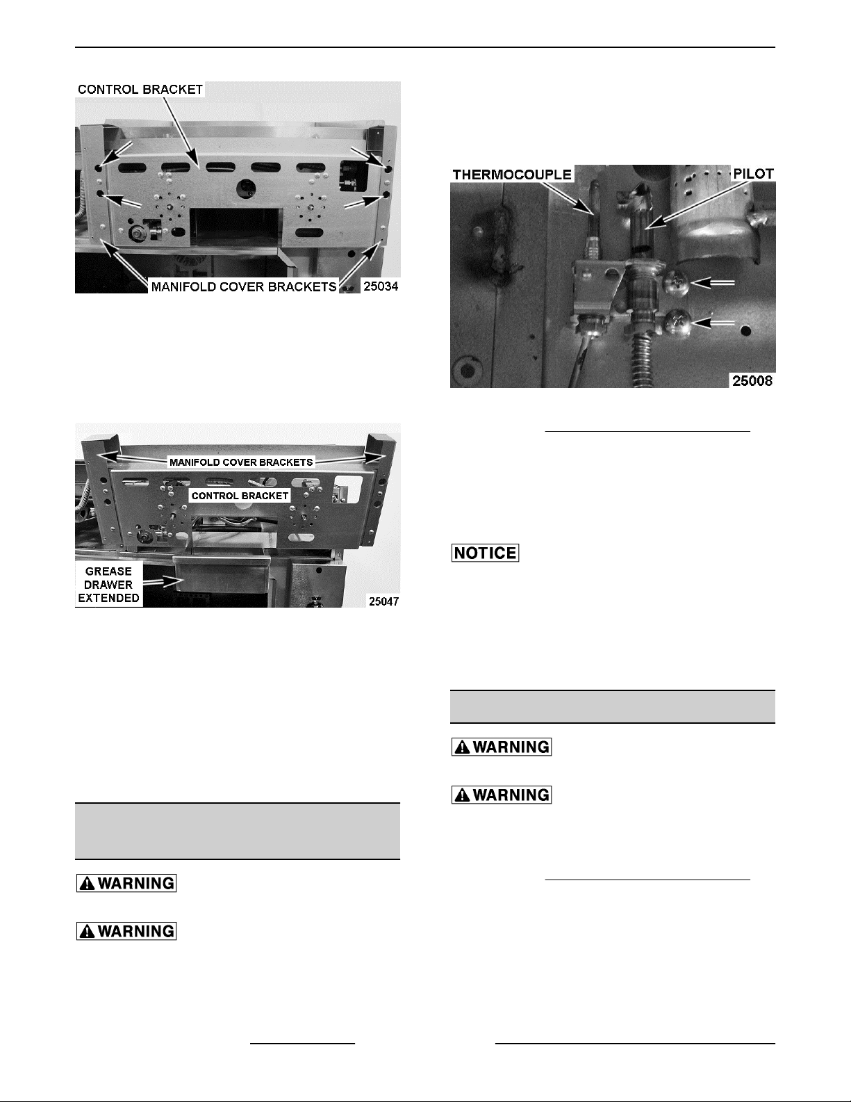
CONTROL BRACKET
Disconnect the
electrical power to the machine and
follow lockout / tagout procedures.
Shut off the gas before servicing the
unit.
All gas joints disturbed during
servicing must be checked for leaks. Check with a
soap and water solution (bubbles). Do not use an open
flame.
1. Remove BULL NOSE.
2. Remove CONTROL BRACKET COVER.
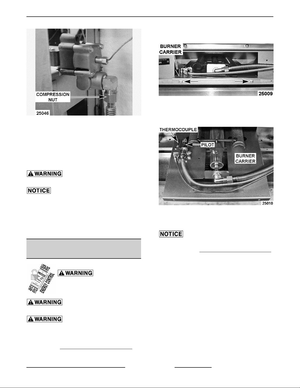
3. If installed, remove compression nut on the
flexible tubing gas line that supplies gas to the
manifold on the adjacent open top burner
section.
1. Turn top burners and griddle off.
2. Remove front row of top burner grates on ranges
with open top burners.
3. Remove all screws securing bull nose to range.
The total number of screws depend on the width
of the range.
4. Lift bull nose off range.
Fig. 6
5. Reverse procedure to install.
Fig. 7
4. Loosen the recessed screws (4) through the
access holes on the two manifold cover brackets
(L & R) that secure the control bracket to the
oven. The bracket mounting holes are keyed for
removal of the control bracket.
Page 7 of 38 F45471 Rev. A (0615)
Page 8
ENDURANCE / CHALLENGER MODULAR SERIES GAS RANGES - REMOVAL AND REPLACEMENT OF PARTS
2. Remove cavity bottom by lifting up and sliding
out.
3. Remove screws securing oven pilot assembly to
burner carrier.
Fig. 8
5. Lift the control bracket up and tilt forward to
remove bracket from mounting screws.
6. Partially install the grease drawer leaving enough
of the drawer extended to support the control
bracket while servicing.
4. Lower the KICK PANEL (24" & 30" OVENS).
Fig. 10
Fig. 9
7. Griddle controls are now accessible for removal.
A. If replacing control bracket, remove screws
securing griddle controls to bracket.
B. Remove manifold cover brackets (L & R)
from each end of the control bracket as
necessary (2 screws for each bracket).
8. Reverse procedure to install and check for proper
operation.
STANDARD OVEN PILOT
ASSEMBLY AND THERMOCOUPLE
5. Pull oven pilot assembly out through opening in
lower oven frame.
6. If replacing thermocouple only, remove
thermocouple from oven pilot assembly and gas
safety valve. Continue to last step.
When installing, do not bend and kink the
capillary tube or damage to the component may occur.
7. If replacing oven pilot assembly, remove pilot
tubing and thermocouple from oven pilot
assembly.
8. Reverse procedure to install and check for proper
operation.
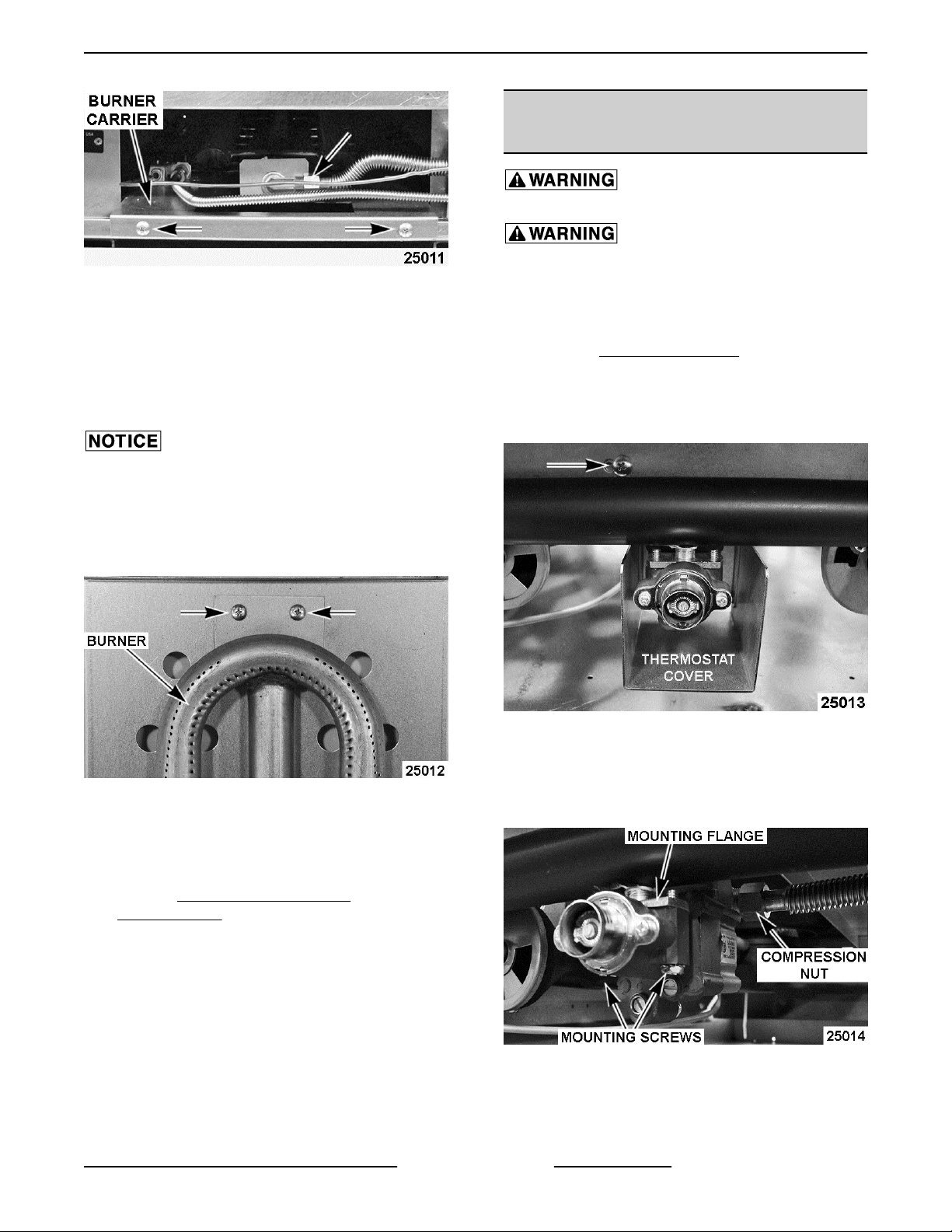
STANDARD OVEN BURNER
Shut off the gas before servicing the
unit.
All gas joints disturbed during
servicing must be checked for leaks. Check with a
soap and water solution (bubbles). Do not use an open
flame.
Shut off the gas before servicing the
unit.
All gas joints disturbed during
servicing must be checked for leaks. Check with a
soap and water solution (bubbles). Do not use an open
flame.
1. Remove bottom oven rack(s) and rack guides.
F45471 Rev. A (0615) Page 8 of 38
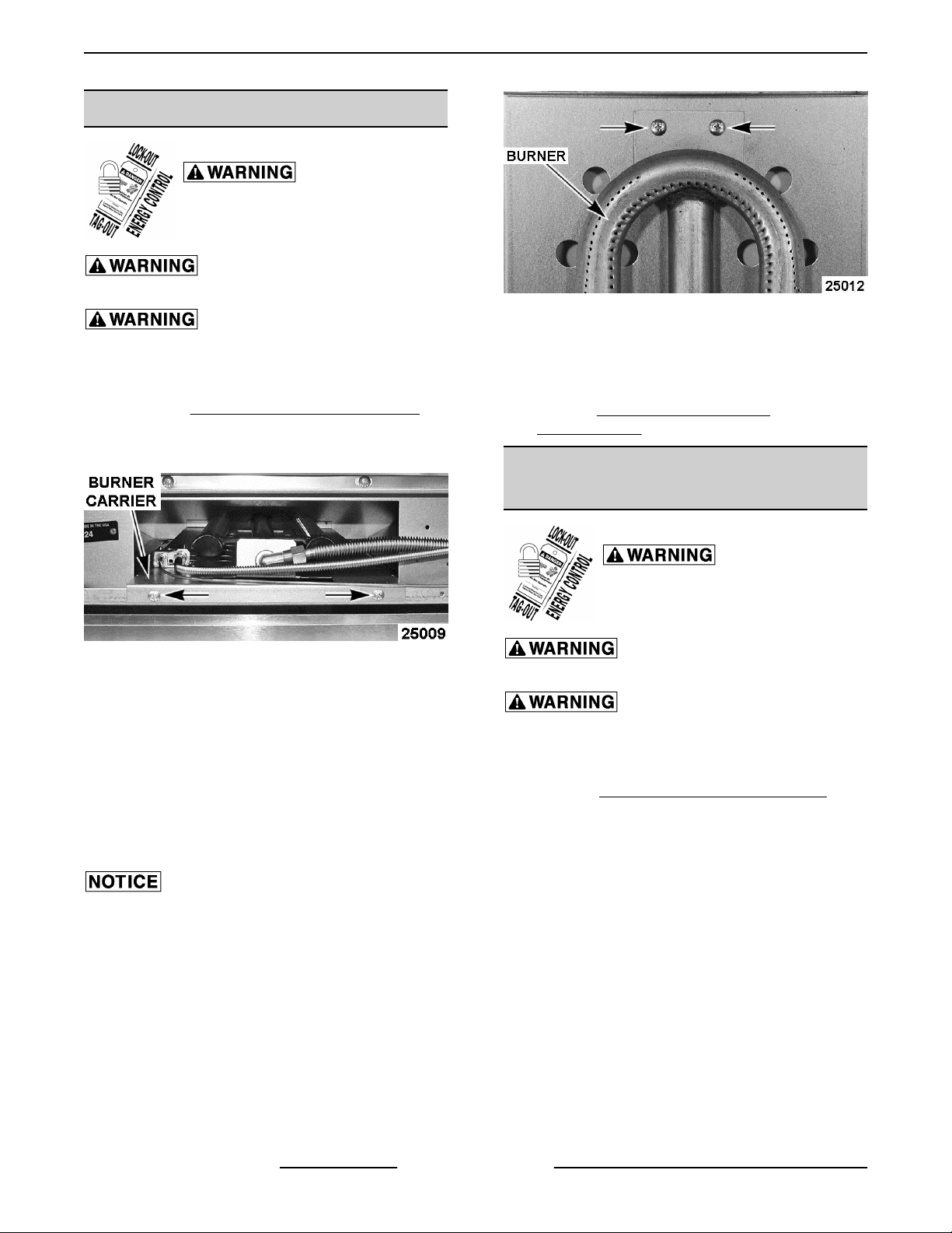
1. Lower the KICK PANEL (24" & 30" OVENS).
2. Hold the tab on burner carrier with plyers to
3. Remove screws securing burner carrier to oven
support it then remove compression nut from
burner elbow fitting to disconnect gas supply
tubing.
frame.
Page 9
ENDURANCE / CHALLENGER MODULAR SERIES GAS RANGES - REMOVAL AND REPLACEMENT OF PARTS
STANDARD OVEN THERMOSTAT
(24" OVEN)
Shut off the gas before servicing the
unit.
All gas joints disturbed during
servicing must be checked for leaks. Check with a
Fig. 11
4. Pull burner carrier out through opening in lower
oven frame enough to access the oven pilot
assembly.
5. Remove screws securring oven pilot assembly to
burner carrier. Move oven pilot assembly away
from burner.
Do not bend and kink the capillary tube or
damage to the control may occur.
6. Pull burner carrier with burner attached out from
oven.
soap and water solution (bubbles). Do not use an open
flame.
1. Pull out crumb tray.
2. Remove MANIFOLD COVER.
3. Remove oven thermostat knob.
4. Remove screw securing thermostat cover to
oven frame.
7. Remove screws securring burner to the burner
carrier.
Fig. 12
8. Slide oven burner off the burner nozzle to
remove.
9. Reverse procedure to install.
10. Perform BURNER AIR SHUTTER
ADJUSTMENT.
Fig. 13
5. Remove compression nut from elbow fitting at
the rear of thermostat.
6. Remove screws securing thermostat to mounting
flange.
Fig. 14
A. Inspect mounting flange and gasket. If okay,
they may be used during installation. If not
okay, remove and install replacement
flange.
Page 9 of 38 F45471 Rev. A (0615)
Page 10
ENDURANCE / CHALLENGER MODULAR SERIES GAS RANGES - REMOVAL AND REPLACEMENT OF PARTS
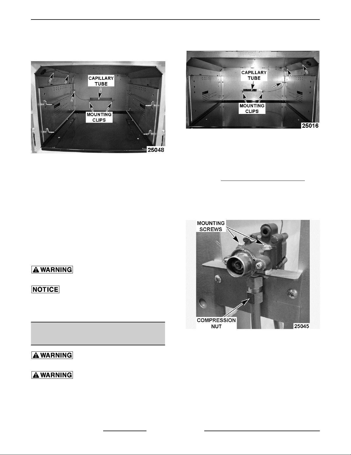
7. Open oven door and remove oven racks.
8. Remove screws securing capillary tube mounting
clips (5) inside the oven cavity.
Fig. 15
NOTE: Capillary tube is permanently attached to
thermostat-combo valve.
9. Remove all mounting clips from capillary tube
and retain for reuse.
10. Pull capillary tube through the hole in oven
sidewall and remove thermostat from oven.
A. Remove insulation sleeve from capillary
tube for installation on replacement
thermostat capillary tube.
2. Remove screws securing capillary tube mounting
clips (5) inside the oven cavity.
Standard 30" oven
NOTE: Capillary tube is permanently attached to
thermostat.
3. Remove all mounting clips from capillary tube
and retain for reuse.
4. Remove CONTROL PANEL (30" OVENS).
5. Remove compression nuts from thermostat
fittings (front & rear).
6. Remove screws securing thermostat to mounting
bracket.
B. Note orientation of compression fitting
elbow on valve body and remove for
installation on replacement valve body.
Clean pipe threads and apply thread
sealant that is suitable for use with propane gases.
When installing, do not bend and kink the
capillary tube or damage to the control may occur.
11. Reverse procedure to install and check for proper
operation.
STANDARD OVEN THERMOSTAT
(30" OVEN)
Shut off the gas before servicing the
unit.
All gas joints disturbed during
servicing must be checked for leaks. Check with a
soap and water solution (bubbles). Do not use an open
flame.
1. Open oven door and remove oven racks.
Fig. 17
F45471 Rev. A (0615) Page 10 of 38
Page 11
ENDURANCE / CHALLENGER MODULAR SERIES GAS RANGES - REMOVAL AND REPLACEMENT OF PARTS
2. Remove screws securing burner carrier to oven
frame.
Fig. 19
3. Pull burner carrier out through opening in lower
Fig. 18
7. Remove gas line tubing from thermostat.
8. Pull capillary tube through the hole in oven
sidewall and remove thermostat from oven.
A. Note orientation of compression fittings on
thermostat body and remove for installation
on replacement valve body.
oven frame enough to access the oven pilot
assembly.
Clean pipe threads and apply thread
sealant that is suitable for use with propane gases.
When installing, do not bend and kink the
capillary tube or damage to the control may occur.
NOTE: When installing thermostat capillary tube,
push any insulation back through grommet and
remove loose insulation from oven cavity.
9. Reverse procedure to install and check for proper
operation.
CONVECTION OVEN PILOT
ASSEMBLY AND THERMOCOUPLE
Disconnect the
electrical power to the machine and
follow lockout / tagout procedures.
Shut off the gas before servicing the
unit.
All gas joints disturbed during
servicing must be checked for leaks. Check with a
soap and water solution (bubbles). Do not use an open
flame.
Fig. 20
4. If replacing thermocouple only, remove
thermocouple from oven pilot assembly.
When installing, do not bend and kink the
capillary tube or damage to the component may occur.
A. Remove CONTROL PANEL (30" OVENS).
B. Remove thermocouple from gas safety
valve and remove thermocouple from oven.
Continue to last step.
5. If replacing oven pilot assembly, remove pilot
tubing and thermocouple from oven pilot
assembly.
6. Remove screws securing oven pilot assembly to
burner carrier.
7. Reverse procedure to install and check for proper
operation.
1. Lower the KICK PANEL (24" & 30" OVENS).
Page 11 of 38 F45471 Rev. A (0615)
Page 12
ENDURANCE / CHALLENGER MODULAR SERIES GAS RANGES - REMOVAL AND REPLACEMENT OF PARTS
CONVECTION OVEN BURNER
Disconnect the
electrical power to the machine and
follow lockout / tagout procedures.
Shut off the gas before servicing the
unit.
All gas joints disturbed during
servicing must be checked for leaks. Check with a
soap and water solution (bubbles). Do not use an open
flame.
1. Lower the KICK PANEL (24" & 30" OVENS).
2. Remove screws securing burner carrier to oven
frame.
8. Slide oven burner off the burner nozzle to
remove.
9. Reverse procedure to install.
10. Perform
ADJUSTMENT.
BURNER AIR SHUTTER
Fig. 22
CONVECTION OVEN
THERMOSTAT-COMBO VALVE
Fig. 21
3. Pull burner carrier out through opening in lower
oven frame enough to access the oven pilot
assembly and burner elbow fitting.
4. Hold the tab on burner carrier with plyers to
support then remove compression nut from
burner elbow fitting.
5. Remove screws securing oven pilot assembly to
burner carrier. Move pilot assembly away from
burner.
Do not bend and kink the capillary tube or
damage to the control may occur.
6. Pull burner carrier with burner attached out from
oven.
7. Remove screws securing burner to the burner
carrier.
Disconnect the
electrical power to the machine and
follow lockout / tagout procedures.
Shut off the gas before servicing the
unit.
All gas joints disturbed during
servicing must be checked for leaks. Check with a
soap and water solution (bubbles). Do not use an open
flame.
1. Remove CONTROL PANEL (30" OVENS).
2. Remove compression nuts from thermostatcombo valve fittings.
3. Remove screws securing thermostat-combo
valve to mounting bracket.
F45471 Rev. A (0615) Page 12 of 38
Page 13

ENDURANCE / CHALLENGER MODULAR SERIES GAS RANGES - REMOVAL AND REPLACEMENT OF PARTS
Clean pipe threads and apply thread
sealant that is suitable for use with propane gases.
When installing, do not bend and kink the
capillary tube or damage to the control may occur.
NOTE: When installing thermostat capillary tube,
push any insulation back through grommet and
remove loose insulation from oven cavity.
9. Reverse procedure to install and check for proper
operation.
CONVECTION OVEN BLOWER AND
MOTOR
Fig. 23
4. Remove thermostat-combo valve from gas line
tubing.
5. Remove oven racks.
6. Open oven door and remove screws securing
capillary tube mounting clips (4) at the top of oven
cavity.
Fig. 24
NOTE: Capillary tube is permanently attached to
thermostat-combo valve.
7. Remove all mounting clips from capillary tube
and retain for reuse.
Disconnect the
electrical power to the machine and
follow lockout / tagout procedures.
1. Remove cover from electrical junction box at the
rear of range.
2. Disconnect motor wiring at junction box.
3. Loosen screw securing armored cable to junction
box.
4. Remove oven racks and rack guides from oven.
5. Place cardboard over the oven cavity bottom to
protect it during motor removal.
6. Remove screws securing motor mount panel to
the oven. Pull the assembly out from the oven.
8. Pull capillary tube through the hole in oven
sidewall and remove thermostat-combo valve
from oven.
A. Remove insulation sleeve from capillary
tube for installation on replacement
thermostat capillary tube.
B. Note orientation of compression fittings on
valve body and remove for installation on
replacement valve body.
Fig. 25
7. Remove screws (4) securing blower cover to
motor mount panel.
Page 13 of 38 F45471 Rev. A (0615)
Page 14

ENDURANCE / CHALLENGER MODULAR SERIES GAS RANGES - REMOVAL AND REPLACEMENT OF PARTS
BURNER ORIFICE HOOD
(STANDARD AND CONVECTION
OVENS)
1. Access burner for the type of oven being serviced
as outlined under STANDARD OVEN BURNER
or CONVECTION OVEN BURNER.
2. Remove the orifice hood from fitting.
3. Perform BURNER NOZZLE CHECK.
Fig. 26
8. Loosen bolts (2) securing blower to motor shaft
then remove blower.
9. If replacing blower only, proceed to last step. If
replacing motor, continue with procedure.
10. Remove mounting nuts and spacers securing
motor mounting brackets (2) to motor mount
panel.
Fig. 27
A. Remove motor mounting brackets from
motor for reuse.
B. Remove cover from motor junction box,
disconnect wires and remove armored
cable from motor junction box.
4. Reverse procedure to install.
5. Check for proper operation.
GAS SAFETY VALVE (STANDARD
AND CONVECTION OVENS)
Disconnect the
electrical power to the machine and
follow lockout / tagout procedures.
Shut off the gas before servicing the
unit.
All gas joints disturbed during
servicing must be checked for leaks. Check with a
soap and water solution (bubbles). Do not use an open
flame.
1. Remove CONTROL PANEL (30" OVENS) on
standard and convection ovens or lower the
KICK PANEL (24" & 30" OVENS) on standard
24" ovens.
2. Remove pilot tubing and thermocouple from gas
safety valve.
3. Remove inlet and outlet gas lines from gas safety
valve.
C. Inspect the motor insulation located
between the motor mounting brackets and
the motor mount panel. Replace if
damaged.
11. Install motor mounting brackets and armored
cable onto replacement motor.
12. Reverse procedure to install and check for proper
operation.
F45471 Rev. A (0615) Page 14 of 38
Page 15

ENDURANCE / CHALLENGER MODULAR SERIES GAS RANGES - REMOVAL AND REPLACEMENT OF PARTS
TOP BURNER PILOT VALVE
Disconnect the
electrical power to the machine and
follow lockout / tagout procedures.
Shut off the gas before servicing the
unit.
All gas joints disturbed during
servicing must be checked for leaks. Check with a
Gas Safety Valve on Standard 24" Oven
soap and water solution (bubbles). Do not use an open
flame.
1. On the module section being serviced, loosen set
screw on top burner knobs and remove knobs
from manual valve.
2. Remove MANIFOLD COVER.
Gas Safety Valve on 30" Convection Oven
NOTE: Safety valve replacement is identical on 30
inch wide standard ovens.
4. Remove screws securing gas safety valve to
mounting bracket and remove the valve. On 24"
standard ovens, spacers are installed between
the valve and mounting bracket. Retain spacers
for reuse. Spacer locations shown in picture
25022 "Gas Safety Valve on Standard 24"
Oven".
5. Remove compression fittings and tubing from
gas safety valve for installation on replacement
valve.
Clean pipe threads and apply thread
sealant that is suitable for use with propane gases.
3. Remove compression nut securing pilot tube to
pilot valve.
4. Remove pilot valve from the manifold.
Fig. 30
5. Reverse procedure to install.
Clean pipe threads and apply thread
sealant that is suitable for use with propane gases.
Do not over tighten pilot valve or damage
to the threads may ocurr.
6. Check OVEN PILOT FLAME HEIGHT under
Open Top Burner Adjustment.
6. Reverse procedure to install and check for proper
operation.
Page 15 of 38 F45471 Rev. A (0615)
Page 16

ENDURANCE / CHALLENGER MODULAR SERIES GAS RANGES - REMOVAL AND REPLACEMENT OF PARTS
TOP BURNER ASSEMBLY
Disconnect the
electrical power to the machine and
follow lockout / tagout procedures.
Shut off the gas before servicing the
unit.
All gas joints disturbed during
servicing must be checked for leaks. Check with a
soap and water solution (bubbles). Do not use an open
flame.
1. Remove top burner grates (front and rear) from
the module section being serviced.
6. Check for proper operation.
7. Verify BURNER AIR SHUTTER ADJUSTMENT.
Fig. 32
2. Remove pilot from mounting clip on the top
burner assembly. Move pilot away from burner
assembly.
Fig. 31
3. Lift burner heads off the top burner assembly.
4. Lift the top burner assembly at the rear and pull
away from manual valves.
TOP BURNER CONTROL VALVE
Disconnect the
electrical power to the machine and
follow lockout / tagout procedures.
Shut off the gas before servicing the
unit.
All gas joints disturbed during
servicing must be checked for leaks. Check with a
soap and water solution (bubbles). Do not use an open
flame.
A. Remove pilot mounting clip and flash tube
from the top burner assembly for resuse on
replacement burner assembly.
5. Reverse procedure to install.
NOTE: When installing, ensure that each end of the
flash tube is aligned with the ignition ports on the
burner “venturi” casting for proper burner ignition.
F45471 Rev. A (0615) Page 16 of 38
1. Remove MANIFOLD COVER.
2. Remove TOP BURNER ASSEMBLY.
3. Remove TOP BURNER PILOT VALVE.
4. Remove top burner control valve from the
Fig. 33
manifold.
Page 17

ENDURANCE / CHALLENGER MODULAR SERIES GAS RANGES - REMOVAL AND REPLACEMENT OF PARTS
5. Inspect the top control valve for wear and
damage, replace as necessary.
6. Reverse procedure to install.
Clean pipe threads and apply thread
sealant that is suitable for use with propane gases.
NOTE: When installing, ensure top burner control
valve is aligned and centered in the burner assembly
opening. The valve must be perpendicular to the
manifold.
7. Check for proper operation.
TOP BURNER ORIFICE HOOD
1. Access top burner orifice hood as outlined under
TOP BURNER ASSEMBLY.
2. Remove the orifice hood from top burner control
valve.
3. Reverse procedure to install.
4. Check for proper operation.
OVEN DOOR
5. Close door leaving enough space to clear the
oven gas manifold cover during removal. As the
door approaches this position, you should notice
a decrease in the spring tension on the door.
6. Remove door as follows:
A. Hold door at bottom corners then lift the door
up and out to disengage the hinges.
B. The notch on swivel hinge must release
from bottom edge of the door hinge stop to
remove door. As needed, lift up on the
swivel hinges using forefinger to aid in
releasing.
C. The spring-loaded hinge must release from
the roller inside the slot on door hinge stop
to remove door.
7. If replacing door or door spring hinge, position the
door face down. Press down on hinge enough to
relieve spring force then remove bolt from door
hinge slot.
Installation
1. Compress each spring-loaded hinge enough to
insert the bolt into the slot at top of hinge.
Removal
1. Remove CONTROL PANEL (30" OVENS).
NOTE: Removal of control panel is to provide
additional space on the right side of door to ease door
removal and installation.
2. Lower KICK PANEL (24" & 30" OVENS).
3. Fully open the oven door.
4. Insert a 1/4"-20 x 1" bolt (see TOOLS) into each
door hinge slot at the top of the spring loaded
hinge.
2. Hold door at bottom corners while facing the oven
cavity. Place knee on the front of door to help
balance it as necessary during installation.
A. Using index fingers, lift swivel hinges until
they touch the spring-loaded hinges and
hold in place.
B. Tilt the top of door toward the oven so that
the swivel hinge is at a slightly downward
angle to pass between the bar and bottom
edge of door hinge stop.
C. Insert hinges into the slots making sure that
the spring-loaded hinges go above the bar
to catch on the roller and the swivel hinges
go underneath the bar to catch on the
bottom edge of door hinge slot.
D. Lower the door and position it as necessary
to engage the swivel hinge slots with the
bottom edge of both door hinge slots.
Fig. 34
Page 17 of 38 F45471 Rev. A (0615)
Page 18

ENDURANCE / CHALLENGER MODULAR SERIES GAS RANGES - REMOVAL AND REPLACEMENT OF PARTS
GAS PRESSURE REGULATOR
Disconnect the
electrical power to the machine and
follow lockout / tagout procedures.
Shut off the gas before servicing the
unit.
All gas joints disturbed during
servicing must be checked for leaks. Check with a
soap and water solution (bubbles). Do not use an open
flame.
Fig. 35
3. Fully open door to check operation. If bottom
edge of door rubs the front edge of cavity bottom
then the swivel hinge is not engaged as
described.
A. To seat the swivel hinge, open door
approximately 30° and pull in the same
direction on the door handle. The hinge
should drop into place.
4. Open door and check operation. If okay, remove
bolts and close door. If not okay, remove door
and repeat installation procedure.
5. On convection ovens, verify door switch is
operating properly.
6. Reinstall oven control panel.
7. Raise kick panel.
Clean pipe threads and apply thread
sealant that is suitable for use with propane gases.
1. Thread regulator onto pipe hand tight with arrow
pointing in direction of gas flow to the range.
Fig. 36
2. Tighten regulator securely in horizontal position
with the regulator adjustment upward as
described on regulator.
NOTE: Regulator will not function properly without
adjustment screw pointing upward.
3. Connect supply gas line to gas pressure
4. Adjust regulator as outlined in REGULATOR
F45471 Rev. A (0615) Page 18 of 38
regulator inlet.
ADJUSTMENT.
Page 19

ENDURANCE / CHALLENGER MODULAR SERIES GAS RANGES - REMOVAL AND REPLACEMENT OF PARTS
CONVECTION OVEN DOOR
SWITCH
Disconnect the
electrical power to the machine and
follow lockout / tagout procedures.
NOTE: Door switch is installed on Convection Ovens
only.
1. Remove
2. Remove single mounting nut securing door
switch bracket to safety valve mounting bracket.
3. Remove screws securing door switch bracket to
oven frame and remove bracket from control
area.
CONTROL PANEL (30" OVENS).
Fig. 38
7. Reverse procedure to install and check door
switch for proper operation.
CONVECTION OVEN SOLENOID
Disconnect the
electrical power to the machine and
follow lockout / tagout procedures.
Shut off the gas before servicing the
unit.
All gas joints disturbed during
servicing must be checked for leaks. Check with a
soap and water solution (bubbles). Do not use an open
flame.
Fig. 37
4. Open door to unoperate the switch.
5. Note lead wire locations and disconnect from
door switch.
6. Remove screws and mounting nuts securing
door switch to door switch bracket.
1. Remove door switch bracket as outlined under
CONVECTION OVEN DOOR SWITCH. Allow
bracket to rest at the bottom of control area.
2. Remove screws securing the mounting bracket
that holds the safety valve, oven thermostat and
the oven solenoid to the oven frame.
Page 19 of 38 F45471 Rev. A (0615)
Page 20

ENDURANCE / CHALLENGER MODULAR SERIES GAS RANGES - REMOVAL AND REPLACEMENT OF PARTS
GRIDDLE THERMOSTAT-COMBO
VALVE
Disconnect the
electrical power to the machine and
follow lockout / tagout procedures.
Shut off the gas before servicing the
unit.
All gas joints disturbed during
servicing must be checked for leaks. Check with a
soap and water solution (bubbles). Do not use an open
flame.
1. Remove BULL NOSE.
Fig. 39
3. Remove compression nuts on the inlet and outlet
of solenoid.
4. Remove screws and mounting nuts securing
solenoid to bracket.
5. Disconnect lead wires from solenoid.
2. Raise griddle plate from the front and support
using 4x4 blocks.
3. Pull thermostat bulb out of the holder for the
thermostat-combo valve being replaced.
NOTE: Capillary tube is permanently attached to
thermostat-combo valve.
Fig. 41
4. Remove CONTROL BRACKET COVER.
5. If installed, remove compression nut on the
Fig. 40
6. Remove fittings from solenoid for reuse on
replacement valve.
Clean pipe threads and apply thread
sealant that is suitable for use with propane gases.
7. Reverse procedure to install and check for proper
operation.
F45471 Rev. A (0615) Page 20 of 38
flexible tubing gas line that supplies gas to the
manifold on the adjacent open top burner
section.
Page 21

ENDURANCE / CHALLENGER MODULAR SERIES GAS RANGES - REMOVAL AND REPLACEMENT OF PARTS
9. Remove compression nuts from thermostatcombo valve fittings for the thermostat being
replaced.
Fig. 42
6. Loosen the recessed screws (4) through the
access holes on the two manifold cover brackets
(L & R) that secure the control bracket to the
oven. The bracket mounting holes are keyed for
removal of the control bracket.
10. Remove screws (3) securing thermostat-combo
valve to the control bracket and remove the
thermostat-combo valve.
Fig. 45
Fig. 43
7. Lift up control bracket and tilt forward to access
griddle thermostat-combo valves.
8. Partially install the grease drawer leaving enough
of the drawer extended to support the control
bracket while servicing.
Fig. 44
Page 21 of 38 F45471 Rev. A (0615)
Fig. 46
A. Note orientation of compression fittings on
the thermostat-combo valve and remove for
installation on replacement valve.
B. Remove insulation sleeve from capillary
tube for installation on replacement
thermostat capillary tube.
Clean pipe threads and apply thread
sealant that is suitable for use with propane gases.
When installing, do not bend and kink the
capillary tubes or damage to the controls may occur.
Ensure capillary tubes are routed properely through
mounting slots before lowering the griddle or damage
to the controls may occur.
NOTE: When installing, ensure orifice hood is aligned
and centered in the burner assembly opening. The
griddle orifice bracket must be perpendicular to the
manifold.
Page 22

ENDURANCE / CHALLENGER MODULAR SERIES GAS RANGES - REMOVAL AND REPLACEMENT OF PARTS
11. Reverse procedure to install and check for proper
operation.
GRIDDLE GAS SAFETY VALVE
Disconnect the
electrical power to the machine and
follow lockout / tagout procedures.
Shut off the gas before servicing the
unit.
All gas joints disturbed during
servicing must be checked for leaks. Check with a
soap and water solution (bubbles). Do not use an open
flame.
1. Remove CONTROL BRACKET.
2. Remove pilot tubing and thermocouple from gas
safety valve.
3. Remove compression nuts from gas safety valve
fittings.
Fig. 47
4. Remove screws (2) securing gas safety valve to
the control bracket and remove the valve.
A. Note orientation of compression fittings on
the valve and remove for installation on
replacement valve.
Fig. 48
When installing, do not bend and kink the
capillary tube or damage to the control may occur.
Clean pipe threads and apply pipe joint
compound. Any pipe joint compound used must be
resistant to the reaction of propane gases.
NOTE: When installing, ensure orifice hood is aligned
and centered in the burner assembly opening.
5. Reverse procedure to install and check for proper
operation.
GRIDDLE PILOT ASSEMBLY AND
THERMOCOUPLE
Disconnect the
electrical power to the machine and
follow lockout / tagout procedures.
Shut off the gas before servicing the
unit.
All gas joints disturbed during
servicing must be checked for leaks. Check with a
soap and water solution (bubbles). Do not use an open
flame.
1. Remove CONTROL BRACKET.
2. Remove screws (2) securing pilot assembly
3. If replacing pilot assembly, remove pilot tubing
F45471 Rev. A (0615) Page 22 of 38
mounting bracket to griddle burner box.
A. If replacing thermocouple only, remove
thermocouple from pilot assembly and gas
safety valve. Continue to last step.
and thermocouple from pilot assembly.
Page 23

ENDURANCE / CHALLENGER MODULAR SERIES GAS RANGES - REMOVAL AND REPLACEMENT OF PARTS
NOTE: When installing, ensure orifice hood is aligned
and centered in the burner assembly opening.
CHARBROILER BURNER
Shut off the gas before servicing the
unit.
Disconnect the
electrical power to the machine and
follow lockout / tagout procedures.
Fig. 49
4. Remove screws (2) securing pilot assembly to
mounting bracket.
5. Reverse procedure to install and check for proper
operation.
When installing, do not bend and kink the
capillary tube or damage to the control may occur.
NOTE: When installing, ensure orifice hood is aligned
and centered in the burner assembly opening.
GRIDDLE BURNER ORIFICE HOOD
Shut off the gas before servicing the
unit.
All gas joints disturbed during
servicing must be checked for leaks. Check with a
soap and water solution (bubbles). Do not use an open
flame.
1. Remove CONTROL BRACKET.
2. Remove the orifice hood from fitting.
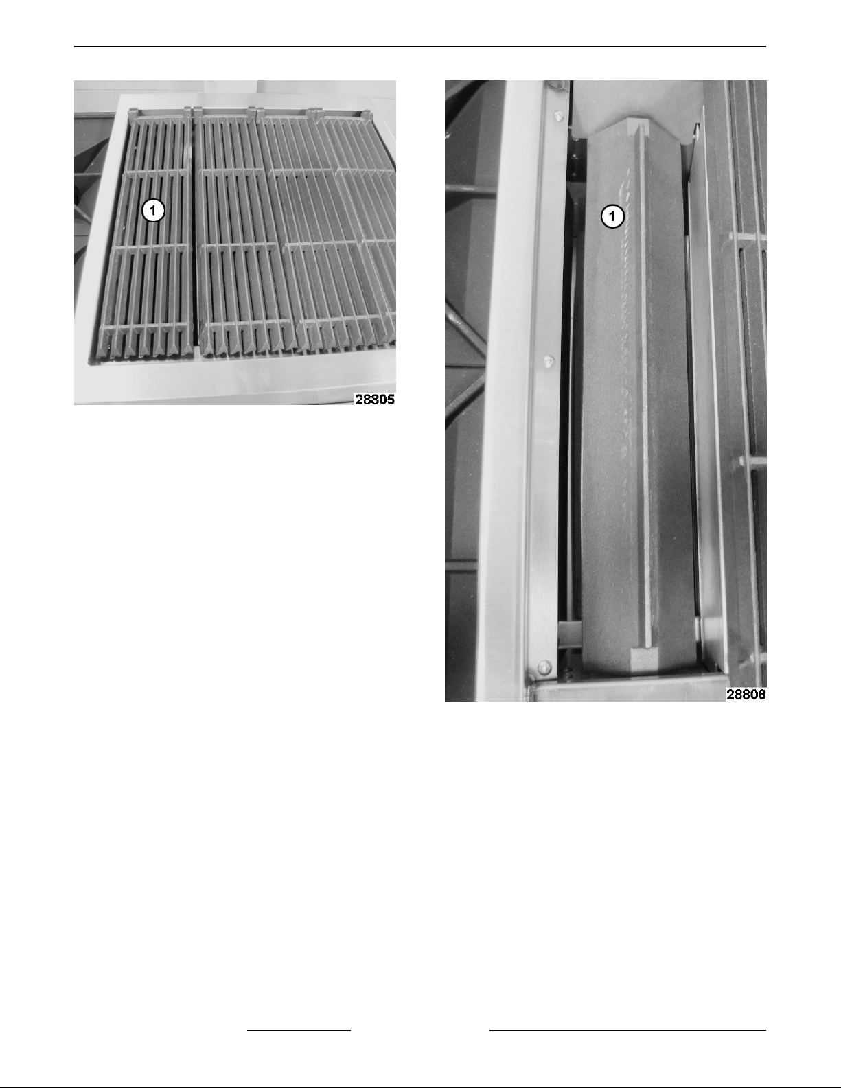
Fig. 51
Charbroiler Burner Components - Front View
• [1] Grate
• [2] Radiant
• [3] Burner
• [4] Deflector
1. Remove grate [1] from charbroiler.
Fig. 50
3. Reverse procedure to install and check for proper
operation.
Page 23 of 38 F45471 Rev. A (0615)
Page 24
ENDURANCE / CHALLENGER MODULAR SERIES GAS RANGES - REMOVAL AND REPLACEMENT OF PARTS
Fig. 52
2. Remove radiant [1] to access burner.
Fig. 53
3. Remove burner [1] and deflector [2] by lifting at
the rear of burner.
F45471 Rev. A (0615) Page 24 of 38
Page 25

ENDURANCE / CHALLENGER MODULAR SERIES GAS RANGES - REMOVAL AND REPLACEMENT OF PARTS
Fig. 55
5. To Install:
A. Install deflector onto replacement burner.
6. Verify BURNER AIR SHUTTER ADJUSTMENT.
Fig. 54
4. Remove burner rod [1] securing deflector [2] to
burner.
7. Install radiant above the burner.
8. Install grate.
9. Check for proper operation.
CHARBROILER PILOT
Shut off the gas before servicing the
unit.
Disconnect the
electrical power to the machine and
follow lockout / tagout procedures.
1. Remove
pilot.
2. Remove crumb trays.
CHARBROILER BURNER to access
Fig. 56
3. Remove knobs from front of range.
Page 25 of 38 F45471 Rev. A (0615)
Page 26

ENDURANCE / CHALLENGER MODULAR SERIES GAS RANGES - REMOVAL AND REPLACEMENT OF PARTS
Fig. 57
4. Remove manifold cover.
Fig. 58
5. Remove compression nut from pilot valve then
remove pilot tube assembly from valve.
Fig. 60
Fig. 59
6. Remove pilot tube assembly from pilot bracket.
Use pliers to separate as needed.
7. Reverse procedure to install.
NOTE: If replacing pilot and tubing, ensure a
compression nut and ferrule are installed on the end
of tubing that connects to pilot valve.
F45471 Rev. A (0615) Page 26 of 38
Page 27

ENDURANCE / CHALLENGER MODULAR SERIES GAS RANGES - SERVICE PROCEDURES AND
ADJUSTMENTS
SERVICE PROCEDURES AND ADJUSTMENTS
OVEN PILOT FLAME HEIGHT
Oven Pilot Adjustment
1. Remove CONTROL PANEL (30" OVENS).
2. Lower the KICK PANEL (24" & 30" OVENS) to
access gas safety valve on 24" standard ovens
and to view pilot flame height on all ovens.
3. Remove pilot adjustment cover screw from gas
safety valve.
panel. You may need to remove a knob depending on
the orientation of the pilot adjustment screw.
1. Locate the pilot adjustment screw located behind
the adjustment access hole in the panel.
Fig. 62
2. Rotate the screw clockwise to decrease and
counterclockwise to increase flame height.
3. Pilot is in adjustment when it will stay on
continually and lights the burners without
delayed ignition.
Gas Safety Valve on 30" Ovens Shown
(Convection & Standard)
4. Rotate pilot adjustment screw clockwise to
decrease and counterclockwise to increase pilot
flame height.
5. Pilot flame is in adjustment when it is
approximately ½" tall and flame surrounds one
third of the thermocouple down from the tip of the
hot junction end.
6. Reverse procedure to install and check for proper
operation.
NOTE: After adjustment, ensure cover screw is reinstalled.
Open Top Pilot Adjustment
To adjust the pilot flame height of the top burners,
locate the pilot adjustment screws found on the front
manifold pipe between the burner control knobs. It is
not necessary to remove the gas manifold cover as
adjustment access holes have been provided in the
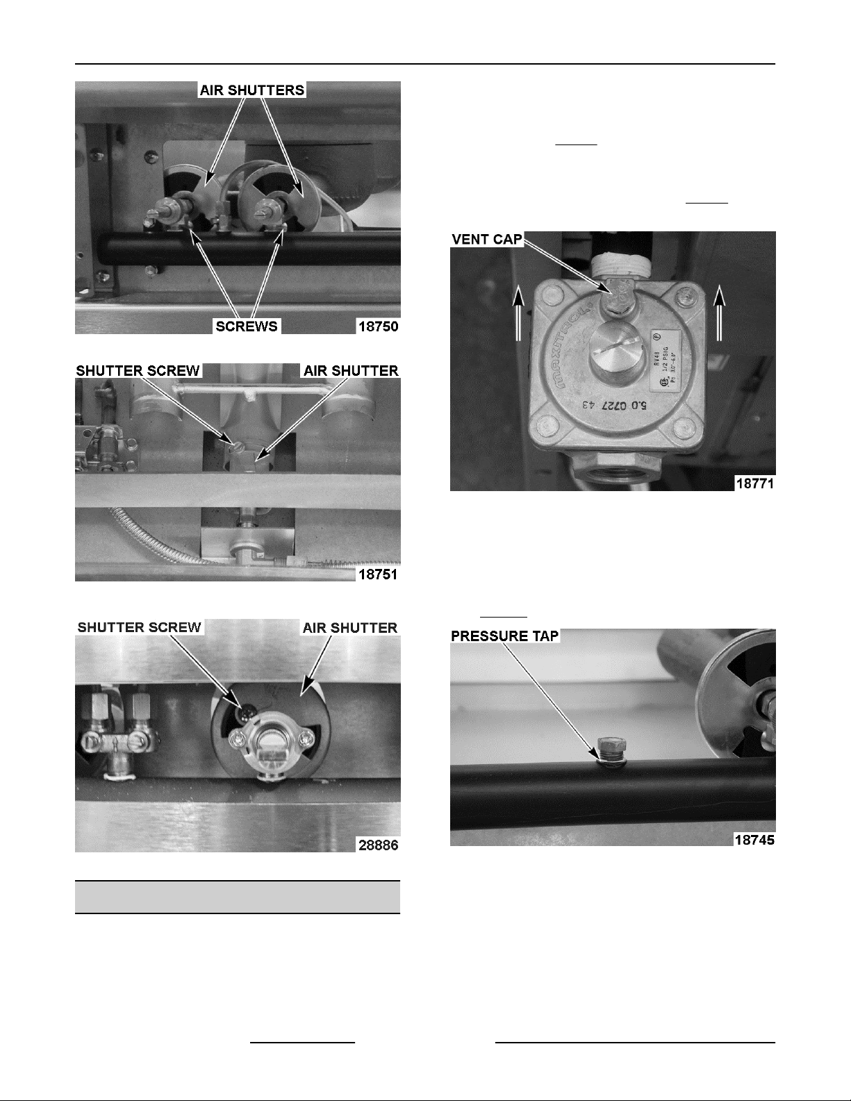
BURNER AIR SHUTTER
ADJUSTMENT
The efficiency of the burner depends on a delicate
balance between the air supply and volume of gas.
Whenever this balance is disturbed, poor operating
characteristics and excessive gas consumption may
occur. An air shutter on the front of the burner controls
the gas mixer balance. A yellow streaming flame on
the burner is an indication of insufficient primary air.
To correct this condition, loosen the shutter screw and
rotate the air shutter open until the flame begins to lift
from the burner, then close the shutter slightly and
tighten the shutter screw. A proper flame should be
blue in color, well-defined and seated on the burner
port. A white-blue flame is a result of excessive
primary air.
NOTE: The factory default air shutter positions are
half open natural; full open propane.
Page 27 of 38 F45471 Rev. A (0615)
Page 28
ENDURANCE / CHALLENGER MODULAR SERIES GAS RANGES - SERVICE PROCEDURES AND
ADJUSTMENTS
adjusted as necessary. Make sure the regulator is
mounted in the horizontal position with the arrow
pointing in the direction of gas flow. Clean vent cap
before adjusting. Fig. 66 shows gas flow direction and
vent cap location.
See unit data plate, riveted inside the kick panel, for
manifold pressure setting information. Fig. 67 shows
manifold pressure tap location.
Top Burner Air Shutters
Oven Burner Air Shutter
Charbroiler Burner Air Shutter
REGULATOR ADJUSTMENT
NOTE: Regulators come preset, but should be
checked anytime one is installed. Before adjusting
regulator, check incoming gas line pressure. Incoming
pressure must be 6-14" W.C. for natural gas and
11-14" W.C. for propane gas. If incoming pressure is
not correct, have the gas source checked and
Fig. 66
1. Connect manometer to either of the pressure
taps provided on the range gas piping between
the burner control valve sets. If pressure taps are
not available, install a pipe tee and hose barb
assembly on the outlet of the regulator. See
TOOLS.
Fig. 67
2. Open the valves to turn on approximately half of
the units burners to the full on position and check
manometer reading. The reading should be 5"
W.C. for natural gas and 10" W.C. for propane
gas. Tolerance is ±0.3" W.C.
3. If manifold pressure is not correct, adjust the
regulator as follows:
A. Remove the regulator closing nut.
F45471 Rev. A (0615) Page 28 of 38
Page 29

ENDURANCE / CHALLENGER MODULAR SERIES GAS RANGES - SERVICE PROCEDURES AND
ADJUSTMENTS
OVEN BURNER NOZZLE SHOWN
Fig. 68
STANDARD OVEN THERMOSTAT
B. Insert a flat edge screwdriver into the top of
regulator housing to reach the adjusting
screw. While watching the manometer, turn
the adjusting screw clockwise to increase
pressure and counterclockwise to decrease
pressure until the proper gas pressure is
achieved. See data plate.
C. Install the regulator closing nut.
D. Remove manometer from pressure tap.
E. Apply thread sealant to pressure tap plug
and reinstall. Thread sealant must be
insoluble in propane and natural gas.
BY-PASS FLAME ADJUSTMENT
NOTE: The bypass flame setting has a direct affect
on calibration, and must be verified prior to checking
or adjusting calibration of any "modulating
thermostat". The by-pass flame can be viewed
through the kick panel for adjustment.
1. Turn thermostat knob to 350°F.
2. Wait 15 minutes for oven to heat up.
3. Turn thermostat knob to lowest setting. DO NOT
TURN OFF.
4. Remove thermostat knob.
BURNER NOZZLE CHECK
5. With a small flat edge screwdriver, turn by-pass
The burner nozzle is mounted between the oven gas
supply tubing/mounting bracket and the u-burner
assembly. If burner operation seems poor and other
systems have been checked, access the burner for
the range section being serviced and remove the
burner nozzle.
• Check for blockage or damage.
flame adjustment screw counterclockwise to
increase by-pass flame or clockwise to decrease
flame until both legs of burner have
approximately 1/8" stable flame on each port.
Ports should be set to just above “flickering”.
NOTE: Some flickering of the flame is acceptable,
only in the bend of the burner.
• Verify gas orifice hood is correct for the altitude.
See SPECIFICATIONS for Orifice Size
Requirements.
Page 29 of 38 F45471 Rev. A (0615)
Fig. 70
Page 30
ENDURANCE / CHALLENGER MODULAR SERIES GAS RANGES - SERVICE PROCEDURES AND
ADJUSTMENTS
6. Replace thermostat knob.
A. Turn knob to 350°F and verify increase in
flame height on burner ports.
7. Turn knob back to lowest setting. Verify decrease
in by-pass flame height on burner ports and that
burner remains lit.
STANDARD OVEN THERMOSTAT
TEMPERATURE ADJUSTMENT
NOTE: Calibration on this "modulating thermostat"
version is made using the knob for temperature
adjustments and not the inner screw as on previous
versions.
1. Place a thermocouple type temperature probe
(type K preferred) in center of oven to verify
actual temperatures throughout adjustment.
2. Turn thermostat knob to 350°F. Wait 15 minutes
for oven to heat up.
3. Turn knob to the lowest setting and check the bypass flame for proper adjustment as outlined
under STANDARD OVEN THERMOSTAT BYPASS FLAME ADJUSTMENT.
4. Turn knob back to 350°F and wait for
temperature to stabilize (approximately 30
minutes). When the temperature stabilizes take
a temperature reading. If actual temperature is
more than 15°F from knob setting, calibrate as
follows:
5. Pull off thermostat knob.
6. Loosen two screws on the back of knob.
8. Tighten screws and replace knob.
9. Verify temperature setting at 400°F and 450°F.
Wait 15 minutes for oven to heat up at each
setting. If actual oven temperature is not within
15°F, readjust as outlined in this procedure. If
three consecutive adjustments do not produce
acceptable results, replace thermostat and verify
calibration.
CONVECTION OVEN
THERMOSTAT-COMBO VALVE
ADJUSTMENT
Operation
The "snap action" thermostat-combo valve is selfregulating and the thermostat is internally connected
to the valve. When thermostat dial is set to 350°F and
the oven is below setpoint, the valve opens to allow
gas flow and burner lights. As the oven temperature
rises, the pressure from the sensor bulb in the oven
increases. Fluid in the capillary tube expands with the
temperature increase and presses against a
diaphragm in the thermostat. When the oven
temperature reaches setpoint, the internal valve
closes to stop gas flow to burner.
When the oven temperature decreases below
setpoint, the pressure is reduced in the capillary which
reduces the force on the diaphragm allowing the valve
to open again.
Adjustment
1. Place a thermocouple temperature probe (type K
preferred) in center of oven to verify actual
temperatures throughout adjustment.
2. Turn power switch on.
3. Turn thermostat knob to 350°F and allow oven to
4. Take a temperature reading. If actual
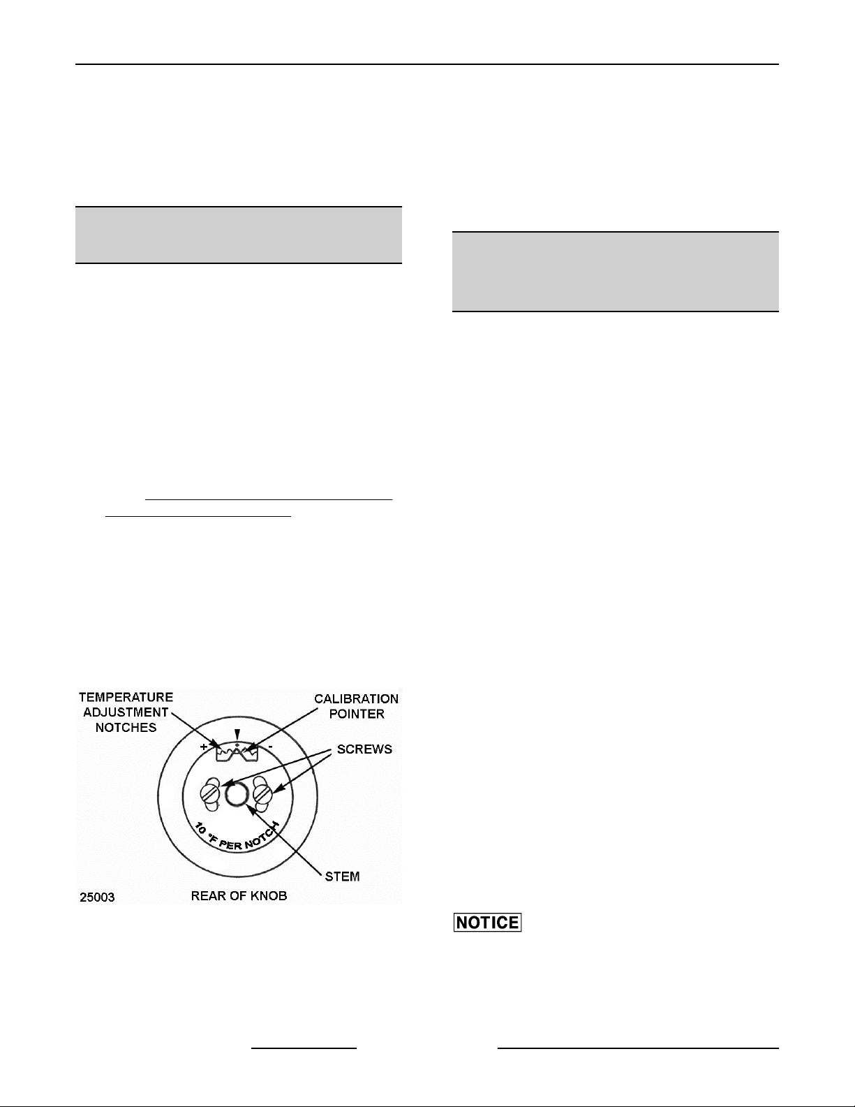
Fig. 71
7. Grasp stem and push it out from knob to clear the
temperature adjustment notches. Move
calibration pointer at base of stem clockwise to
lower temperature or counterclockwise to raise
temperature as close to the desired setpoint as
possible. Each notch equals 10°F.
F45471 Rev. A (0615) Page 30 of 38
than 3/8 turn or damage to the thermostat may occur.
cycle 3 complete times. If the customer has a
preferred temperature setting that they always
operate the oven at such as 325°, 375° or 400°,
you may calibrate to that temperature instead.
temperature is more than 20° from knob setting,
calibrate as follows:
A. Pull off knob. Do not rotate knob during
removal.
Do not turn the adjustment screw more
Page 31

ENDURANCE / CHALLENGER MODULAR SERIES GAS RANGES - SERVICE PROCEDURES AND
ADJUSTMENTS
B. While holding outer shaft in place, turn inner
screw using a small flat edge screwdriver
1/8 turn clockwise to decrease and
counterclockwise to increase. 1/4 turn =
35°F. See Fig. 72 below.
C. Verify temperature at 350°F (or customers
preferred setting). Allow oven to cycle 3
times.
NOTE: You must allow the oven to cycle 3 times to
stabilize oven temperature or the calibration
adjustment may be invalid.
D. Take a temperature reading. If temperature
is within acceptable limits, continue to next
step. If temperature is not within 20°F then
re-adjust as outlined in this procedure. If 3
consecutive adjustments do not produce
acceptable results, replace thermostat and
verify calibration.
E. Apply a small amount of a non permanent
type sealer (preferably fast drying) such as
nail polish or equivalent around the inner
screw head to prevent movement during
outer shaft rotation. Allow sufficient time for
the applied sealer to dry then install knob.
See TOOLS.
F. If calibrating at 350°F, verify temperature at
400°F. If calibrating at a customer preferred
temperature setting, select one temperature
setting above the customer preferred
setting. If the customers temperature setting
is 450F, then calibrate at that temp only.
Allow oven to cycle 3 times at the
temperature setting. If actual oven
temperature is not within 20°F of the setting,
replace thermostat and verify calibration.
GRIDDLE THERMOSTAT-COMBO
VALVE ADJUSTMENT
Operation
The "snap action thermostat-combo" valve is selfregulating and the thermostat is internally connected
to the valve. When thermostat dial is set to 350°F and
the griddle is below setpoint, the valve opens to allow
gas flow and burner lights. As the griddle temperature
rises, the pressure from the sensor bulb secured to
the bottom of the griddle plate increases. Fluid in the
capillary tube expands with the temperature increase
and presses against a diaphragm in the thermostat.
When the griddle temperature reaches setpoint, the
internal valve closes to stop gas flow to burner.
When the griddle temperature decreases below
setpoint, the pressure is reduced in the capillary which
reduces the force on the diaphragm allowing the valve
to open again.
Fig. 72
Adjustment
1. Place a thermocouple type surface temperature
probe (type K preferred) in center of griddle to
verify actual temperatures throughout
adjustment.
2. Turn thermostat knob to 350°F and allow griddle
to cycle 3 complete times. If the customer has a
preferred temperature setting that they always
operate the oven at such as 325°, 375° or 400°,
you may calibrate to that temperature instead.
3. Take a temperature reading. If actual
temperature is more than 20° from knob setting,
calibrate as follows:
A. Pull off knob. Do not rotate knob during
removal.
Do not turn the adjustment screw more
than 3/8 turn or damage to the thermostat may occur.
Page 31 of 38 F45471 Rev. A (0615)
Page 32

ENDURANCE / CHALLENGER MODULAR SERIES GAS RANGES - SERVICE PROCEDURES AND
ADJUSTMENTS
B. While holding outer shaft in place, turn inner
screw using a small flat edge screwdriver
1/8 turn clockwise to decrease and
counterclockwise to increase. 1/4 turn =
35°F. See picture Fig. 72 under
CONVECTION OVEN THERMOSTATCOMBO VALVE ADJUSTMENT.
C. Verify temperature setting at 350°F (or
customers preferred setting). Allow griddle
to cycle 3 times.
NOTE: You must allow the griddle to cycle 3 times to
stabilize oven temperature or the calibration
adjustment may be invalid.
D. Take a temperature reading. If temperature
is within acceptable limits, continue to next
step. If temperature is not within 20°F then
readjust as outlined in this procedure. If 3
consecutive adjustments do not produce
acceptable results, replace thermostat and
verify calibration.
E. Apply a small amount of a non permanent
type sealer (preferably fast drying) such as
nail polish or equivalent around the inner
screw head to prevent movement during
outer shaft rotation. Allow sufficient time for
the applied sealer to dry then install knob.
See TOOLS.
F. If calibrating at 350°F, verify temperature at
400°F. If calibrating at a customer preferred
temperature setting, select one temperature
setting above the customer preferred
setting. If the customers temperature setting
is 450F, then calibrate at that temp only.
Allow oven to cycle 3 times at the
temperature setting. If actual oven
temperature is not within 20°F of the setting,
replace thermostat and verify calibration.
THERMOCOUPLE TEST
Operation
The thermocouple supplies a DC millivolt signal (MV)
to the gas safety valve when heated by the pilot flame.
The gas safety valve will shut off gas flow to the pilot
and main burner in case of a pilot outage. When
energized by the thermocouple voltage, the gas safety
valve is held open to permit gas flow to the pilot and
provide gas for the burner when the oven thermostat
calls for heat. The pilot flame height is controlled by
an adjustable needle valve located under a small
cover screw on the gas safety valve.
Visually check pilot flame for the proper contact on
thermocouple and adjust as outlined under OVEN
PILOT FLAME HEIGHT. If adjustment does not result
in a pilot flame of proper height, then gas might not be
flowing properly to the pilot.
Check for:
• A plugged pilot orifice.
• Kinked or plugged pilot gas tubing.
• Low gas supply pressure.
Thermocouple Checks
NOTE: Tubing connection from the thermocouple tip
to gas safety valve is an electrical connection and
must be clean and dry. Do not use any sealing
compound on the threads of thermocouple nut.
Do not overtighten the thermocouple nut
or the insulator could be crushed, shorting the
thermocouple. Finger tighten the nut plus 1/4 turn with
a wrench only.
If pilot flame is correct and there are no excessive air
drafts in the room, then problem is either the
thermocouple output voltage or the gas safety valve.
Visually check the thermocouple tip (hot end) and tube
lead for:
• Loose thermocouple connection (electrical) at
the safety valve.
• Corrosion or debris on the threaded connector or
thermocouple tip causing a poor electrical
connection.
• Kinks or pinches that might cause a short
between the tube and the wire inside.
If thermocouple is loose, tighten mounting nut as
described above in NOTICE. If thermocouple
connection shows signs of corrosion or debris that
cannot be cleaned; or damage as described, replace
it and check pilot operation as outlined under
PILOT FLAME HEIGHT.
Thermocouple Test
Check the thermocouple output voltage (DC millivolts)
with a VOM as outlined in the steps below.
• If thermocouple adaptor (see TOOLS) is
available, check closed circuit voltage as outlined
in the test procedure.
• If thermocouple adaptor is not available, check
open circuit voltage as outlined in the test
procedure.
OVEN
Pilot Checks
If experiencing pilot outages, perform the following:
F45471 Rev. A (0615) Page 32 of 38
Page 33

ENDURANCE / CHALLENGER MODULAR SERIES GAS RANGES - SERVICE PROCEDURES AND
ADJUSTMENTS
• If a VOM is not available, replace the
thermocouple with a new one as outlined under
STANDARD OVEN PILOT ASSEMBLY AND
THERMOCOUPLE or CONVECTION OVEN
PILOT ASSEMBLY AND THERMOCOUPLE or
and check operation GRIDDLE PILOT
ASSEMBLY AND THERMOCOUPLE.
1. Disconnect thermocouple from gas safety valve.
2. Select the test to perform.
3. Closed Circuit.
A. Install thermocouple adaptor at the
threaded connection on gas safety valve.
B. Install thermocouple to the adaptor. Tighten
mounting nut as described above in
NOTICE.
C. Light the pilot. Allow pilot to heat
thermocouple for one to two minutes.
D. Connect one meter lead to the adaptor test
point and the other meter lead to the tube.
Compare reading to the value listed in the
table below.
4. Open Circuit
CHARBROILER PILOT
ADJUSTMENT
Pilot Adjustment
• Turn pilot adjustment screws clockwise to
decrease the flame.
• Turn pilot adjustment screws counter-clockwise
to increase the flame.
• Pilot is in adjustment when it will stay on
continually and lights the burner without delayed
ignition.
Fig. 73
A. Connect one meter lead to the tip of the
threaded end and the other meter lead to the
tube. Compare reading to the values listed
in the table below.
B. Light the pilot and continue to hold red
button down during this test. Allow pilot to
heat thermocouple for one to two minutes.
C. Compare reading to the value listed in the
table below.
THERMOCOUPLE MV READINGS
Closed Circuit Open Circuit
Range 8 to 25 MV 25 to 35 MV
5. If readings are less than the minimum stated
above, replace the thermocouple as outlined
under STANDARD OVEN PILOT ASSEMBLY
AND THERMOCOUPLE or CONVECTION
OVEN PILOT ASSEMBLY AND
THERMOCOUPLE or GRIDDLE PILOT
ASSEMBLY AND THERMOCOUPLE.
6. If pilot is still not functioning properly after
replacing thermocouple, then a problem exists in
the gas safety valve. Install a replacement GAS
SAFETY VALVE (STANDARD AND
CONVECTION OVENS) and check for proper
operation.
Page 33 of 38 F45471 Rev. A (0615)
Page 34

ENDURANCE / CHALLENGER MODULAR SERIES GAS RANGES - ELECTRICAL OPERATION
ELECTRICAL OPERATION
COMPONENT FUNCTION
Power Cord ........... Connects range to power source.
On/Off Switch ......... Provides power for the convection oven motor and solenoid valve.
Solenoid Valve ....... Allows gas flow to the convection oven burner assembly when solenoid is energized by
the door switch (normally closed valve).
Door Switch .......... Removes power from convection motor and solenoid valve when oven door is open (N.O.
- held closed).
Convection Oven
Motor (Single
Phase) ................
Junction Box ......... Connection point for electrical wires.
Circulates heated air inside the oven. The motor electrical power is routed through door
switch.
SEQUENCE OF OPERATION -
CONVECTION OVEN
Refer to AI3549 SCHEMATIC DIAGRAM CONVECTION OVENS.
Oven temperature is below set point of control.
Convection Oven
1. Conditions.
A. 120VAC to oven controls and is properely
grounded.
B. Power switch off.
C. Door switch held-closed (oven door closed).
D. Pilot lit.
E. Thermostat-combo valve is off.
F. Oven at room temperature.
2. Turn power switch on.
3. Set thermostat knob to 350°F.
4. Oven reaches setpoint temperature. Thermostat-
5. Door switch opened (oven door open).
6. Oven door closed. Door switch contacts close
7. Thermostat-combo valve cycles the burner as
B. Power to oven motor (blower circulates air
inside cavity).
A. Thermostat-combo valve calls for heat and
opens internal valve to allow gas flow to
burner.
B. Pilot lights the burner and heating begins.
combo valve closes internal valve to stop gas
flow to burner.
A. Power is removed from oven motor.
and oven motor resumes operation.
required to maintian setpoint temperature untill
thermostat knob is turned to off; or power switch
off.
A. Solenoid is energized allowing gas flow to
thermostat-combo valve.
F45471 Rev. A (0615) Page 34 of 38
Page 35

ENDURANCE / CHALLENGER MODULAR SERIES GAS RANGES - ELECTRICAL OPERATION
SCHEMATIC DIAGRAM - CONVECTION OVENS
Fig. 74
Page 35 of 38 F45471 Rev. A (0615)
Page 36

ENDURANCE / CHALLENGER MODULAR SERIES GAS RANGES - ELECTRICAL OPERATION
WIRING DIAGRAM - CONVECTION OVENS
Fig. 75
F45471 Rev. A (0615) Page 36 of 38
Page 37

ENDURANCE / CHALLENGER MODULAR SERIES GAS RANGES - TROUBLESHOOTING
TROUBLESHOOTING
TROUBLESHOOTING
GENERAL
SYMPTOM POSSIBLE CAUSE
1. Incorrect gas pressure.
2. Pilot burner not adjusted properly.
3. Pilot burner blocked.
Pilot does not remain lit.
Burner flame too yellow
Slow to heat or not hot enough.
Oven temperature too hot.
Low burner flame (all burners).
Low burner flame (individual burner). 1. Air mixture incorrect.
Flame floats on burner.
4. Thermocouple not positioned correctly or
malfunctioning.
5. Gas safety valve malfunction.
6. Incorrect oven pilot orifice.
7. Ventilation issue in room (drafts blowing out pilot).
1. Orifice incorrect size or dirty.
2. Air shutter not adjusted correctly or dirty.
3. Incorrect gas pressure.
4. Incorrect gas type.
5. Orifice misaligned in venturi.
6. Appliance not venting properly.
1. Low gas pressure.
2. Thermostat out of calibration.
1. Thermostat out of calibration.
2. By-pass flame to high.
1. Low gas pressure.
2. Incorrect gas type.
1. Inadequate air supply.
2. Restricted exhaust flue (ovens).
CONVECTION OVENS ONLY
SYMPTOM POSSIBLE CAUSE
Oven temperature too hot. 1. Thermostat out of calibration.
Page 37 of 38 F45471 Rev. A (0615)
Page 38

ENDURANCE / CHALLENGER MODULAR SERIES GAS RANGES - TROUBLESHOOTING
SYMPTOM POSSIBLE CAUSE
Convection motor does not operate.
Convection motor noisy.
CONVECTION OVENS ONLY
1. Main power supply not on.
2. Incorrect voltage.
3. Oven door switch arm not engaging door hinge arm
properely.
4. Oven door switch open or inoperative.
5. Power switch open or inoperative.
6. Convection motor inoperative.
1. Motor mounting bracket or motor mounting plate to
the back of the chassis is loose.
2. Fan shroud is loose or fan is rubbing shroud.
3. Fan loose on motor shaft.
4. Fan excessively dirty or debris stuck in fan.
5. Motor malfunction.
1. Low gas pressure.
Pilot does not remain lit (no gas flow to oven burner).
2. Thermocouple not positioned correctly or
malfunctioning.
3. Solenoid malfunction.
4. Pilot gas flow too low. Adjust on gas safety valve.
F45471 Rev. A (0615) Page 38 of 38
 Loading...