

Page 1
Instruction Manual
Manual de instrucciones
ITEM NO. 019-4274
ARTICULO No. OFNC1590 000-0000
v070820
15
o
Framing Coil Nailer
Page 2
2
THANK YOU for your purchase of this Vulcan Air Tool. With proper care and
use you can expect your purchase to provide years of trouble free service!
SHOULD YOU HAVE A QUESTION OR A PROBLEM WITH YOUR
VULCAN TOOL, PLEASE CALL OUR CUSTOMER SERVICE
DEPARTMENT TOLL FREE AT:
1-800-482-0131
Please have the tool, model number and instruction manual at hand before calling.
ONE YEAR LIMITED CONSUMER WARRANTY
If you have a question or should you have a problem with any Vulcan Air Tool, call
the Vulcan Customer Service line at 1-800-482-0131.
This product is warranted to be free from defects to material and workmanship
for a period of ONE YEAR from date of purchase. If defective the product will be
repaired or replaced. Call the Vulcan Power Tool customer service line at 1-800-
482-0131 and a customer representative will attempt to help resolve any issue. If
directed by a representative, return the product along with proof of purchase to
your dealer. Normal wear, damage due to abuse or mishandling or unauthorized
repair is not covered. This warranty does not apply to accessories. This warranty
gives you specic legal rights that vary from state to state.
This tool is intended for consumer use and is not a commercial tool. In the event
the tool is used commercially, the warranty should be for a period of 30 days.
VULCAN AIR TOOLS ARE MADE EXCLUSIVELY FOR:
Memphis, TN 38101
Page 3

3
SAFETY RULES FOR ALL TOOLS
Read and understand all instructions. Failure to follow all instructions listed
below may result in serious personal injury.
SAVE THESE INSTRUCTIONS
WARNING
!
Work Area
Keep work area clean and well lit. Cluttered
benches and dark areas invite accidents.
Keep by-standers, children, and visitors away
while using your tool. All children should be kept
away from the work area. Don’t let them handle
machines, tools or extension cords. Visitors can
be a distraction and are difcult to protect from
injury. Distractions can cause you to lose control.
Personal Safety
Stay alert. Watch what you are doing & use
common sense. Keep hands and body away from
the path of any potential red fastener. Do not
operate any tool when you are tired, under the
inuence of drugs, alcohol, or medication. A
moment of inattention while operating this tool
may result in serious injury.
Dress properly. Do not wear loose clothing
or jewelry; they can be caught in moving parts.
Protective, non-electrically conductive gloves
and non-skid footwear are recommended when
working. Wear protective hair covering to contain
long hair and keep it from harm. Keep hands dry,
clean and free from oil and grease.
Safety glasses To prevent eye injuries, the tool
operator and all persons in the work area must
wear ANSI Z87.1 approved safety glasses with
permanently attached, rigid side shields.
Hearing protection. Wear ear protection to
safeguard against possible hearing loss.
Guard against electric shock. Prevent body
contact with grounded surfaces: pipes, radiators,
ranges, and refrigerator enclosures. Before
driving fasteners into walls, oors, or wherever
“live” electrical wires may be encountered, try to
ascertain whether there is a danger of shock.
Do not overreach. Keep proper footing and
balance at all times. Do not reach over or across
machines which are running.
Employers must enforce compliance with the
safety warnings and all other instructions
in this manual. Keep it available for use by
everyone assigned to use this tool. Permit only
trained and experienced workers to operate
pneumatic fastening tools.
Tool Use and Care
Use clamps or other practical way to secure
and support the workpiece to a stable
platform. Holding the work by hand or against
your body is unstable and may lead to loss of
control.
Store idle equipment. Store equipment in a dry
area to inhibit rust. Equipment also should be in
a high location or locked up to keep out of reach
of children.
Don’t force the tool. It will do the job better and
more safely at the rate for which it was intended.
Use the right tool. Don’t force a small tool or
attachment to do the work of a larger industrial
tool. Don’t use a tool for a purpose for which it
was not intended
Extension cords. Observe warnings that
accompany air compressors concerning the use of
correct gauge and and concerning insulation for
outdoor use.
Service
Check for damaged parts. Before using this
tool, any part that is damaged should be carefully
checked to determine that it will operate properly
and perform its intended function. Check for
alignment of moving parts, binding of moving
parts, breakage of parts, mountings, and other
conditions that may affect its operation. Inspect
screws and tighten any ones that are loose. Any
part that is damaged should be properly repaired
or replaced by an authorized service center unless
otherwise indicated elsewhere in the instruction
manual. Have defective switches replaced by an
authorized service center. Don’t use the tool if
Page 4

4
switch does not turn it on and off properly.
User service. Some user-serviceable components
are described in the Troubleshooting section. We
cannot guarantee repairs made or attempted by
anyone other than authorized agencies.
Tool service must be performed only by
qualied repair personnel. Service or
maintenance performed by unqualied personnel
could result in risk of injury. For example, internal
wires may be misplaced or pinched, safety guard
Guard against electric shock. Prevent body
contact with grounded surfaces: pipes, radiators,
ranges, and refrigerator enclosures. Before
driving fasteners into walls, oors, or wherever
“live” electrical wires may be encountered, try to
ascertain whether there is a danger of shock.
Hearing protection. Wear ear protection when
using the tool for extended periods. Prolonged
exposure to high intensity noise can cause
hearing loss.
Safety glasses To prevent eye injuries, the tool
operator and all persons in the work area must
wear approved safety glasses conforming to ANSI
Z87.1 specications with permanently attached,
rigid side shields.
Use clean, dry, regulated, compressed air at 70
to 120 psi.
Do not connect tool to pressure which
potentially exceeds 200 psi.
Air hose. Only use hose that is rated for a
minimum working pressure of 150 psi or 150%
of the maximum system pressure, whichever is
greater.
Never use oxygen, carbon dioxide, combustible
gases or any other bottled gas as a power
source for this tool. Explosion and serious
personal injury could result.
Couplings. Connect tool to the air supply hose
with 1/4” NPT couplings that remove all pressure
from the tool when the coupling is disconnnected.
Be aware of air hoses and their connections.
Don’t trip over hoses. Make sure all connections
are tight.
Disconnect tool from air supply hose before
return springs may be improperly mounted.
When servicing tool, use only identical
replacement parts. Follow instructions in
the Maintenance section of this manual. Use
of unauthorized parts or failure to follow
Maintenance instructions may create a risk of
injury. Certain cleaning agents such as gasoline,
carbon tetrachloride, ammonia, etc. may damage
plastic parts.
SAFETY RULES FOR AIR NAILERS
doing any disassembly, maintenance, loading
fasteners, clearing a jammed fastener, leaving
the work area, moving the tool to another
location, or handing the tool to another person.
Never use a tool that is leaking air, has missing
or damaged parts, or requires repair. Before
each use, make sure all screws and caps are
securely tightened.
Check for damaged parts. Never use a tool if
safety, trigger, or spring are inoperable, missing or
damaged. Do not alter or remove safety, trigger,
or springs. Make daily inspections for the free
movement of trigger and safety mechanism.
Replacement parts. When servicing, use
only identical replacement parts and fasteners
recommended by us.
Be sure the tool is disconnected from the air
supply before loading the fasteners. Take
care on re-connection: fasteners may be red
accidentally during connection. The fastener
driving mechanism may cycle when the tool is
connected to the air supply.
Assume the tool contains fasteners at all times.
Always keep it pointed away from yourself and
others. No horseplay. Respect the tool as having
lethal potential.
Do not load fasteners with trigger or safety
depressed. The tool may unintentionally re a
fastener.
Do not depress the trigger unless the nosepiece
is directed at the worksurface or when not
driving fasteners. Never carry tool with nger on
or touching the trigger mechanism: tool may re
an unwanted fastener.
Page 5

5
The warnings, cautions, and instructions detailed in this manual cannot cover all
possible conditions and situations that occur. It must be understood by the operator
that COMMON SENSE AND CAUTION ARE FACTORS that cannot be built into
this product, but MUST BE SUPPLIED BY THE OPERATOR.
Fire fasteners into work surface only and never
into materials too hard to penetrate
Grip tool rmly to maintain control while
allowing the tool to recoil away from the work
surface as the fastener is driven. If the safety is
allowed to recontact the work surface before the
trigger is released, an unwanted fastener will be
red.
Do not drive fasteners on top of other
fasteners, or with the tool at too steep an angle:
the fasteners can ricochet causing personal injury.
Do not drive fasteners too close to the edge
of the workpiece. The workpiece is likely to
split, allowing the fasteners to y free or ricochet
causing personal injury.
WARNING
!
Page 6
6
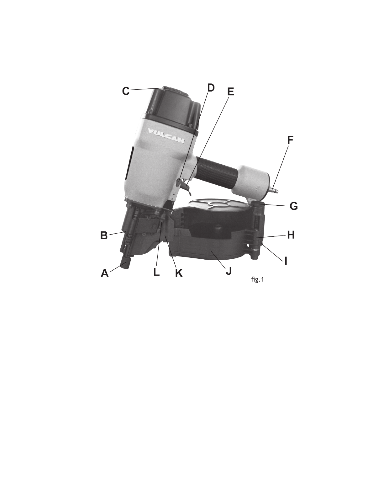
Nomenclature for No. 019-4274
15o Framing Coil Nailer
KEY
A) Contact tip
B) Depth adjustment knob
C) 360 degree re-directable exhaust port
D) Trigger mode selector
E) Trigger
F) Male quick-connect tting
SPECIFICATIONS
= Operating pressure: 70 - 120 psi (max. 120 psi)
= Air consumption: 0.17 cu. ft. / cycle @ 100 psi
= Air Inlet: 1/4” NPT
= Weight: 8.2 lbs
= Pkg. weight: 15.4 lbs
G) Magazine height adjustment knob
H) Magazine height indicator
I) Magazine height scale
J) Lower magazine
K) Feed cover plate
L) Cover plate latch
g.1
Page 7

7
OPERATION AND USE INSTRUCTIONS
WARNING
!
BE SURE THAT YOU READ, UNDERSTAND
AND FOLLOW THE SAFETY RULES THAT ACCOMPANY THIS
MANUAL. THIS WILL ALLOW FOR BEST USE AND MAXIMUM
USER SATISFACTION.
The Vulcan Model 019-4274 is a light duty, coil fed, pneumatic nailer, using
compressed air as a power source. It is designed to install 2”– 3-9/16”, 11-1/2 ga.
to 10-1/4 ga. spiral, ring or smooth wire-collated nails with a collation angle of 15
degrees. The tool is made with a magnesium alloy body and cylinder cap to provide
light weight while maintaining high strength and rigidity.
POWER SOURCE
This tool is designed to operate on clean, dry, compressed air at regulated
pressures between 70 - 120 psi (max. 120 psi). The preferred system would include
a lter, a pressure regulator, and an automatic oiler located as close to the tool as
possible. (Within 15 ft. is ideal). All compressed air contains moisture and other
contaminates that are detrimental to internal components of the tool. An airline lter
will remove most of these contaminates and signicantly prolong the life of the tool.
If an in-line oiler is not available: place 5 or 6 drops of oil into the tool’s air inlet at
the beginning of each workday.
Nailer
Air hose
Regulator
Oiler
Filter
Air Supply
CAUTION
!
= All line components (hoses, connectors, lters, regulators, etc.) must meet
150% of the maximum system pressure. Please try to use a hose of ID 3/8”
connecting nailer with compressor.
= Do not connect this tool to a system with maximum potential pressure greater
than 180 psi.
= Disconnect your air line from your nailer using the quick connect on the air
hose. Do not unscrew the air inlet from the nailer with your air hose connected.
= Disconnect tool from air supply before loading fasteners, performing mainte-
nance, clearing a jammed fastener, leaving work area, moving tool to another
location, or handing the tool to another person.
Page 8

8
3. Open cover plate (K, g.4)
4. Open the lower magazine (
J, g.1).
5. Place a coil of nails in the lower magazine.
6. Rotate magzine height adjustment knob (
G, g.5)
to adjust the lower magazine according to the nails’
length. The highest position is used for 2” nails
while the lowest position is used for 3-9/16” nails.
For all nails between minimum and maximum,
adjust the lower magzine accordingly.
7. Close the lower magazine.
2.
Depress cover-plate latch (L, g.3)
CAUTION
!
= Disconnect the tool from the air supply.
= Keep tool pointed away from yourself and others at all times.
= Be sure the tool has an empty magazine when connecting to the air supply
= Do not load fasteners with trigger or safety pressed.
= Always wear approved safety glasses, and hearing protection when preparing
or operating the tool.
LOADING FASTENERS
1. After reading and understanding this entire manual,
Page 9

9
USING THE TOOL
Complete all steps as indicated in LOADING FASTENERS before use.
This tool can be red in two different ways:
1.
Sequential Fire:
= Turn the trigger mode selector (D, g.1) so the tail of selector is up.(g.6)
= Put the contact tip (A, g.1) of the tool on the working surface
= Lightly push the tool toward the working surface until the safety bracket is
depressed
= Press the trigger (E, g.1) to drive the fasteners. This “trigger re” method
provides the most accurate fastener placement.
2.
Bump Fire:
= Turn the trigger mode selector (D, g.1) so the tail
of selector is down.(g.6)
= Hold the contact tip (A, g.1) off the surface
= Press the trigger
= Keeping the trigger pressed, push the contact tip
(A, g.1) of the safety bracket against the working surface. Once the bracket is pushed back
enough, the nail will re.
= Original factory setting is single sequential re mode.
= READ and UNDERSTAND this operating manual before changing trigger
mode. Improper use may result in serious injury.
= Manufacturer assumes no responsibility for any injuries and loss caused by
improper use of the tool.
8. Draw the nails out and position the second nail on to the feed hook (
M, g.4).
9. Close cover-plate and latch (
L, g.3).
10. Rotate the directional exhaust deector (
C, g.1), so that the exhaust air blast
will be directed away from the operator.
11. Re-connect the tool to the air supply, being careful to aim the nosepiece
in a safe direction, and careful to avoid touching the trigger or the safety
mechanism. This is to prevent harm from fasteners accidentally discharging
should the fastener driving mechanism cycle when the tool is connected to the
air supply.
12. The tool is ready to operate.
IMPORTANT
!
Page 10

10
CLEARING A JAMMED FASTENER
CAUTION
!
Disconnect the tool from the air supply.
1. Open latch
2. Rotate lower magazine
3. Remove the nails from the magzine.
4. Use a slender; soft steel rod to drive the drive blade to its uppermost position.
5. Use a pair of needle nose pliers to remove the jammed fastener.
FASTENER DEPTH
Driving depth can be adjusted by rotating the depth adjustment knob (B, g.1).
=Test re a fastener into a scrap work piece and check
depth.
=If the nail is driven too deep, rotate the knob (B, g.7)
clockwise (when tool is upside-down) to move the
safety bracket downward.
=If a greater depth is desired, rotate the knob counter
clockwise to adjust the safety bracket upward.
=Test re another fastener in a scrap work piece and
check the depth.
=REPEAT AS NECESSARY UNTIL DESIRED DEPTH
IS ACHIEVED. The amount of air pressure required will
vary depending on the setting.
=Determine the lowest setting that will consistently
perform the job at hand. Air pressure in excess of that
required can cause premature wear and/or damage to
the tool.
CAUTION
!
= Disconnect tool from air supply before loading fasteners, performing
maintenance, clearing a jammed fastener, leaving working area, moving tool to
another location or handing the tool to another person.
= Clean and inspect tool daily. Carefully check for proper operation of trigger and
safety mechanism.
= Do not use the tool unless both the trigger and the safety mechanism are
functional.
= Do not use the tool if its leaking air or needs any other repair.
Page 11

11
MAINTENANCE
CAUTION
!
Disconnect the tool from the air supply before cleaning and
inspecting the tool. Correct all problems before operating.
CLEAN AND INSPECT DAILY
= Add pneumatic tool oil into the oiler regularly to assure that all moving.
Frequent, but not excessive lubrication is required for the best performance.
Oil added through the air line connection will lubricate the inside parts. An
automatic oiler is recommended, but 2 drops of oil may be added manually into
the tool’s air intake at the male quick-connect tting (F, g.1) at the beginning
of each workday and after about every hour of continuous use. Only a few
drops at a time are necessary. More than this will pool inside the tool and be
expelled from the tool’s exhaust during ring. USE ONLY PNEUMATIC TOOL
OIL. Do not use detergent oil or oil with other additives, as these can cause
accelerated wear on the seals.
= Check the lter of the compressor weekly. Open drain cock to drain all water
and contaminants out of the air tank.
= Wipe the tool clean.
= Blow the tool clean using high compressed air, and then use non-ammable
cleaning solutions to wipe exterior of tool if necessary.
= Do not soak tool in cleaning solutions. Such solutions can damage internal
parts. The exposed portion of the small piston rod and feed hook must be kept
clean.
= Inspect trigger and safety mechanism daily to assure system is complete and
functional.
= Keep all screws tight. Loose screws can cause personal injury or damage to
the tool. Check if there are worn and damaged parts. If any, please replace
immediately.
CAUTION
!
=Keep the tool pointed away from yourself and others at all times.
=Always connect the tool to air supply before loading fasteners.
=Do not load fasteners with safety or trigger depressed.
=Always wear approved safety glasses and hearing protection when preparing
or operating this tool.
=Never use a tool that leaks air or needs repair.
Page 12

12
PROBLEM CAUSE SOLUTION
Air leaking at
trigger area
O-ring in trigger valve stem is
worn and damaged.
Check/replace O-ring &
lubricate
O-ring in trigger valve head is
worn or damaged
Check/replace O-ring &
lubricate
Contains foreigh matter Clean the tool & lubricate
Air leaking from
the lower body
and the nose
Screw is loose at connection
between nose and body
Tighten screw & re-check
O-ring is damaged between
body and nose
Check/replace O-ring &
lubricate
Bumper is damaged Replace the bumper
Foreign matter at the contact
between bumper and body
Disassemble & clean
Air leaking from
the upper body
and the nose
Screw is loose at connection
between cylinder and body
Tighten screw & re-check
O-ring is damaged Check/replace O-ring &
lubricate
Gasket is damaged Replace the gasket
TROUBLESHOOTING
TROUBLESHOOTING
WARNING
!
Stop using the tool immediately if any of the following problems occur.
Serious personal injury may result. Any repairs or replacements must be done
by qualied personnel or by an authorized service centre only.
CAUTION
!
= Disconnect the tool from air supply before performing any service procedure.
= When inserting new or re-installing O-rings, make sure they are clean and
lubricated with an O-ring lubricant.
Page 13

13
PROBLEM CAUSE SOLUTION
Failure to start tool Tool dry, lack of lubrication Use pneumatic tool oil
Spring in the cylinder cap is
damaged
Replace spring in the
cylinder cap
Valve sticks to cylinder cap Disassemble, clean &
lubricate
Blade driving
fasteners too
deeply
Safety bracket position is
incorrect
Rotate depth adjustment
know to move the safety
bracket down
Air pressure is too high Decrease air pressure
Tool skips
fasteners, feeds
intermittently
Foreign matter between
the small piston and small
cylinderDamaged pusher spring
Disassemble, clean &
lubricate
O-ring on the small piston is
worn and damaged
Check/replace O-ring &
lubricate
Tool dry, lack of lubrication Use pneumatic tool oil
Spring on the small piston is
damaged
Replace small spring
Air pressure too low Increase air pressure, but
don’t exceed120 psi
Body/nose connecting screw is
loose
Tighten all screws
Stop hook can’t stop fasteners Replace the taper spring on
the stop hook
Bent fasteners Use recommended fasteners
Wrong size fasteners Use recommended fasteners
Gasket is damaged Replace gasket/tighten
screw
Small piston is dry Open nail housing, place
several drops of pneumatic
tool oil into the end cover
hole of the small piston
TROUBLESHOOTING
Page 14

14
PROBLEM CAUSE SOLUTION
Small piston bumper is worn
and damaged
Replace bumper and
lubricate small piston
Feed hook is binding Clean feed hook and torsion
spring
Nail length does not correspond
with height setting on lower
magazine
Adjust magazine height
adjusting knob on the lower
magazine
Weld-wires in nail coil broken Discard coil
Runs slowly or
has power loss
Tool dry, lack of lubrication Use pneumatic tool oil
Spring in cylinder cap damaged Replace spring in the
cylinder cap
Foreign matter between the
piston assembly and cylinder
Disassemble, clean &
lubricate
Cylinder is not assembled to
home position
Reassemble after
disassembling
O-ring on the valve is dry after
disassembly
Lubricate and reassemble
Air pressure too low Increase air pressure, but
don’t exceed 120 psi
Driver is worn Replace the piston assembly
Inner diameter of hose is too
small
Use larger diameter hose
(3/8” minimum)
Fastener are
jammed
Fasteners are wrong size Use recommended fasteners
Weld-wires in nail coil broken Discard coil
Other Contact technical support
1-800-482-0131
TROUBLESHOOTING
Page 15

15
PARTS LIST
Please refer to the schematic drawing on page 17
No. DESCRIPTION
1 Screw
2 Spring Washer
3 Bushing
4 Exhaust Cover
5 Seal
6 Screw
7 Spring Washer
8 Cylinder Cap
9 Gasket
10 Washer
11 Valve Seat
12 Spring
13 O-Ring 57.5 X 2.6
14 O-Ring 72.4 X 3.5
15 Valve
16 Screw
17 Cylinder Seal
18 Collar
19 O-Ring 58 X 4.5
20 Piston Assembly
21 Cylinder
22 O-Ring 70.4 X3.5
23 O-Ring 67 X 3
24 Restrictive Seal
25 O-Ring 97.5 X 3.5
26 Bumper
27 Bumper
28 Body
No. DESCRIPTION
29 O-Ring
30 Guide Washer
31 Nose
32 Spring Washer
33 Screw
34 Spring
35 Bracket Assembly
36 Adjuster
37 Safetey Bracket
38 Spring Pin
39 Guide Safe
40 O-Ring 8.3 X 1.8
41 O-Ring 20.3 X 2.5
42 O-Ring 20.3 X 1.5
43 Valve Set
44 O-Ring 9.5 X 1.9
45 O-Ring 10.3 X 1.9
46 Trigger Valve Head
47 O-Ring 12.8 X 1.9
48 Spring
49 O-Ring 5.5 X 1.5
50 Trigger Valve Stem
51 O-Ring 24.8 X 2
52 Trigger Valve Guide
53 Spring
54 Trigger Assembly
55 Rotating Shaft Pin
56 Rotating Shaft Bushing
Page 16

16
PARTS LIST
Please refer to the schematic drawing on page 17
WARNING
!
Repairs should be made by an authorized repair centre.
Opening this tool could invalidate your warranty.
No. DESCRIPTION
57 Locking Washer
58 Steel Ball
59 Spring
60 Washer
61 Locking Washer
62 Cover
63 Spring
64 Piston Bumber
65 O-Ring 28.3 X 3
66 Piston
67 Torsion Spring
68 Pin
69 Feed Hook
70 O-Ring 14.3 X 2.5
71 Screw
72 Pin
73 Plate
74 Protector
75 Protector
76 Pin
77 Stop Hook
78 Taper Spring
79 Screw
No. DESCRIPTION
80 Spring Washer
81 Block Plate
82 Sping
83 Pin
84 Spring Pin
85 Handle
86 Nut
87 Washer
88 Pin
89 Lower Nail Housing
90 Seal
91 Adjusting Stem
92 Adjusting Bushing
93 Seal
94 Upper Nail Housing
95 Adjusting Nut
96 Screw
97 Screw
98 Soft Grip Sleeve
99 O-Ring 65.4 X 2.5
100 End Cap
101 Air Plug
Page 17

17
SCHEMATIC DRAWING
 Loading...