

Vulcan Fitness vfb12 Service Manual
SERVICE MANUAL
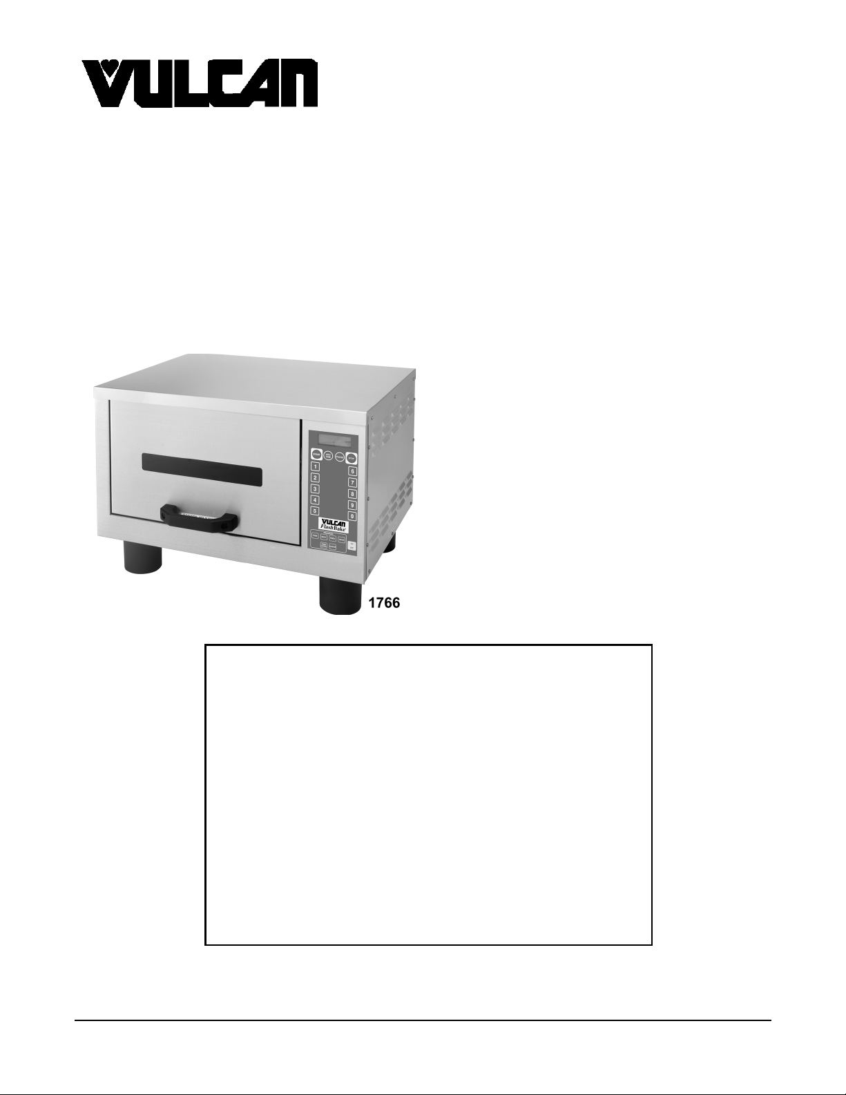
VFB12
Flash
Bake
®
OVEN
ML-114905 W/O CORD
ML-114908 W/CORD
- NOTICE This Manual is prepared for the use of trained Vulcan Service
Technicians and should not be used by those not properly
qu alif ied. If yo u have attend ed a Vulcan Service School for this
product, you may be qualified to perform all the procedures
described in this manual.
Thi s manu al i s no t i nten ded to be al l en comp assi ng . I f you have
not attende d a Vulcan S ervic e School for this produ ct , you should
read, in its entirety, the repair procedure you wish to perform to
determine if you have the necessary tools, instruments and skills
required to perform the procedure. Procedures for which you do
not have th e n ecessary too ls, in strument s and skills should be
performed b y a trained Vu lcan Service Technician.
Reproduction or other use of this Manual, without the express
written consent of Vulcan-Hart , is prohibited.
A Product of VULCAN-HART LOUISVILLE , KY. 40201-0696
Form 24586 ( 4/97)

FlashBake OVEN
TABLE OF CONTENTS
GENERAL............................................................................. 3
Introduction .................................................................. 3
Specifications ................................................................ 3
Tools....................................................................... 5
Lubrication .................................................................. 5
REMOVAL AND REPLACEMENT OF PARTS ................................................. 6
Covers And Panels ............................................................ 6
Ov en Cavity Panels ............................................................ 7
Door ....................................................................... 8
Door Gasket ................................................................. 8
Lamp Shields ................................................................ 9
Pulley Plate Assembly.......................................................... 9
High Limit Thermostat......................................................... 10
Door Springs ................................................................ 10
Exhaust Bl ower .............................................................. 11
Display .................................................................... 12
Keypad .................................................................... 12
Rack Drive Motor And Bushing .................................................. 12
Upper Lamp Shi eld Switch ..................................................... 13
Fuse ...................................................................... 13
Door Lock Solenoid ........................................................... 14
Thermistor (Front & Rear) ...................................................... 14
Photo Detector (Bottom & Top) .................................................. 14
Lamps..................................................................... 15
Lamp Socket ................................................................ 16
Relay Board ................................................................ 16
Control Board ............................................................... 17
Control Board Proms.......................................................... 17
SERVICE PROCEDURES AND ADJUSTMENTS .............................................. 18
Photo Detector Test........................................................... 18
Control Board Test Leds ....................................................... 18
Control Board Bypass ......................................................... 18
Lamp Test.................................................................. 18
Control Board Test ........................................................... 19
Voltage Test ................................................................ 20
Manual Voltage Det ect ion Over-ride .............................................. 20
Clearing Memory............................................................. 21
Alarm s And Diagnostics ........................................................ 22
ELECTRICAL OPERATION .............................................................. 23
Component Func tion .......................................................... 23
Component Locat ion .......................................................... 24
Sequence of O per ation ........................................................ 25
Wiring Diagram .............................................................. 27
TROUBLESHOOTING .................................................................. 28
© Vulcan 1997
2
FlashBake OVEN - GENERAL
GENERAL
INTRODUCTION
General
®
The Flash
employs a revolutionary high quality, high speed
cooking technology. The baking process is so fast that
food retai ns i ts natural j ui ces. B r ead products brown
and become cri sp while vegetabl es retai n t heir c ol or
and textur e. The t exture, appear ance and quality of
food cooked i n thi s o ve n i s superior to t hat provided
by any other method of cook ing.
In conventional ovens, the cooking process occurs by
transferr ing heat energy from t he ai r i nside t he ov e n
into the food. Hot surfaces inside the oven also
transfer heat di re ct ly i nto the f ood by conduc tion. In
convection ovens, the air-to-food heat transfer is
enhanced by the uniform circulation of the heated air
around the food. Forced air ovens blow the heated air
directly onto the food, providing marginal increases in
cooking speeds.
Flash
to cook by radiative heat transfer. The infrared energy
browns the surface of the f ood, while the visible li ght
energy penetrates and heats i t i nternally. Using the
proper combination of visible and infrared light
energy, the Flash
speed baking and high-quality food.
Bake
oven is a versatile oven that
Bake
ovens use visible and infrared light energy
Bake
oven provides efficient, high-
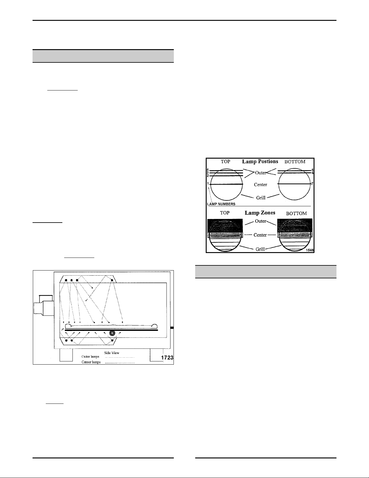
Zone Power Levels
The lamps are positioned so tha t th e center lamps are
above and below the center of the grill. The outer
lamps are l ocat ed abov e and below the rear of t he
grill. There is only one top center lamp and one
bottom c enter lamp. The top outer has three lam ps
and the bottom outer has two lamps.
Changing the top outer and bottom outer power levels
will have a greater effect on cooking times and
browning than changing the center power levels. This
is because outer intensities contain 70% of the
cooking energy while the center intensities only
contain 30% of the cooki ng ener gy .
• Use metal pans (thin wall pans will warp),
Corning Vision War e
• Do not
use paper (it will burn), Pyrex® dishes or
plastic.
®
or foil.
SPECIFICATIONS
General
• If the inlet air is obstruc te d or heated the ov en
will not operate properly.
• Install the HFB12 oven on a level counter top or
other stable surface of sufficient strength to
safely support the oven.
• Position the oven at an appropriate height to
allow safe handl ing o f h ot food and c onv enient
access to the oven controls.
• Position the oven so t hat the open door does not
extend i nto areas that may resul t in acc idental
contact wit h hot oven parts.
• The oven can be ordered with a 6' power cord for
receptacle i nstal l ati on. If t hi s i s the case assure
that t he unit cor d can be pl ugged int o the out l et
without strai n on the cord or plug.
3
FlashBake OVEN - GENERAL
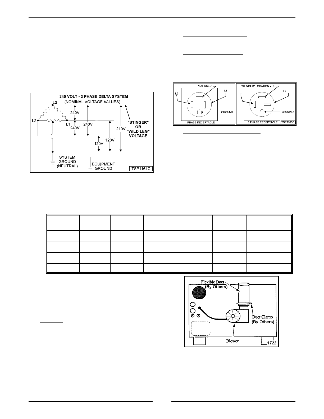
Electrical
NOTE:
Throughout this manual the term “STINGER”
(sometimes called “Wild Leg ”) will be use d to identify
the leg of a three phase system that shows more than
approxim ately 120 vol ts to system ground ( neutral).
The “Stinger” leg of a 240 volt 3 phase system can be
easily identified using a voltmeter. The line-to-ground
vol tage of t he “Stinger” will read approxi mately 210
volts. The line-to-ground voltage of the other two legs
will read approximately 120 volts.
• For cord connected Ovens:
Plug the oven into a
dedicated circuit outlet of the appropriate NEMA
style and rating.
• For hard-wired Ovens:
Have a qualified
electri cian wire the Ov en into a p roperly rated
dedicated circuit, connecting to the pigt ails in the
juncti on box on t he rear of the Ove n, using t he
appropriate c onduit, wire and connectors.
• This HFB12 oven automatically adapts to either
208 volt or 240 volt operation. For 3 phase
operation, the oven automatically senses and
adapts to the existing phase rotation.
VOLTAGE MAX.
POWER
MAX.
CURRENT
208/60/1 11.9 kW 56 amp 9 kW 43 amp 60 amp 14-60R
240/60/1 11.9 kW 52 amp 9 kW 40 amp 60 amp 14-60R
208/60/3 11.9 kW 35 amp 9 kW 27 amp 40 amp 15-50R
240/60/3 11.9 kW 32 amp 9 kW 25 amp 40 amp 15-50R
Exhaust Duct
TYPICAL
POWER
• For a single phase 240 volt Oven:
Both “hot legs”
must read 120 volts to gr ound. The “stinger” leg
must not be attached to a single phase oven.
• For a 3 phase 240 volt Oven:
a 3 phase
supply circ uit
vol t oven, the “stinger” leg of the
240
be connected as follows:
MUST
When c onnecti ng
• For a hard-wired oven, connect the stinger to
the blue pigtail. The blue wire is mar k ed with
a label i ndicating the stinger connection.
• For a cord connected ov en, the stinger m ust
be wired t o the receptac le at the pin location
opposite the ground lug.
TYPICAL
CURRENT
BREAKER
SIZE
NEMA
RECEPTACLE
• A length of flexible exhaust duct may be attached
to the ov en to vent hot air out of the cooking
area. Attach the duct to the blower assembly with
a clamp.
• If needed
, a length of 4" flex ible e xhaust duct
(made of metal suitable for high temperature) not
exceeding 6 feet may be attached to the HFB12
oven to vent hot air out of the cooking area.
Attach the duct to the blower asse mbly as show n
below.
that will restrict air flow.
Be sure there are no bends in the duct
Depending on the
length of the duct required, it may be necessary
to have a supplementary exhaust system to
ensure adequate air flow.
• The other end of the duct c an be vented into an
existing hood, or to the outside in a manner
consistent with local building codes.
4
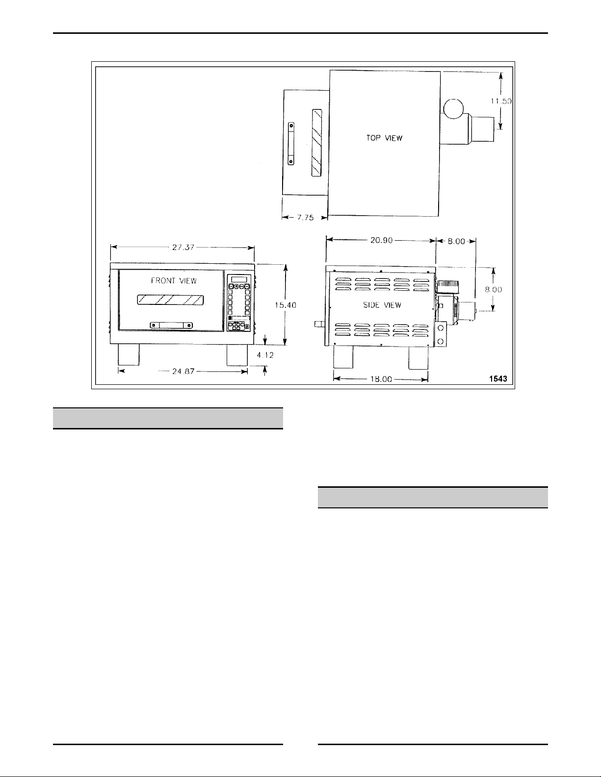
Dimensions
FlashBake OVEN - GENERAL
TOOLS
Standard
• Standard set of hand tools
• VOM with AC current tester (Any VOM with a
sensitivity of at least 20,000 ohms per volt)
Special
• Elect rogrease - 424 031-1 used on relay board
high voltage connections.
• Heat sink compound - 519504 used on high limit
thermostat and thermistor.
• Hi-Tem p Lock-Ti te (green) - 424 028-1 used on
pulley plates.
• Hi-Temp grease - 424023-1 used on pulley driv e
shaft.
• General P urpose Silicone - 424030-1 - used on
gasket.
• Grounding K it - 84919.
• Torque Wrench (in•lb)
LUBRICATION
• Hy-Temp Grease - 424023-1 - Pulley drive
shaft
5
FlashBake OVEN - REMOVAL AND REPLACEMENT OF PARTS
REMOVAL AND REPLACEMENT OF PARTS
COVERS AND PANELS
WARNING:
POWER TO THE MACHINE AT THE MAIN CIRCUIT
BOX. PLACE A TAG ON THE CIRCUIT BOX
INDICATI NG THE CIRCUIT IS BEING SERV ICED.
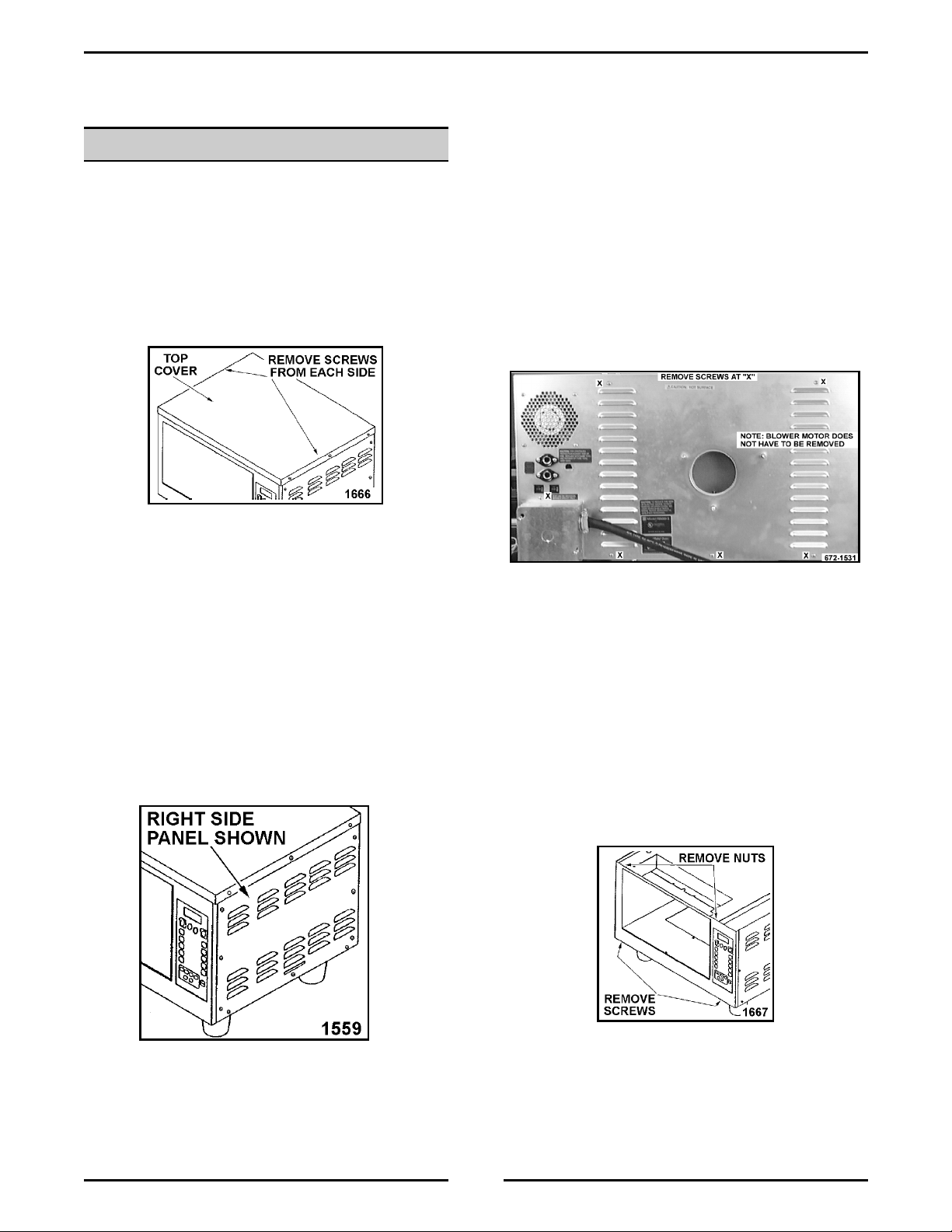
Top Cover
1. Remove the screws from both sides of the cover.
2. Lift strai ght up on the cover and rem ove it f rom
the ov en.
NOTE:
back panel screws.
3. Reverse proc edur e to install .
Right or Left Side Panels
DISCONNECT THE ELECTRICAL
The bac k has a cut-out to al low for the
Back Panel
1. Remove the top cover as outlined under
“COVERS AND PANELS”.
2. Disconnect the lead wires from the fuses, circuit
breakers, control cooling fan and exhaust fan.
3. Remove the screws that secure the back panel to
the ov en.
4. Lift up to clear the junction box on the lower right
corner of the oven on units that are hard wired.
5. Reverse proc edur e to install .
Front Panel
1. Remove the top cover as outlined under
“COVERS AND PANELS”.
1. Remov e the screws from the t op cover on the
side you are wanting to r emov e.
2. Remove the screws that secure the side panel to
the ov en fram e.
NOTE:
openings down.
3. Reverse proc edur e to install .
Position t he side panels with the l ouv er
2. Remove the three screws from the front edge of
the left side panel.
3. Remov e the right side panel as outlined under
“COVERS AND PANELS” and disconnect the
lead wires to the control panel.
4. Remove the screws that secure the front panel to
the bottom of the oven.
5. Remove the nuts from the studs on the top o f the
front panel and remove the front panel.
6. Reverse proc edur e to install .
6

FlashBake OVEN - REMOVAL AND REPLACEMENT OF PARTS
Top Plate Panel
1. Remove the top cover as outlined under
“COVERS AND PANELS”.
2. Disconnect the lead wires to the high limit
thermostat .
3. Remove the thermistor and wire ties attached to
the top plat e.
4. Remove the screws that secure the top plate.
5. Remove the nuts f r om the f r ont studs.
6. Pull top plat e toward back of ov en until the front
edge has cleared the door lock.
NOTE:
have t o rem ove the rack dri v e p u l ley as outli ne
under “RACK DRIVE P ULLE Y ”.
3. Reverse proc edur e to install .
Back Panel
1. Remove the side panels as outlined under
“OVEN CAVITY PANELS”.
2. Remove the screws that secure the panel to t he
oven cavi ty outer wall.
3. Pull the panel to the front of the oven to remove.
4. Reverse proc edur e to install .
Upper Panel
1. Remove the side panels as outlined under
“OVEN CAVITY PANELS”.
2. Remove the screws that secure the panel to t he
oven cavi ty wall.
When removing the right panel, you may
7. Reverse proc edur e to install .
OVEN CAVITY PANELS
WARNING:
POWER TO THE MACHINE AT THE MAIN CIRCUIT
BOX. PLACE A TAG ON THE CIRCUIT BOX
INDICATI NG THE CIRCUIT IS BEING SERV ICED.
CAUTION: Do not scratch or d ull the surface of
the reflective oven cavity panels. This could affect
the operation of the oven.
Side Panels
1. Remove the screws that secure the panel to t he
oven cavi ty outer wall.
2. Pull the panel to the fro n t of the oven to remove.
If the right side panel is difficult to remove, check
the top edge where it m eets the upper panel . It
may be caught on the edge.
DISCONNECT THE ELECTRICAL
3. Pull the panel to the front of the oven to r e move.
4. Reverse proc edur e to install .
7
FlashBake OVEN - REMOVAL AND REPLACEMENT OF PARTS
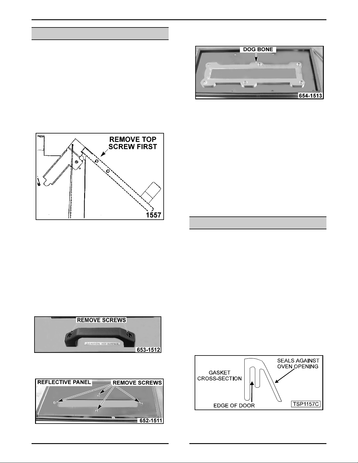
DOOR
WARNING:
POWER TO THE MACHINE AT THE MAIN CIRCUIT
BOX. PLACE A TAG ON THE CIRCUIT BOX
INDICATI NG THE CIRCUIT IS BEING SERV ICED.
Removal
1. Open the door to expose the screws on the side
of the door.
2. Remove the screw that is closest to the top of the
door from each side.
DISCONNECT THE ELECTRICAL
4. Remove the nuts that secure the dog bone to the
outer door panel and r emov e the dog bone.
NOTE:
temp l ock-tite on t he stud threads. Tighte n the
nuts to
will cause the outer door panel to become
deformed.
NOTE:
pattern allows for installation one way. The
reflective glass should be positioned to the
interior of the oven cavity and the welder’s glass
to the customer side. There will be a “W”
stamped in t he dog bone indicating t he welder’s
glass.
When instal li ng the dog bone, use hi gh
8 in•lb
. Do not over tighten the nuts. This
When i nstalli ng the dog bone, the hole
3. Allow the door to move to the open position and
remove the remaining screws.
4. Pull t he door from the hinges.
5. Reverse proc edur e to install .
Disassembly
1. Remove the door as outlined under “DOOR”.
2. Remove the door handle from the door.
3. Remove the inside reflective panel for t he door .
5. Reverse proc edur e to install .
DOOR GASKET
WARNING:
POWER TO THE MACHINE AT THE MAIN CIRCUIT
BOX. PLACE A TAG ON THE CIRCUIT BOX
INDICATI NG THE CIRCUIT IS BEING SERV ICED.
1. Remove the door as outlined under “DOOR”.
2. Disassembly the door to expose the gasket.
3. Remov e t he gasket f r om the i nside edge of the
door.
4. Remove any silicone from the opening.
5. Apply general purpose silicone in t h e groove of
the gasket that is att ached to the edge of the
door.
DISCONNECT THE ELECTRICAL
8
FlashBake OVEN - REMOVAL AND REPLACEMENT OF PARTS
6. Install t he repl acem ent gasket ont o t h e edge of
the opening and allow to set for a minimum of
before cooking.
hours
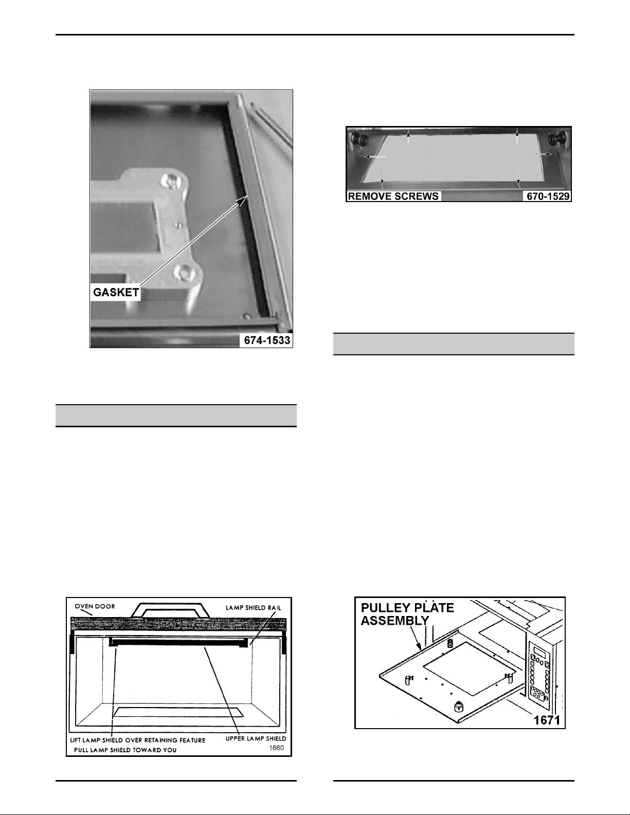
Lower Lamp Shield
8
1. Open the door and remove the rack.
2. Remov e the screws fro m the f ram e of t he lower
lamp shield.
3. Push the shield assembl y to the lef t side of the
oven.
4. Lift the fr ont edge of the frame up.
5. Pull the lower lamp shield from the oven. You may
have t o maneuver it around t he pulleys.
6. Reverse proc edur e to install .
PULLEY PLATE ASSEMBLY
7. Re-assemble the door and install the door on the
oven.
LAMP SHIELDS
WARNING:
POWER TO THE MACHINE AT THE MAIN CIRCUIT
BOX. PLACE A TAG ON THE CIRCUIT BOX
INDICATI NG THE CIRCUIT IS BEING SERV ICED.
Top Lamp Shield
1. Open the door.
2. Lift the front edge of the shield over the retaining
feature.
3. Pull the shield toward you and remove it from the
oven.
DISCONNECT THE ELECTRICAL
WARNING:
POWER TO THE M A CHINE AT THE MA IN CIRCUIT
BOX. PLACE A TAG ON THE CIRCUIT BOX
INDICATI NG THE CIRCUIT IS BEING SERV ICED.
NOTE:
right front corner with the screw faci ng the front.
NOTE:
is shorter than the two roller supports on the left side.
Removal
1. Remov e t he lower l am p shiel d as outl ined under
“LAMP SHIELDS”.
2. Remove the screw from the front edge of the
roller plate.
3. Pull t he roller plate out of the oven cavi ty.
DISCONNECT THE ELECTRICAL
The horizontal roller support is positioned in the
The vertical roller support in the left rear corner
4. Reverse proc edur e to install .
9
 Loading...