

Page 1
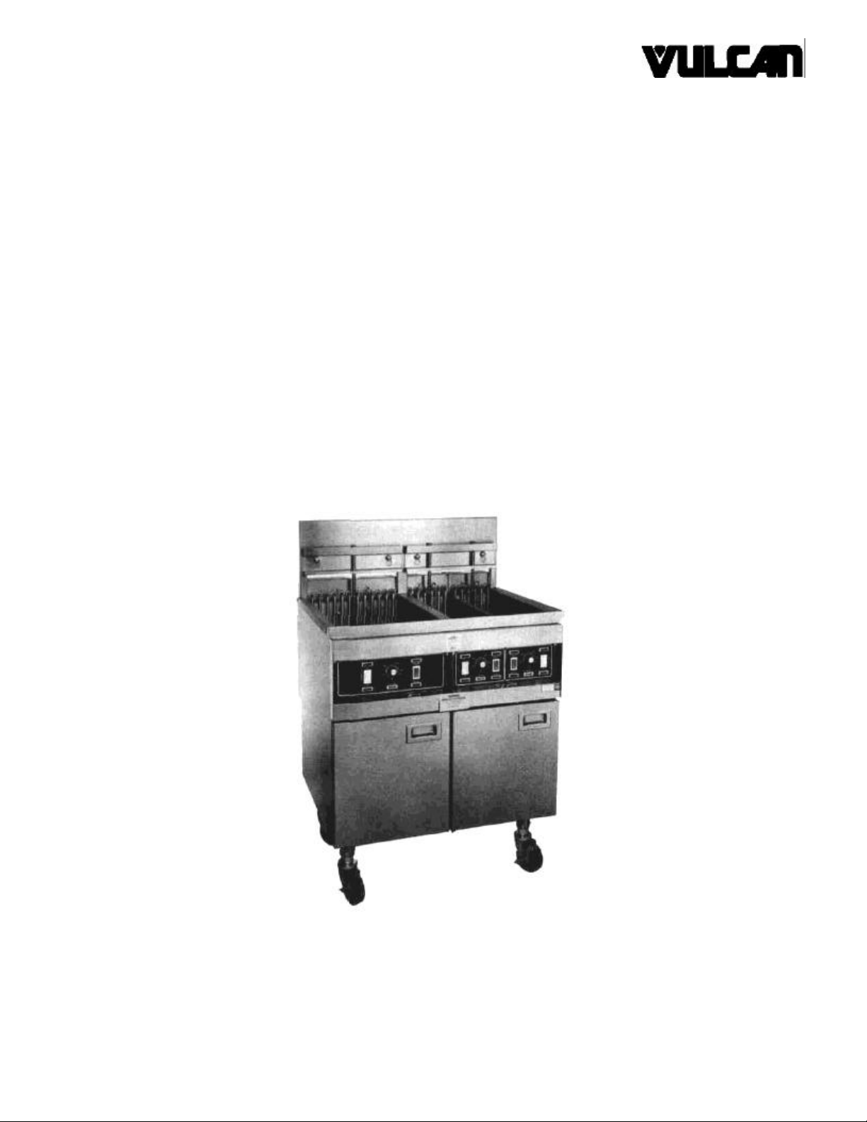
MCDONALD'S ELECTRIC FRYERS
INSTALLATION, SERVICE
AND PARTS
MANUAL FOR MODELS
REF-1M and REF-2SM
VULCAN-HART COMPANY, P.O. BOX 696, LOUISVILLE, KY 40201-0696, TEL. (502) 778-2791
Page 2
OPERATING, INSTALLATION AND SERVICE PERSONNEL
Operating information for this equipment has been prepared for use by qualified and/or authorized operating
personnel.
All installation and service on this equipment is to be performed by qualified, certified, licensed and/or
authorized installation or service personnel, with the exception of any marked with a c in front of the part
number.
Service may be obtained by contacting the Factory Service Department, Factory Representative or Local
Service Agency.
DEFINITIONS
QUALIFIED AND/OR AUTHORIZED OPERATING PERSONNEL
Qualified or authorized operating personnel are those who have carefully read the information in this manual
and are familiar with the equipment's functions or have had previous experience with the operation of the
equipment covered in this manual.
QUALIFIED INSTALLATION PERSONNEL
Qualified installation personnel are individuals, a firm, corporation or company which either in person or
through a representative are engaged in, and are responsible for:
1. The installation of gas piping from the outlet side of the gas meter, or the service regulator when the meter
is not provided, and the connection and installation of the gas appliance. Qualified installation personnel
must be experienced in such work, be familiar with all precautions required, and have complied with all
requirements of state or local authorities having jurisdiction. Reference in the United States of America National Fuel Gas code ANSI Z223.1 (Latest Edition). In Canada-Canadian Standard CAN1-B149.1 NAT.
GAS (Latest Edition) or CAN1-B149.2 PROPANE (Latest Edition).
2. The installation of electrical wiring from the electric meter, main control box or service outlet to the electric
appliance. Qualified installation personnel must be experienced in such work, be familiar with all
precautions required, and have complied with all requirements of state or local authorities having
jurisdiction. Reference: In the United States of America-National Electrical Code ANSI NFPA No. 70
(Latest Edition). In Canada-Canadian Electrical Code Part 1 CSA -C22.1 (Latest Edition).
QUALIFIED SERVICE PERSONNEL
Qualified service personnel are those who are familiar with Vulcan equipment who have been endorsed by
the Vulcan-Hart Corporation. All authorized service personnel are required to be equipped with a complete set
of service parts manuals and stock a minimum amount of parts for Vulcan equipment.
SHIPPING DAMAGE CLAIM PROCEDURE
For your protection, please note that equipment in this shipment was carefully inspected and packed by
skilled personnel before leaving the factory. The transportation company assumes full responsibility for safe
delivery upon acceptance of this shipment.
If shipment arrives damaged:
1. VISIBLE LOSS OR DAMAGE — Be certain this is noted on freight bill or express receipt and signed by
person making delivery.
2. FILE CLAIM FOR DAMAGES IMMEDIATELY — Regardless of extent of damage.
3. CONCEALED LOSS OR DAMAGE — If damage is unnoticed until merchandise is unpacked, notify
transportation company or carrier immediately, and file "concealed damage" claim with them. This should
be done within (15) days of date of delivery is made to you. Be sure to retain container for inspection.
We cannot assume responsibility for damage or loss incurred in transit. We will, however, be glad to furnish
you with necessary documents to support your claim.
PLEASE RETAIN THIS MANUAL FOR FUTURE REFERENCE
Page 3

IMPORTANT NOTES FOR ALL VULCAN APPLIANCES
1. These units are produced with the best possible workmanship and material. Proper installation is vital if best performance and
appearance are to be achieved. Installer must follow the installation instructions carefully.
2. Information on the construction and installation of ventilating hoods may be obtained from the "Standard for the installation of
equipment for the removal of smoke and grease laden vapors from commercial cooking equipment," NFPA No. 96 (latest
edition) available from the National Fire Protection Association, Battery March Park, Quincy MA 02269.
3. For an appliance equipped with a flexible electric supply cord, the cord is equipped with a three prong (grounding) plug. This
grounding plug is for your protection against shock hazard and should be plugged directly into a properly grounded three prong
recepticle. Do not cut or remove the grounding prong from this plug. If the appliance is not equipped with a grounding plug, and
electric supply is needed, ground the appliance by using the ground lug provided (refer to the wiring diagram).
(FOR GAS APPLIANCES ONLY)
4. Do not obstruct the air flow into and around the appliance. This air flow is necessary for proper combustion of gases and for
ventilation of the appliance. Provisions for ventilation of incoming air supply for the equipment in the room must be in accordance
with National Fuel Gas Code ANSI Z223.1 (latest edition).
5. Do not obstruct the flow of flue gases from the flue duct (when so equipped) located on the rear (or sides) of the appliance. It is
recommended that the flue gases be ventilated to the outside of the building through a ventilation system installed by qualified
personnel.
6. For an appliance equipped with casters, (1) the installation shall be made with a connector that complies with the Standard for
Connectors for Movable Gas Appliances, ANSI Z21.69 (latest edition), and Addenda, Z21.69a (latest edition), and a quickdisconnect device that complies with the Standard for Quick-Disconnect Devices for Use With Gas Fuel, ANSI Z21.41 (latest
edition), and Addenda, Z21.41 a (latest edition) and Z21.41 b (latest edition), and (2) adequate means must be provided to limit
the movement of the appliance without depending on the connector and the quick-disconnect device or its associated piping to
limit the appliance movement. If disconnection of the restraint is necessary, reconnect this restraint after the appliance has been
returned to its originally installed position.
7. The appliance and its individual shutoff valve must be disconnected from the gas supply piping system during any pressure
testing of that system at test pressures in excess of 1/ 2 psig (3.45 k Pa).
8. The appliance must be isolated from the gas supply system by closing its individual manual shutoff valve during any pressure
testing of the gas supply system at test pressures equal to or less than 1/ 2 psig (3.45 k Pa).
CAUTIONS
FOR YOUR SAFETY
DO NOT STORE OR USE GASOLINE OR OTHER FLAMMABLE VAPORS AND LIQUIDS
IN THE VICINITY OF THIS EQUIPMENT OR ANY OTHER APPLIANCE.
1. KEEP THE APPLIANCE FREE AND CLEAR FROM ALL COMBUSTIBLE SUBSTANCES.
2. IN THE EVENT A GAS ODOR IS DETECTED, SHUT UNIT(S) DOWN AT THE MAIN
SHUTOFF VALVE AND CONTACT THE LOCAL GAS COMPANY OR GAS SUPPLIER
FOR SERVICE.
3. POST IN A PROMINENT LOCATION, INSTRUCTIONS TO BE FOLLOWED IN THE EVENT
THE SMELL OF GAS IS DETECTED. THIS INFORMATION MAY BE OBTAINED FROM A
LOCAL GAS SUPPLIER.
Page 4
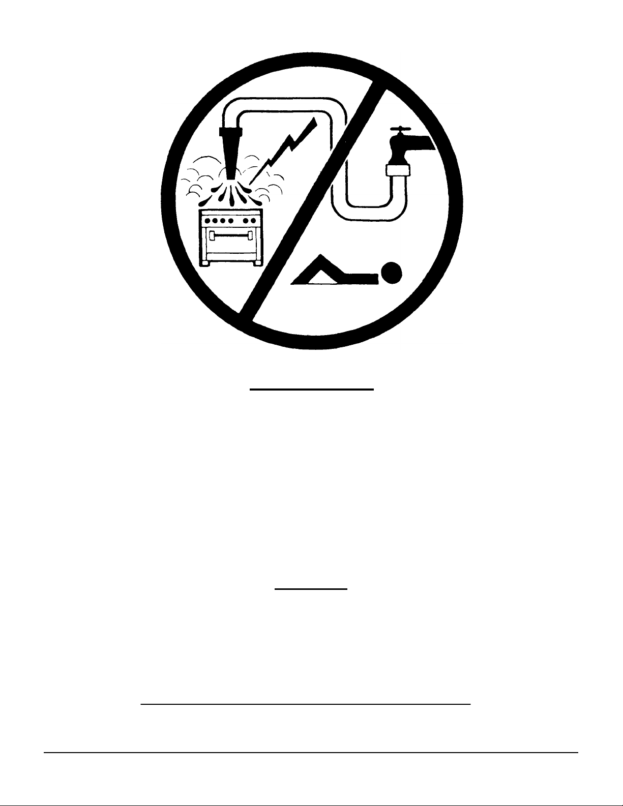
WARNING:
DO NOT SPRAY LIQUIDS OR VAPORS ON OR
NEAR EQUIPMENT UTILIZING ELECTRICITY
CAUTION
FROM THE TERMINATION OF THE APPLIANCE FLUE VENT TO THE FILTERS OF THE HOOD VENTING SYSTEM, AN 18
INCH MINIMUM CLEARANCE MUST BE MAINTAINED.
REFERENCE: ANSI/NFPA 96-1984 4-1.2.2.2. OF THE NATIONAL FIRE PROTECTION ASSOCIATION INC.,
BATTERYMARCH PARK, QUINCY, MASS. 02269, AND NATIONAL BUILDING CODE 1976 SEC. 1015.7b OF THE
AMERICAN INSURANCE ASSOCIATION ENGINEERING AND SAFETY SERVICE, 85 JOHN STREET, NEW YORK, N.Y.
10038.
IMPORTANT
THIS EQUIPMENT IS DESIGN CERTIFIED BY A NATIONALLY
RECOGNIZED TESTING LABORATORY TO THE
APPROPRIATE NATIONAL STANDARDS AS INDICATED ON
THE EQUIPMENT RATING PLATE. ANY MODIFICATION
WITHOUT WRITTEN PERMISSION OF VULCAN-HART
CORPORATION VOIDS THE CERTI FICATION AND WARRANTY
OF THIS UNIT.
115591-4
Page 5
REF FRYER INSTALLATION, SERVICE &
PARTS MANUAL INDEX
Your Vulcan fryer is produced with the best possible workmanship and material. Proper usage and maintenance will
result in many years of satisfactory performance.
DESCRIPTION PAGE
DEFINITION OF PERSONNEL (Inside front cover) 115591-2
CAUTIONS, WARNINGS & IMPORTANT NOTATIONS 115591-2 THRU -5
SECTION 1 - INSTALLATION INSTRUCTIONS 115591-6
SECTION 11 - SERVICE 115591-7 THRU -13
SECTION III - TROUBLE SHOOTING 115591-14 THRU -15
SECTION IV - PARTS LIST & PHOTOS 115591-16 THRU -33
REVISION PAGE (Inside back cover) 115591-34
A RATING PLATE IS LOCATED ON THE INSIDE FRYER DOOR PANEL STATING THE MODEL NUMBER, SERIAL NUMBER,
VOLTAGE AND AMPERAGE. FRYER MUST BE INSTALLED AT LEAST 16 INCHES AWAY FROM OPEN TOP FLAME UNITS.
The manufacturer suggests that you thoroughly read this entire
manual and carefully follow all of the instructions provided.
A complete set of wiring diagrams are packaged separately and placed in the fryer tank for shipment. A wiring decal may also be
found mounted behind the contactor cover door of the unit.
115591-5
Page 6
SECTION I INSTALLATION
DETAIL A
DETAIL B
115591
-
6
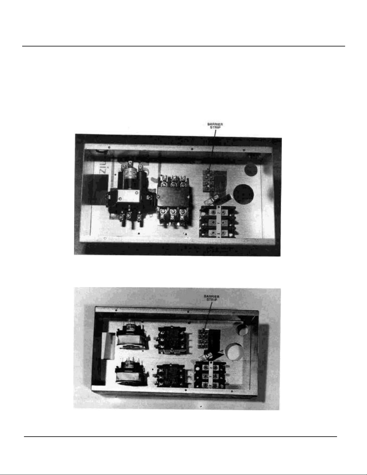
Place fryer as near to its' final position as possible. Connect 120V 60 Hertz electric supply to fryer barrier strip.
Barrier strip may be connected from rear of unit. To reach
barrier, remove electric cover plate from unit. After connecting 120V 60 Hertz electric supply to fryer barrier
strip, verify with a voltmeter that the following condition
exists. (See Details A & B).
1. Black to white 120V 60 Hertz.
2. Black to ground 120V 60 Hertz.
3. White to ground 0.00V 60 Hertz.
For each 15 1/2" section a high voltage line capable of
handling 16 KW at the unit's rated voltage (208, 240,
480) is required. If a fan interlock is needed, it should be
connected to 1 and 2 on the barrier strip. 1 and 2 go to a
set of dry contacts on the power switch.
Page 7
SECTION II SERVICE___________________________________________
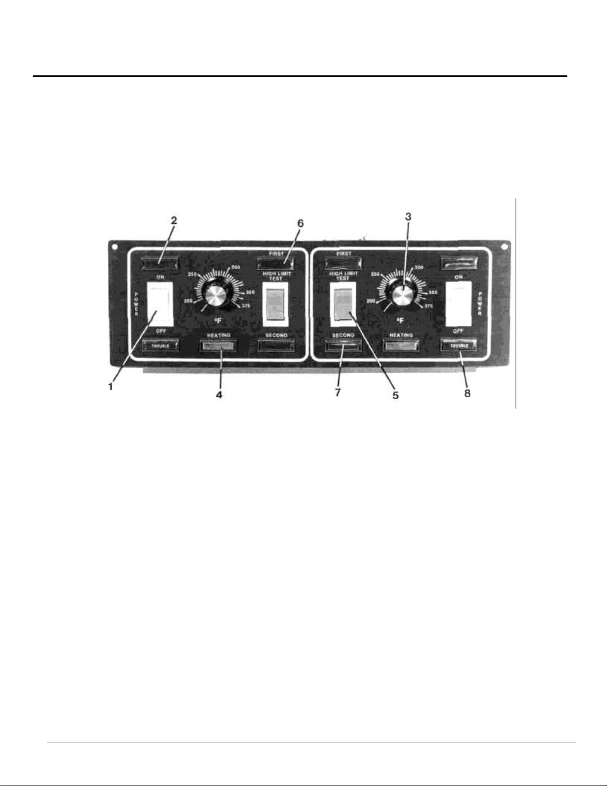
SWITCH PANEL OPERATION
DETAIL A1
1. MASTER SWITCH - Controls electric supply to unit. (Optional - ventilator interlock.)
2. POWER "ON" LIGHT - Light Indicates when electrical supply is on.
3. TEMPERATURE CONTROL - Maintains frying temperature by controlling power supply.
4. HEATING LIGHT
5. HIGH LIMIT TEST SWITCH - Bypasses temperature control for testing of high limit thermostats.
6. FIRST HIGH LIMIT LIGHT - When "On", indicates first high limit thermostat has shut down.
7. SECOND HIGH LIMIT LIGHT
8. TROUBLE LIGHT - Indicates unit has been shut down by second high limit thermostat.
- When "On", indicates temperature control is calling for power to
elements.
- When "On", indicates second high limit thermostat has shut down
unit. (reset required)
115591-7
Page 8
SECTION II SERVICE (Continued)
CLEANING HEATING ELEMENTS & THERMOSTAT BULB
1. The kettle must be at operating temperature.
2. Turn master switch off.
3. Raise elements out of hot shortening with a lift rod and
allow shortening to drip off for five minutes.
CAUTION
4. Place cover(s) over kettle(s). To prevent fire and
preserve clean shortening.
5. Turn operating thermostat to 300°F. (148.8°C).
6. Turn master switch on. Do not leave the fryer
unattended. The second high limit will trip out
terminating the bum off cycle
7. Turn master switch off at termination of burn off cycle.
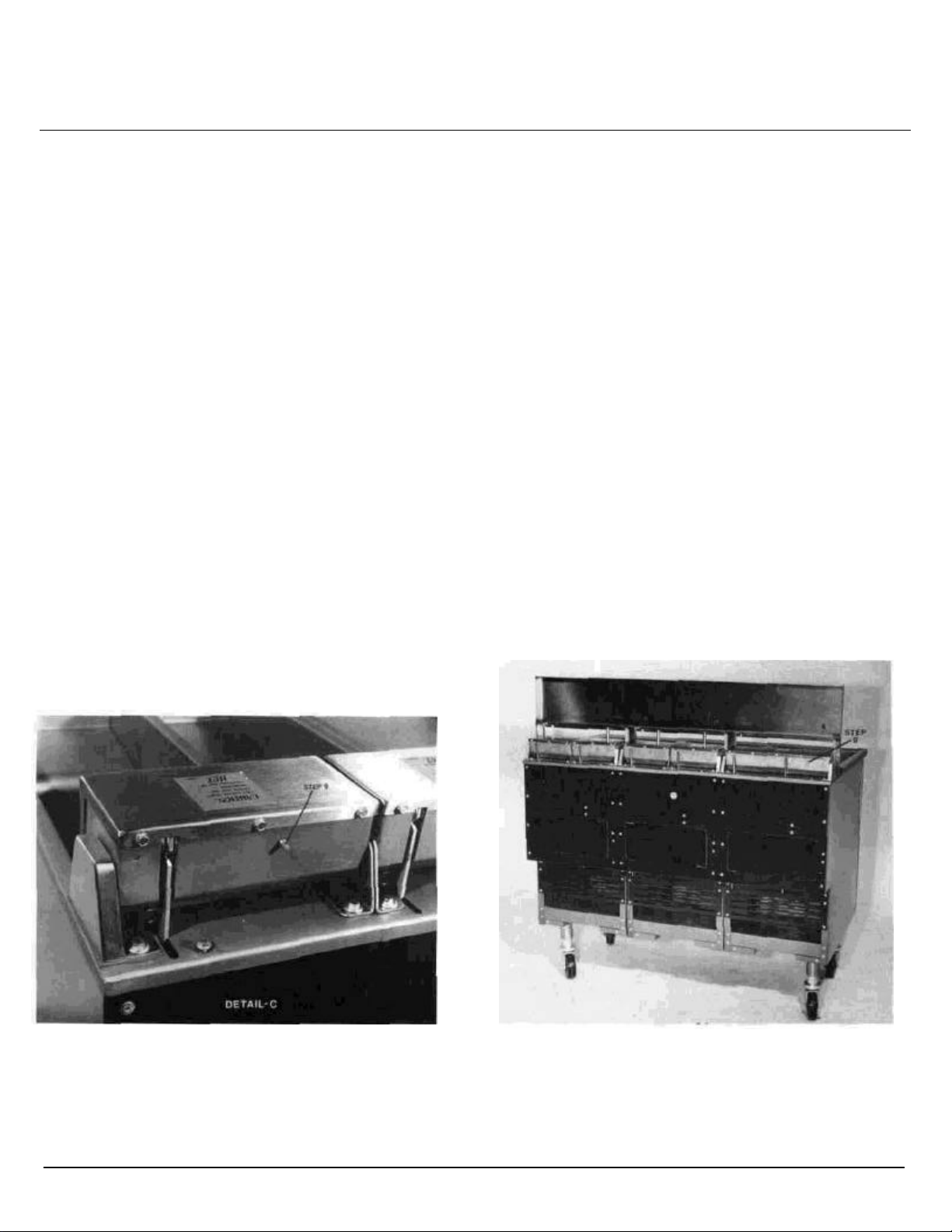
DETAIL C DETAIL C1
15591-8
8. Heating elements will heat up in excess of 600°F
(315.5°C) glowing red. If any do not glow, call service
agency. Some smoking, cracking sound and flames will
occur. This is normal. If excessive flaming occurs,
extinguish immediately to prevent damage to elements
and thermostat bulbs.
9. Allow elements to cool and press reset button on rear
of element head (See Detail C & C1).
10. Brush residue from elements and thermostat bulbs with
a stiff nylon brush. Care should be taken not to bend or
displace temperature controller bulbs.
11. Remove cover(s) from kettle(s) and lower elements into
shortening.
12. Proceed with filtering procedures.
Page 9

SECTION II SERVICE (Continued)
THERMOSTAT CALIBRATION PROCEDURES
1. Thermostat calibration is factory set before unit shipment. Thermostat calibration should not be performed
unless unit temperature is registered within 5°F (15°C) plus or minus the thermostat setting.
Check thermostat calibration as follows:
NOTE: The following tools will be required: Digital pyrome-
ter and holder, 1/8" flatblade, screwdriver, maple
paddle.
1. The shortening must be at the proper level as indicated
by the indicator line on the vat wall.
2. Inset a digital pyrometer, alnor pyrometer or a deep fat
thermometer at the rear of the fryer exactly where the
computer probe would go.
3. Set the thermostat knob at the correct cooking temperature and turn on unit.
4. Allow the shortening temperature to stabilize by letting
the fryer cycle on and off after reaching the desired
temperature at least three times.
5. Agitate the shortening using maple paddle until step
6 is completed
6. After the stabilizing period, the instant the burner acates (as noted by the burners "On" light turning on),
the shortening temperature should be plus of minus
5°F (-15°C) of the thermostat setting.
7. If it is within ± 5°F (-15°C) you are finished
calibrating. If not follow steps 8 thru 11 for
recalibration.
8. Loosen the set screw in the temperature control
knob. Rotate knob without moving shaft and set the
knob to match the pyrometer reading.
9. Retighten the set screw. CAUTION: Do not
overtighten.
10. Turn the dial to the desired temperature.
11. Repeat steps 4,5 and 6.
NOTE: Do not calibrate using new shortening unless
you agitate the shortening as indicated in
step 5.
115591-9
Page 10
SECTION II SERVICE (Continued)
DETAI
L
C2 115591
-
10
SERVICING MULTI-FUNCTION BOARD
NOTE: The multi-function board incorporates the follow
ing features utilizing a thermosistor probe to
sense fat melt cycle, fat melt temperature trip,
oil temperature and the first high limit tempera
ture trip.
A. Melt Cycle & Temperature
1. Set the temperature control knob to the frying
temperature and turn on the master switch.
2. After an initial off period of approximately 45
seconds, the elements will cycle on for 2 seconds
and off for 28 seconds until the shortening melts
and a temperature of 135°F (57°C) is obtained,
after which the operating thermostat will take over
and bring the unit to the set temperature. If the fat
melt cycle responds, but comes out of fat melt at
more than ± 10° of 135° F. (57°C) see fat melt
calibration procedures in item no. 3. If the fat melt
cycle fails to respond, see item 4 below.
3. Fat Melt Calibration
NOTE: This procedure should be performed by an
authorized service person only. If the unit is
coming out of the fat melt cycle at ± 10°F (-12°C),
try the following calibration procedure before
replacing the multi-function board.
A. Insert pyrometer in place of the computer
probe.
B. Turn unit "off" and allow unit to cool to below
135°F (57°C) or begin calibration from cold
start.
C. Remove (2) screws from upper corners
of control panel, drop control panel down, dis-
connect the electric harness and remove panel.
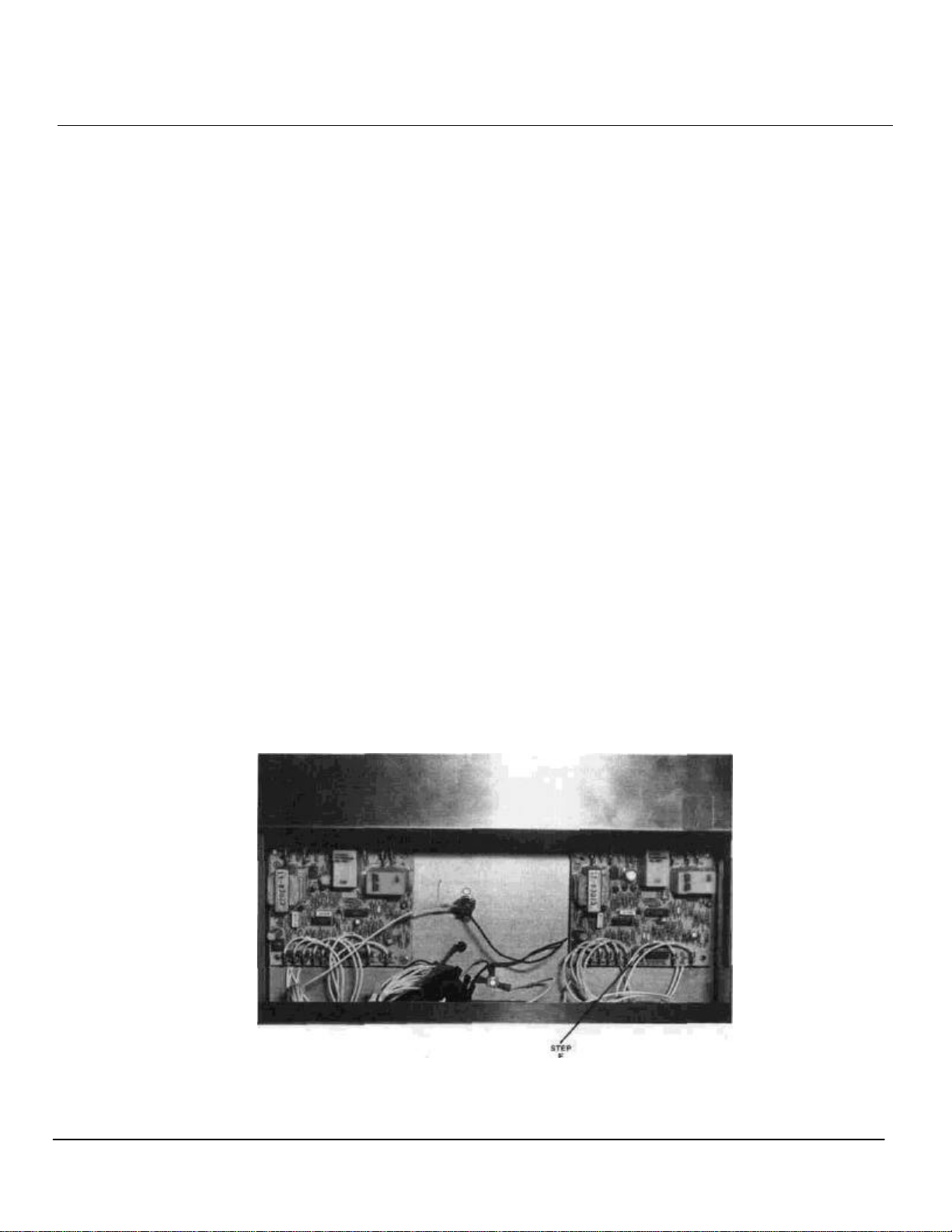
D. Locate defective multi-function board on
back wall of the control area.
E. Locate fat melt adjustment screw resting in the
bottom center of the board to the right of pin #12.
F. Remove the adjustment screw sealant by
gently chipping with screwdriver
G. Turn fat melt adjustment screw full clockwise.
H. Connect a DC voltmeter between pins 13 and 15.
I. Reconnect control panel wire harness while
holding panel assembly in hand. Turn power switch
"On" and set the potentiometer knob to frying
temperature.
J. Check DC voltmeter for a reading of 5 volts
K. When pyrometer reaches 135°F (57°C) and while
observing the voltmeter gently rotate fat melt
adjustment screw counterclockwise until DC
voltmeter reads 0 volts.
NOTE: It is advisable to secure adjustment screw
by placing a small drop of enameled paint or
fingernail polish in center of screw. Calibration is
now complete, remove voltmeter and replace
control panel.
4. If the fat melt cycle is inoperative, the multi-funcion
control board must be replaced.
NOTE: Field repair of the multi-function board is
not practical, therefore, when the board
malfunctions, it must be completely replaced. Ref.
to Detail C2
Page 11

SECTION II SERVICE (Continued)
SERVICING MULTI -FUNCTION BOARD (Continued)
To replace multi-function board, disconnect unit
power and remove (2) screws in the upper comers
of the control panel. Fold down control panel as sembly. Disconnect electrical harness and remove
panel. The multi-function boards are located on
the back wall of the control box area. Ref. to
Detail C.
NOTE: Split vat units utilize (2) boards, (1) to the
right and (1) to the left upper wall. Single vat units
utilize (1) board mounted to the upper left wall.
Remove (4) screws securing defective board. Disconnect multi pinned plug. Remove the 11 wire
connections one at a time transfering each connector from the old board onto the new board.
Reconnect multi pinned plug and remount new
multi-function board. Reconnect wire harness and
close up control panel assembly. Reinstall (2)
screws to secure panel mounting.
SERVICE NOTE:
Harness connectors, in split vat fryers, which
serve the same purpose for left side or right sides,
have been identified by a "red" dot for "left" and a
"green" dot for "right". When reconnecting
harness insure that red dots connect to left hand
components and green dots to right hand
components.
6. Stop agitating and allow fryer to cycle On and Off
automatically three (3) times.
7. After the stabilizing period, the instant the element
actuates (as noted by the fryer "On" light turning
on), the shortening temperature should be plus
or minus 5°F. (-15°C) of the thermostat setting.
8. If it is within ± 5°F. (-15°C) you are finished
calibrating.
9. If not, loosen the set screw in the temperature
control knob. Rotate knob without moving shaft
and set the knob, to match the pyrometer
reading.
10. Retighten the set screw.
DO NOT OVERTIGHTEN.
11. Turn the dial to the desired temperature.
12. Repeat steps 6,7 and 8
13. If, after repeating steps 6 thru 7 oil temperature
calibration is not achieved, replacement of the
multi-function board will be required.
B. OIL TEMPERATURE
The fryer oil temperature is controlled by the multi
function board, monitored by the thermistor probe and
set by the potentiometer.
The following calibration check will help determine the
operational status of the temperature controller in the
multi function board.
NOTE: Best results can be obtained by not using new
shortening.
1. The shortening must be at the proper level as indicated by the indicator line on the vat wall.
2. Insert pyrometer, at the rear of the fryer exactly
where the computer probe would go.
3. Set the thermostat knob to the correct cooking
temperature and turn on unit.
4. Allow the shortening temperature to cycle off
after reaching the desired temperature.
5. Agitate the shortening using a maple paddle to
eliminate the cold zone in the bottom of the kettle.
115591-11
14. Replacement of the multi-function board is to be
performed only by a certified Vulcan service
agency. Service personnel should disconnect
unit power and follow board replacement
procedure outlined in item 3 of melt cycle and
temperature in Section II Service.
HIGH LIMIT CONTROL
The function of the high limit control is to shut the unit
down in the event of a thermostat failure which would
allow the cooking oil to be overheated. The operating
temperature of the high limit control is 35° or 60° higher
than the highest temperature allowed by the thermostat
when the thermostat is functioning properly.
In the event of a high limit 'Shut -Down" the entire control
system will be put out of operation.
DO NOT attempt to restart the fryer until the temperature
of the cooking oil has lowered to approximately 350°.
CAUTION
IF THIS SITUATION CONTINUALLY OCCURS, DO
NOTATTEMPT TO BYPASS THE HIGH LIMIT. SHUT
UNIT DOWN AND CONTACT A SERVICE AGENCY.
Page 12

SECTION II SERVICE (Continued)
HIGH LIMIT TEST PROCEDURE
This test is to be made in order to determine if the protec tion devices are properly functioning. (See steps 1 thru
9). Tools required to complete this procedure are: A
pyrometer, maple paddle.
1. Check fryer oil level. Unit oil level must reach vat full
line.
2. Remove computer probe from probe holder.
3. Insert properly calibrated shortening pyrometer probe
into holder.
4. Turn fryer power switch "On", set temperature control
knob at 375°F (190.6°C) and let oil stabilize for at
least 15 minutes.
5. Push and hold top half of red test switch while continuously stirring oil.
6. Record temperature at which first high limit indicator
light turns "On". Indicator should turn "On" between
400° to 420°F (204.4° to 215.6°C). When light
appears, release switch.
NOTE: If first high limit test is failed, contact service
agency. Fryer operation may continue if second high
limit test is passed.
7. To check second high limit, push and hold bottom half
of red test switch, while continuously stirring the the oil
8. Record temperature at which second high limit
indicator light turns "On" indicator should turn on
between 420° to 450°F (215.6° to 232.2°C) when light
appears, release switch.
NOTE: If second high limit test is failed, shut fryer
down immediately and contact service agency.
9. Once unit cools down, reset by turning main power
switch off and then on, normal frying operation will
then automatically be resumed.
The following procedure is to be performed by authorized
service personnel only!
If the high limit test is consistently failed within a range of
±25°F (-3.8°C) high limit calibration of the multi-function
board may correct the problem.
To calibrate the first high limit control of the multi-function
board, complete the procedures below.
1. After failing high limit test, allow fryer to cool until the
high limit light closes, this is marked by the
deillumination of the first high limit light.
2. Remove (2) screws in upper corner of the control
panel, drop control assembly down and hold it in
palm of your hand.
3. Locate the high limit adjustment screw resting next to
wire pin #8 on the lower left hand side of the multifunction board.
4. Using a screwdriver gently chip of the protective
adjustment screw board.
5. Rotate the high limit adjustment screw full clockwise.
6. Depress first high limit test switch using the
pyrometer monitor temperature rise.
7. As the oil temperature approaches 410°F (210°C) be
prepared to rotate adjustment screw counterclockwise. When the oil temperature reaches
410°F (210°C). Gently rotate adjustment screw counterclockwise until the first high limit light illuminates.
Calibration is now complete.
8. Reassemble fryer for normal cooking operation.
DETAIL D DETAIL E
115591-12
Page 13

SECTION II SERVICE (Continued)
DETAIL F
115591
-
13
Replacement Of Mini Fan
The mini fan is located behind the control panel mounted
to the center bottom flange of the control area. The mini
fan is utilized to draw hot air outside of the control area.
Should this fan malfunction, it must be immediately replaced as follows:
1. Disconnect unit power or turn breakers off at main
power source.
2. Remover (1) screw from each of the upper control
panel corners.
3. Drop control panel down and disconnect electrical
harness plug to remove panel assembly from the
control area.
4. Locate mini fan centered in bottom control area
flange.
5. Remove the (4) screws securing fan.
6. Disconnect the (2) fan wires and remove bad fan from
the control area.
7. Install new fan, close up control area. Return unit
power.
Page 14

SECTION III TROUBLESHOOTING GUIDE__________________________
5V power
scheduled maintenance section of equipment
scheduled maintenance section of equipment
A. Set temperature control to normal cooking
equipment
scheduled maintenance section of equipment
WARNING: Inspection, testing and repair of electrical equipment should be performed only by qualified service
personnel. The unit should be unplugged when servicing, except when electrical tests are required.
DANGER: Use extreme care during electrical circuit tests. Live circuits may be exposed.
PROBLEM CAUSE CORRECTIVE ACTION
A. On-Off switch not "On". A. Turn On/Off switch "On" FRYER DOES NOT HEAT.
B. 115V store circuit breaker "Off". B Reset store circuit breaker.
C. Control voltage plug not plugged in wall. C. Plug in all power supply cords & insure
twist locks are engaged.
D. Control circuit not connected to power
inside fryer.
E. On-Off switch defective. E. Replace switch. (Refer to non-scheduled
D. Remove rear panel& check for 11
connection.
maintenance section of equipment manual.)
POWER SWITCH "ON".
POWER LIGHT ON.
OFF.
"ON", NO HEAT LIGHT CONTACTOR
CAN BE HEARD CYCLING EVERY 30
SECONDS.
POWER SWITCH "ON,
POWER LIGHT -ON", NO HEATING LIGHT.
POWER SWITCH "ON", POWER LIGHT
"ON", AND NO HEATING LIGHT,
TROUBLE LIGHT & SECOND LIMIT "ON".
A. Ventilator circuit breaker tripped. A. Reset vent circuit breaker.
B. Open wiring in interlock system. B. Call service agency.
C. Defective power switch. C. Replace power switch. (Refer to non-
manual.)
A. High voltage store circuit breaker
tripped, (one for each 15 1/2" fryer section.)
B. Heating light defective. (Oil temperature
increasing without heating light.)
A. Temperature control set too low
B. Fat melt timer is inoperative.
C. Multi-function temperature control
board is inoperative.
A. Shortening temperature above 435°F
(224°C) second high limit inoperative.
B. Second high limit inoperative (will not
reset).
A. Reset vent circuit breaker POWER SWITCH "ON", POWER LIGHT
B. Replace heating light. (Refer to nonmanual.)
temperature.
B. & C. Replace multi-function temperature
& board. (Refer to non-
scheduled maintenance section of
manual.
A. Allow shortening to cool to 390° (199°C)
and push second high limit reset button.
B. Replace second high limit. (Refer to non manual.)
115591-14
Page 15

SECTION III TROUBLESHOOTING GUIDE
B. Solid fat not properly located on heating
&
scheduled maintenance section of equipment
element.
connection.
scheduled maintenance section of equipment
PROBLEM CAUSE CORRECTIVE ACTION
MELT CYCLE DOES NOT FUNCTION
(UNIT GOES TO FULL HEAT WHEN
TURNED "On").
A. Thermistor sensor is still hot from a
previous change of hot shortening.
A. Allow kettle to cool. To force cool, pack solid
shortening around probe (between elements at
rear).
UNIT GOES TO FULL POWER BEFORE
SHORTENING AROUND ELEMENTS IS
DISSOLVED.
SHORTENING WILL NOT MELT
WITHIN 45 MINUTES.
B. Melt function defective. B. Replace multi-function temperature control
board. (Refer to non-scheduled maintenance
section of equipment manual.
A. Wire rack not removed prior to adding
solid shortening.
element.
C. Fat melt function defective. C. Replace multi-function temperature control
A. Melt cycle thermostat out of calibration. A. Adjust fat melt thermostat function. (Refer to
B. Melt cycle timer incorrect. Should be 2
seconds "On", 28 seconds "Off".
C. Defective heating element. C. Call service agency to replace heating
D. Heating element power/supply problem. D. Check breakers X -Y-Z block for bad
A. Remove rack, allow system to cook & initiate
fat melt.
B. Be sure block is centered over element coils
push full to back of fryer.
board. (Refer to non-scheduled maintenance
section of equipment manual.)
nonmanual.)
B. Replace multi-function temperature control
board. (Refer to non-scheduled maintenance
section of equipment manual.)
UNIT WILL NOT COME OUT OF FAT
MELT.
FRYER COMES "ON", NO FAT MELT
CYCLE. FRYER HEATS UNTIL SECOND
HIGH LIMIT TRIPS. (RUN-AWAY)
FRYER GOES THROUGH FAT MELT,
THE FULL HEAT RUNS UNIT
1st OR 2nd HIGH LIMIT TRIPS.
(RUN-AWAY)
LIMIT TEMPERATURE BELOW
375°F. (190. 5)°C).
115591-15
A. Defective multi-function temperature
control board.
A. Stuck mercury relay in temperature
control system.
A. Defective temperature control board. A. Replace temperature control board. (Refer to
A. Fryer out of calibration. A. Recalibrate, see calibration FRYER SHUTS DOWN WITH HIGH
B. Improper first high limit calibration. B. Calibration of first high limit required. Contact
A. Replace multi-function temperature control
board. (Refer to non-scheduled maintenance
section of this manual.)
A. Turn unit "Off" and tag fryer for non-use until
service agency has repaired.
non-
manual.)
service agency.
Page 16

SECTION IV PARTS LIST________________________________________
REF FRYER
REPLACEMENT PARTS LIST
&
PHOTOS
REPLACEMENT PARTS ORDERING
THE FOLLOWING INFORMATION MUST ACCOMPANY A REPLACEMENT PARTS ORDER OR IT CANNOT BE FILLED.
A. MODEL AND STYLE OR SERIAL NUMBER
B. VOLTAGE AND PHASE.
C. APPLIANCE FINISH, PERMAFINISH, STAINLESS STEEL ETC. (IF APPLICABLE TO PART TO BE REPLACED.)
THIS INF ORMATION CAN BE FOUND ON THE RATING PLATE LOCATED INSIDE THE FRYER DOOR PANEL.
PARTS MAY BE ORDERED FROM YOUR DEALER, SERVICE AGENCY, PARTS DISTRIBUTOR.
FOR FURTHER INFORMATION CONCERNING PARTS, ORDERING LOCATION, CONTACT V ULCAN-HART CORPORATION, 3600
NORTH POINT BLVD., BALTIMORE, MD. 21222 OR IN CANADA, VULCAN-HART CANADA INC., 79 WEST STREET, SOUTH,
ORILLIA, ONTARIO, L3V K5.
USE RATING PLATE AND WARNING PLATES LOCATED INSIDE LEFT HAND DOOR PANEL TO HELP YOU OBTAIN THE
INFORMATION LISTED ABOVE. THESE PLATES WILL PROVIDE ALL NECESSARY INFORMATION REQUIRED BY THE SERVICE
AGENCY.
WARNING ALL SERVICE PERSONNEL
WHEN SERVICING THIS EQUIPMENT, USE ONLY CERTIFIED
CONTROLS, DUPLICATING THOSE ORIGINALLY SUPPLIED ON THIS EQUIPMENT BY
VULCAN-HART CORP., DO NOT SUBSTITUTE COMPONENTS WITH DIFFERENT MODEL NUMBERS
DO NOT SUBSTITUTE COMPONENTS WITH DIFFERENT MANUFACTURING NAMES
DO NOT SUBSTITUTE COMPONENTS WITH REBUILT CONTROLS WITHOUT
AUTHORIZATION FROM VULCAN-HART CORP. ANY UNAUTHORIZED SUBSTITUTION OF
CONTROLS AS STATED ABOVE MAY BE A SAFETY HAZARD AND WILL AUTOMATICALLY VOID
THIS WARRANTY AND THE CERTIFICATION ASSOCIATED WITH THIS EQUIPMENT
DETAIL G
115591-16
Page 17

PARTS LIST (Continued)
4SF
*1 114339
-
G1 Main top assembly
1 1
Protects unit from shortening
1
1 1
1
1
5 114159
-
1 Probe tube
1 2 3 2 4 6 3 5 2 4
Holds temperature probe in
place during unit operation.
ITEM PART
No. No. DESCRIPTION 1M 2M 3M 2SM 4SM 6SM 12SM 14SM 2FM
REF REF REF REF REF REF REF REF REF REF
PARTS IDENTIFICATION/FUNCTION/PHOTOS
QUANTITY
FUNCTION
2 114184-G1 Main top assembly
•3 114192-G1 Main top assembly
4 114206-1 Basket hanger 1 2 3 1 2 3 2 3 2 2 Holds probe tubes and fryer
6 114194-8 (Single) control 1 2 3
7 114043-9 (Split) control panel
8 114123-G1
9 111686-2 Hanger button 2 4 6 2 4 6 4 6 4 4 Allow basket hanger to rest on
10 114210-1 Caster with brakes 2 2 2 2 2 2 2 2 2 2
(single unit)
(double unit)
(triple unit)
panel Mylar
Mylar
Door panel
assembly
1 1 1 Protects unit from shortening
1 1 2
1 2 3 1 2
1 2 3 1 2 3 2 3 3 3
10A 114210-2 Caster without
brakes
•11 114244-1
Blank control panel
Mylar
1 1
drippings and supports basket
hanger.
Protects unit from shortening
drippings and supports basket
hanger.
drippings and supports basket
hanger.
baskets.
Protects metal control panel and
describes operators controls.
2 Protects metal control panel and
describes operators controls.
Closes off fryer front and
protects control area.
m ain top.
Adjustable wheel assembly
which allows unit to be rolled in
and out from under hood for
cleaning or relocation.
Used to cover operators control
area on frymate units.
12 114211 Door pull 1 2 3 1 2 3 2 3 3 3 Allows door assembly to be
13 114224-G2 Tank assembly 1 2 3
*Items not shown by photograph
115591-17
(single)
1 1 2
Photo shown on next page.
opened and closed.
Holds shortening and product
while unit is frying.
Page 18

PARTS LIST (Continued)
115591
-18
Page 19

PARTS LIST (Continued)
No.
1
1
1 1 1
1
1 1
Encloses fryer back and protects
Encloses fryer back and protects
ITEM
PART No.
14 114088-G2 Tank assembly
DESCRIPTION
(split)
REF
1M
PARTS IDENTIFICATION/FUNCTION/PHOTOS
QUANTITY
REF
REF
REF
REF
REF
2M
3M
2SM
4SM
1 2 3 1 2
6SM
REF
12SM
REF
14SM
REF
2FM
REF
4SFM
2 Holds shortening and product
while unit is frying.
FUNCTION
l15 114225-1 Fryer back 1
l16 114163-1 Fryer back
17 114199-1 Fryer back
18 114345-1 Rear door 1 2 3 1 2 3 2 3 2 2
19 114146-2 Reset button (high
limit)
20 114344-1 Rear closure 1 2 3 1 2 3 2 3 2 2 Encloses lower portion of fryer
lItems not shown by photograph
1 2 3 2 4 6 3 5 2 4 Used to reset second high limit.
controls from dust etc.
1
the fat melt and high limit
thermostat.
back
115591-19
Page 20

PARTS LIST (Continued)
No.
Control panel cover
ITEM
PART No.
6 114194-8
DESCRIPTION
Mylar control panel
(single)
REF
REF
1M
2M
1 2 3
PARTS IDENTIFICATION/FUNCTION/PHOTOS
QUANTITY
REF
REF
REF
REF
REF
3M
2SM
4SM
6SM
12SM
REF
14SM
1 1 2
REF
2FM
REF
FUNCTION
4SFM
Protects metal control panel and
describes operators control.
7 114043-9
21 115563-1
21A 115563-G1 Wire harness (split)
22 115431-G1
23 114042-G1
23A 114042-G2 Control panel (split)
Mylar Control panel
(split)
Wire Harness
electric (single)
assembly
Control panel
(single)
1 2 3 1 2
1 2 3
1 1 2
1 2 3 1 1 2
1 2 3 1 2 3 2 3 2
1 2 3
1 1 2
1 2 3 1 2
24 111496-E4 Signal light (Red) 3 6 9 6 12 18
25 111496-B1 "On-Off" switch 1 2 3 2 4 6 3 5 2
26 111496-E6 Trouble light 1 2 3 2 4 6 3 5 2
27 111496-E3
28 114254-1
28A 115638-G1 Potentiometer
29 111496-B3 Test switch (red) 1 2 3 2 4 6 3 5 2
Heating light
(amber)
Potentiometer knob
assembly
1 2 3 2 4 6 3 5 2
1 2 3 2 4 6 3 5 2
1 2 3 2 4 6 3 5 2
9 15 6 12 1 st or 2nd high limit light, when
2 Protects metal control panel and
describes operators controls.
Wiring assembly that feeds
supply to fryer control circuit
2
2 Protects the connecting points
of the control panel
1 Supports operators controls,
switches, etc.
2
"On": Indicates that 1 st or 2nd
high limit thermostat has shut
down unit. Power light on
indicates electric supply is "On".
4 Controls electric supply to unit
4 Indicates solid state ignition
device has "locked out".
4 When on indicates temperature
control is calling for gas to
4 Sets shortening temperature
4 Sets shortening temperature
4 Bypasses temperature control
for testing of high limit
thermostats.
115591-20
Page 21

PARTS LIST (Continued)
ITEM
maintop.
olds temperature probe in place
racks (single)
tank
bottom
in proper place.
33 114176
-1
Element clamp
2 4 6 2 4 4
PART No. DESCRIPTION
No.
13 114224-G2 Frytank assembly
(single)
REF
REF
1M
2M
1 2 3
PARTS IDENTIFICATION/FUNCTION/PHOTOS
QUANTITY
REF
REF
REF
REF
REF
REF
REF
REF
3M
2SM
4SM
6SM
12SM
14SM
2FM
4SFM
1 1 2
FUNCTION
Holds shortening and product
while unit is operating.
14 114088-G2 Frytank assembly
(split)
9 111686-2 Hanger buttons 2 4 6 2 4 6 4 6 4 4 Allows basket hanger to rest on
5 114159-1 Probe tube 1 2 3 2 4 6 3 5 2 4 H
4 114206-1 Basket hanger 1 2 3 1 2 3 2 3 2 2 Holds probe tubes and fryer
30 114309-G1 Element head
assembly (single)
30A 114306-G1 Element head
assembly (split)
31 114214-2 Basket support
31A 114214-1 Basket support
racks (split)
32 114177-1 Element clamp
32A 114177-2 Element clamp top 4 8 12 4 8 12 8 12 8 8
34 114137-1 Double element
clamp angle.
35 111830-1 High limit bulb
clamp
1 2 3 1 2
1 2 3
1 2 3
2 4 6 2 4 6 4 10 4 4 Secures and positions elements
1 2 3
4 8 12 8 16 24 12 16 8 16 Secures and positions high limit
1 1 2 Supports fryer elements while
2 4 6 2 4
1 1 2 Supports fryer baskets while in
2 4 6 2 4
1 1 2
2
during unit operation
baskets in place.
allowing elements to be raised
and lowered inside the tank.
4
4
bulb to element assembly.
115591-21
Page 22

PARTS LIST (Continued)
2M
Secures and positions probe
degree of shortening heat for
ITEM
PART No. DESCRIPTION
No.
36 106666-42 Probe clamp 4 8 12 8 16 24 12 24 8 16
37 114142-1 Thermistor probe 1 2 3 2 4 6 3 6 2 4 A device which senses the
38 114027-1 Heating element
38A 114027-2 Heating element
38B 114027-3 Heating element
39 111830-2 Tube clamp-
*42 114146-2 Second high limit 1 2 3 2 4 6 3 5 2 4 A device which protects the
* = NOT SHOWN BY PHOTO
208V
240V
480V
capillary.
PARTS IDENTIFICATION/FUNCTION/PHOTOS
QUANTITY
REF
REF
REF
REF
REF
1M
6 12 18 6 12 18 12 18 12 12 Device which heats
4 8 12 4 8 12 8 12 8 8 Secures high limit capillary
3M
2SM
4SM
REF
6SM
REF
12SM
REF
14SM
REF
2FM
FUNCTION
REF
4SFM
to fryer element assembly.
the temperature control
shortening.
into
fryer in case the first high
limit should fail or the
solenoid becomes stuck in
the open position.
115591-22
Page 23

PARTS LIST (Continued)
115591-23
Page 24

PARTS LIST (Continued)
115591-24
Page 25

PARTS LIST (Continued)
5 114159
-1
Probe tube
1 2 3 2 4 6 2 5 2 4
Holds temperature probe
in place during unit operation.
*11
114244
-1
Blank mylar
1 1 Used to cover operators
QUANTITY
ITEM PART
No. No. DESCRIPTION 1M 2M 3M 2SM 4SM 6SM 12SM 14SM 2FM 4SFM FUNCTION
31 114214-2 Basket rack
(single)
31A 114214-1 Basket rack
(split
*Not shown by photo
REF REF REF REF REF REF REF REF REF REF
support
cover
PARTS IDENTIFICATION/FUNCTION/PHOTOS
1 1 1
1 1 2
2 4 6 2 4
Supports fryer basket while
in fryer tank.
4
area on frymate units. Blank
battery used as a work station .
115591-25
Page 26

PARTS LIST (Continued)
PART No. DESCRIPTION
No.
40 114197-01 Fry tank cover
40A 114541-G1 Fry tank cover
41 107023-1 Tank cover handle 1 2 3 1 2 3 2 3 2 2 Device used to lift cover "ON"
REF
1M
1 2 3
assembly (single)
assembly (split)
PARTS IDENTIFICATION/FUNCTION/PHOTOS
QUANTITY ITEM
REF
REF
REF
REF
REF
2M
3M
2SM
4SM
2 4 6 2 4
6SM
REF
12SM
REF
REF
2FM
14SM
1 1 2
FUNCTION
REF
4SFM
Covers vat while fryer is not in
use
4
and "OFF".
REF - FRYER TANK COVER-SINGLE AND SPLIT
115591-26
Page 27

PARTS LIST (Continued)
No.
(single)
component locations.
1
1
PARTS IDENTIFICATION/FUNCTION/PHOTOS
REF
2SM
QUANTITY
REF
REF
4SM
6SM
1 1 1 1
REF
12SM
REF
14SM
1 1 1
ITEM
PART No.
8 114123-G1
43 113810-4
44 115523-D Important decal 1 1 1 1 1 1 1 1 1
45 114245-1
45A 114246-1 Drain pipe hook
46 114098-2 Drain pipe 1 1 1 1 1 1 1 1 1
47 115529-D
47A 115530-D Wiring decal (split)
DESCRIPTION
Fryer door panel
assembly
Electric rating plate
Drain pipe hook
(bottom)
Wiring decal
REF
REF
2M
REF
3M
1M
1 2 3 1 2 3 2 3 2
1 2 3 1 2 3 2 3 2
1 1 1 1 1 1 1 1 1
1 1 1
REF
2FM
REF
FUNCTION
4SFM
2 Closes off fryer front and
protects control area.
1 Plate which describes model
number, serial number and unit
voltage.
1 Informs installation, service and
operation personnel of proper
procedures.
1 Supports drain pipe.
1 Used to draw shortening from
frytank.
Describe wiring and electrical
115591-27
Page 28

PARTS LIST (Continued)
PARTS IDENTIFICATION/FUNCTION/PHOTOS
PART No.
No.
48 114164-1
49 114165-1 Contactor cover 1 2 3 1 2 3 2 3 2
50 114166-1
51 108834-1 Door magnet 1 2 3 1 2 3 2 3 2
*52
112779-1
52A
112779-2
53 113797-1
54 106715-1
55 114212-1 1" ball valve, left 1 2 3 1 2 3 2 3 2
55A 114212-2
*46 114098)2 Drain pipe 1 1 1 1 1 1 1 1 1
+*56 115502-1
+*56A 115502-2
115591-28
DESCRIPTION
REF
REF
2M
REF
3M
1M
Power supply cab.
Terminal block
Door hinge
(bottom) Door
hinge (top)
Disconnect caution
decal
Turn disconnect
decal
1" ball valve, right
closure, top front 1 2 3
Closure, top front
1 2 3 1 2 3 2 3 2
1 2 3 1 2 3 2 3 2
1 2 3 1 2 3 2 3 2
1 2 3 1 2 3 2 3 2
1 2 3 1 2 3 2 3 2
QUANTITY ITEM
REF
REF
REF
2SM
4SM
1 2 3 1 2
1 2 3 1 2
6SM
REF
12SM
1 1 2
REF
14SM
REF
2FM
FUNCTION
REF
4SFM
2 Houses fryer cabinet power
supply
2 Encloses contactor area.
2 Encloses terminal block area.
2 A magnetic catch which holds
the door in the closed position.
2 Supports and allows door rod to
swing open and closed freely
2 A caution signal for service
personnel.
2 A caution signal for service
personnel.
2 Adjustable flow valves used to
drain shortening from fry tank.
2
1 Used to drain shortening from
fryer tank.
Encloses top front section of
2
Page 29

PARTS LIST (Continued)
+*57A
PARTS IDENTIFICATION/FUNCTION/PHOTOS
ITEM
PART No.
No.
+*57 115505-1 Closure bottom left 1 2 3
115508-1
+*57B
115506-1
+*57C
115507-1
*= Not shown by photograph
+= Note photos show old style closures
DESCRIPTION
Closure bottom Rt.
Closure bottom Lt.
Closure bottom Rt.
REF
REF
REF
1M
2M
3M
1 2 3
REF
2SM
1
1
QUANTITY
REF
4SM
2
2
REF
6SM
3
3
REF
REF
REF
12SM
14SM
1 1 2
1
1
1
1
2
2
2FM
2
2
FUNCTION
REF
4SF
Enclosed lower section
2
M - UNITS SM - UNITS
115591-29
Page 30

PARTS LIST (Continued)
ITEM PART
No. No. DESCRIPTION 1M 2M 3M 2SM 4SM 6SM 12SM 14SM 2FM 4SFM FUNCTION
58 110472-8 Terminal block 1 2 3 1 2 3 2 3 2 2 Wire connection heater power 3 Ph.
*58A 110472-9 Terminal block 1 1 1 1 1 1 1 1 1 1 Neutral connection
59 114208-1 Barrier strip 1 2 3 1 2 3 2 3 2 2 Wire connection - control power 1 Ph.
60 111497-C1 Cont. 3-pole, 30A
60A 111497-C6 Cont. 3-pole, 50A 1 2 3
*60B 111497-C2 Cont. 3-pole, 30A
*60C 111497-C7 Cont. 3-pole, 50A 1 2 3
61 3.1500 Ground lug 1 2 3 1 2 3 2 3 2 3 A device used to ground electrical
62 110711-1 Ground label 1 2 3 1 2 3 2 3 2 3 Identifying label for ground lug.
*63 114166-1 Terminal block cover 1 2 3 1 2 3 2 3 2 2 Metal plate used to cover terminal
*64 114470-1 Decal for wiring plans 1 2 3 1 2 3 2 3 2 2 Describes wiring details.
115591-30
208/240, 220/380 &
240/415 volt
220/380, 240/415V
208/240 & 480 volt
220/380,240/415 volt
220/380,240/415 volt
located behind
terminal block cover.
PARTS IDENTIFICATION/FUNCTION/PHOTOS
QUANTITY
REF REF REF REF REF REF REF REF REF REF
2 4 6 2 4
1 1 2
2 4 6 2 4
1 1 2
4 An electronically controlled switch
4
which turns the fryer "ON" and "OFF".
wiring.
block area.
Page 31

PARTS LIST (Continued)
4
4
ITEM PART
No. No. DESCRIPTION 1M 2M 3M 2SM 4SM 6SM 12SM 14SM 2FM 4SFM FUNCTION
*65 114165-1 Contactor cover 1 2 3 1 2 3 2 3 2 2 Protects contactors.
66 111497-R1 Mercury relay 1 2 3
66A 111497-R3 Mercury relay
*66B 111497-R2 Mercury relay 1 2 3
*66C 111497-R4 Mercury relay
*74 113799-2 Fuse 2 4 6 2 4 6 4 6 4 4 Circuit protection for
*75 113807-1 Fuse holder 2 4 6 2 4 6 4 6 4 4 Device used to mount fuse
* =Not shown by photograph
208/240 & 480V
(single)
208/240 & 480V
(split)
220/380V, 240/415V
(single)
220/380V, 240/415V
(split)
PARTS IDENTIFICATION/FUNCTION/PHOTOS
QUANTITY
REF REF REF REF REF REP REF REF REF REF
1 1 2
2 4 6 2 4
1 1 2
2 4 6 2 4
control circuit
and fan.
to fryer.
M-Units SM-Units
115591-31
Page 32

PARTS LIST (Continued)
ITEM
PART No. DESCRIPTION
No.
13 114224-G2
Tank assembly
(single)
REF
REF
2M
1M
1 2 3
PARTS IDENTIFICATION/FUNCTION/PHOTOS
QUANTITY
REF
REF
REF
REF
REF
REF
REF
3M
2SM
4SM
6SM
12SM
14SM
1 1 2
2FM
REF
4SFM
FUNCTION
Holds shortening and product
while unit is operating
14 114088-G2
67 106363-1
68 102570-3 Eye bolt 2 4 6 2 4 6 4 6 4 4 Secures spring in place
*69 114195-1 Wire channel 1 2 3 1 2 3 2 3 2 2 Protects wiring from abrasions.
Tank asssembly
(split)
Element head
springs
2 4 6 2 4 6 4 6 4 4
1 2 3 1 2
2 Holds shortening and product
Controls tension placed on
element heads as elements are
raised and lowered from frytank.
* = Not shown by photograph
M-Units SM-Units
115591-32
Page 33

PARTS LIST (Continued)
Controls: Fat melt timing
temperature
package.
ITEM
No.
PART No. DESCRIPTION
REF
1M
PARTS IDENTIFICATION/FUNCTION/PHOTOS
QUANTITY
REF
REF
REF
REF
REF
REF
2M
3M
2SM
4SM
6SM
12SM
REF
14SM
REF
2FM
REF
4SF
FUNCTION
70 415144-12 Control closure 1 2 3 1 2 3 2 3 2 2
71
72 115207-1 Mini-fan 1 2 3 1 2 3 2 3 2 2
21
*21 A
73 113840-2
115562-G1
115562-G1
* = Not shown
Multi-function
temperature control
board.
Wire harness
assembly (single)
Wire harness
assembly (split)
Thermostat snap
disc
1 2 3 2 4 6 3 4 2 4
1
2
3
1
2
1
2
3
1
1 2 3 1 2 3 2 3 2 2
2
Encloses control area and
houses the temp. control board.
Fat melt temperature
First high limit trip
cooking
in fry vat.
Provides cooling air for control
2
Wiring assembly that feeds
electrical supply to fryer control
circuits.
2
Turns on cooling fan when
compartment temperature
exceeds 100°F.
M -Unit shown
115591-33
Page 34

MANUAL ASSEMBLY 115591-G1
I.S.P. MANUAL FOR REF SERIES FRYERS
SIGN MANUAL 115591-G1 SUB NO. SHEET PART NO. AFFECTED DATE
D.M.L. 0 115591-1 THRU-34 10/2/85
D.M.L. 1 115591-33 7/13/92
 Loading...