

Page 1
REPLACEMENT PARTS
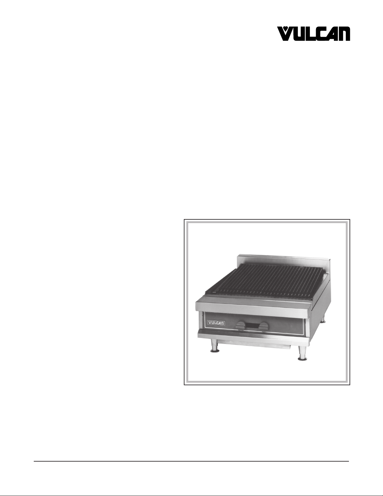
GAS CHARBROILER
MODEL
MG24CB ML-114634
CATALOG OF
VULCAN-HART COMPANY, P.O. BOX 696, LOUISVILLE, KY 40201-0696, TEL. (502) 778-2791
FORM 31016 (7-97)
Page 2
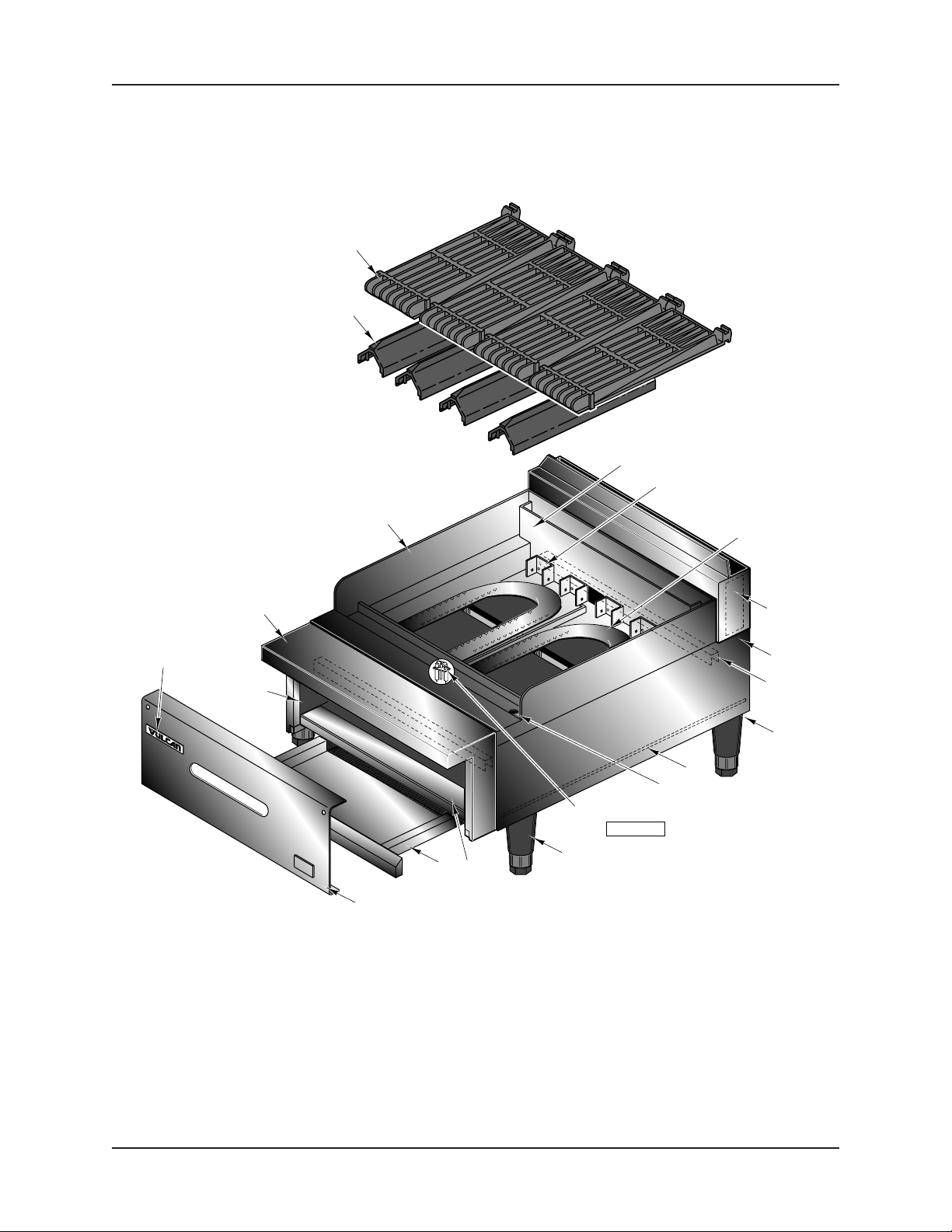
MG24CB GAS CHARBROILER REPLACEMENT PARTS
1
2
3
32
21-22
17-18
4
6
5
23 Thru 30
15-16
33
13-14
31
12
19-20
PL-52747
ON
OFF
8
34
9-10-11
7
CHARBROILER BODY
© VULCAN-HART COMPANY, 1997
– 2 –
Page 3

REPLACEMENT PARTS MG24CB GAS CHARBROILER
CHARBROILER BODY
ILLUS. PART
PL-52747 NO. NAME OF PART AMT.
1 00-422435-00001 Grate - Top ................................................................................................................................ 4
2 00-422434-00001 Radiant - Burner ........................................................................................................................ 4
3 00-422439-000G1 Main Top Assy. ..........................................................................................................................1
4 00-422012-000G1 Front Top & End Cap Assy. .......................................................................................................1
5 00-422258-000G1 Burner Tray Assy. ......................................................................................................................1
6 00-417700-00003 Nameplate 4" .............................................................................................................................1
7 00-422432-00001 Cover - Manifold ........................................................................................................................ 1
8 00-422433-000G1 Drip Pan Assy. ...........................................................................................................................1
9 00-423745-00001 Leg - Adjustable SST .................................................................................................................4
10 00-423745-00002 Leg - Adjustable PTD. ................................................................................................................4
11 00-417853-00005 Nut - Basket 1⁄2 -13 .....................................................................................................................4
12 FP-085-88 Nipple - 3⁄4 x 61⁄4 .......................................................................................................................... 1
13 00-421630-000G1 Base Frame Assy. ..................................................................................................................... 1
14 00-421435-00001 Angle - Support ..........................................................................................................................2
15 00-421434-00001 Side - Body R.H. ........................................................................................................................1
16 00-421434-00002 Side - Body L.H. .........................................................................................................................1
17 00-422255-00004 Burner - R.H. Single Row Ports .................................................................................................1
18 00-422255-00003 Burner - L.H. Single Row Ports .................................................................................................. 1
19 00-422270-00001 Pilot to Burner ............................................................................................................................1
20 00-920313 Pilot - Burner .............................................................................................................................. 1
21 00-413014-00001 Support - Radiant ....................................................................................................................... 8
22 00-424010-00001 Spacer ....................................................................................................................................... 8
23 00-421663-00001 Shield - Rear Heat ..................................................................................................................... 1
24 00-421659-00001 Shield - Rear Heat ..................................................................................................................... 1
25 00-421441-00001 Shield - Rear Heat ..................................................................................................................... 1
26 00-421445-00001 Back Splasher ............................................................................................................................ 1
27 00-417335-00001 Back Splasher ............................................................................................................................ 1
28 00-417330-00001 Back Splasher ............................................................................................................................ 1
29 00-421431-00001 Channel (For 4" Splasher) .........................................................................................................1
30 00-421504-00001 Channel - Bayonet Back (For 23" Splasher) ..............................................................................1
31 00-423691-00001 Runner - Burner Tray ................................................................................................................. 2
32 00-422257-00001 Support - Front ........................................................................................................................... 1
33 00-422428-00001 Channel - Front & Rear Top ...................................................................................................... 2
34 00-422427-00001 Bottom - Burner Box .................................................................................................................. 1
00-411766-00001 Brush ......................................................................................................................................... 1
– 3 –
Page 4

MG24CB GAS CHARBROILER REPLACEMENT PARTS
1
2
4
3
5
19
18
17
16
15
21
13-14
12
6
8-9
7
10
11
20
PL-52748
GAS CONTROLS
– 4 –
Page 5

REPLACEMENT PARTS MG24CB GAS CHARBROILER
GAS CONTROLS
ILLUS. PART
PL-52748 NO. NAME OF PART AMT.
1 FP-086-96 Pipe 3⁄4 x 24 ................................................................................................................................1
2 FP-078-88 Elbow 90 Deg. Reducing 3⁄4 to 3⁄8 ................................................................................................1
3 FP-035-46 Pipe 3⁄8 x 1 Lg. (T.B.E) ................................................................................................................1
4 00-920442 Valve .......................................................................................................................................... 1
5 FP-085-76 Pipe 3⁄8 x 2.875 ...........................................................................................................................1
6 00-920040 Thermocouple 18" ..................................................................................................................... 1
7 FP-078-88 Elbow 90 Deg. Reducing 3⁄4 to 3⁄8 ................................................................................................1
8 00-423690-00001 Tube - Flex (Gas Inlet) ...............................................................................................................1
9 00-410682-00004 Hose - Flex 4' ............................................................................................................................. 1
10 00-418052-00001 Hood .......................................................................................................................................... 2
11 00-402601-0000F Valve - Top Burner..................................................................................................................... 2
12 00-422259-00001 Manifold Assy. ........................................................................................................................... 1
13 00-010901-00042 Orifice - Spud (Nat. Gas)(3000-5000 Ft.) .................................................................................. 2
14 00-010901-00052 Orifice - Spud (L.P. Gas)(Sea Level-3000 Ft.) ........................................................................... 2
15 FP-085-53 Pipe Plug 1⁄8 ............................................................................................................................... 1
16 FP-078-88 Elbow 90 Deg. Reducing 3⁄4 to 3⁄8 ................................................................................................1
17 00-417207-00001 Bracket - Manifold ......................................................................................................................1
18 FP-085-99 Pipe 3⁄8 x 2.375 ...........................................................................................................................1
19 FP-013-11 Elbow 3⁄8 x 90 Deg. .....................................................................................................................1
20 00-420560-00001 Knob - Top Burner ..................................................................................................................... 2
21 00-423709-000G1 Pilot Bracket Assy. .....................................................................................................................1
00-411420-00001 Valve - Gas Shut Off (Shipped Loose) ...................................................................................... 1
– 5 –
Page 6

MG24CB GAS CHARBROILER REPLACEMENT PARTS
MGB SERIES MEDIUM DUTY
GAS CHARBROILERS
SERVICE
WARNING: THE CHARBROILER AND ITS PARTS ARE HOT. USE CARE WHEN OPERATING,
CLEANING OR SERVICING THE CHARBROILER.
PILOT LIGHT ADJUSTMENT
To adjust the pilot flame, remove the pilot adjustment cap to expose the adjusting screw (Fig. 1). Rotate
the adjusting screw clockwise to reduce the gas flow, and counterclockwise to increase the gas flow, to
provide a properly sized pilot flame (approximately 1/2" to 3/4" long). Replace the adjustment cap.
RED
BUTTON
PILOT
ADJUSTMENT
SCREW
PL-52472
PILOT SHUTOFF VALVE
Fig. 1
MAIN BURNER AIR SUPPLY
For efficient burner operation, it is important that a proper balance of gas volume and primary air supply
is maintained, resulting in complete combustion. Insufficient air supply results in a yellow streaming
flame. Check flames with control knob turned to HI and radiants and top grates removed. Primary air
supply is controlled by the air shutter on the front of the burner.
Loosen the hex head screws on front of the burner, and adjust the air shutter to obtain a sharp flame
without lifting. Lock the air shutter in place, tightening the screws. Repeat this procedure with all burners.
REMOVING BURNERS
To remove burners for cleaning or replacement: (a) remove the top grates; (b) remove the radiants;
(c) remove
the burners. Reverse the procedure for reassembly.
To remove the burner drawer: (a) turn off main shutoff valve; (b) disconnect union; (c) remove burner
drawer and screws and slide burner drawer forward.
– 6 –
Page 7

REPLACEMENT PARTS MG24CB GAS CHARBROILER
SERVICE TROUBLESHOOTING GUIDE
PROBLEM
Heat does not come on when control valve is
turned on.
Pilot burner will not light.
Pilot burner will not stay lit.
POSSIBLE CAUSES
1. Problem with gas valve.
2. Pilot burner is not lit.
1. Manual or safety system gas valve not
turned on.
2. Obstructed pilot orifice.
3. Pilot gas turned off at automatic pilot valve.
4. Problem with automatic valve.
1. Problem with thermocouple.
2. Thermocouple not hot enough.
3. Obstructed or wrong size pilot orifice.
4. Gas supply not purged of air.
5. Air blowing pilot out.
– 7 –
Page 8

MG24CB GAS CHARBROILER REPLACEMENT PARTS
GAS BROILER ALTITUDE/ORIFICES
DEVICE, MG24CB
ALTITUDE NATURAL GAS ALTITUDE PROPANE GAS ALTITUDE BUTANE GAS
sea level sea level sea level
-00NAT #41 (10901-41) -00PRO #54 (10901-54) -00FBU #55 (10901-55)
-02NAT #42 (10901-42) -02PRO #55 (10901-55) -02FBU #56 (10901-56)
-03NAT #43 (10901-43) -03PRO #55 (10910-55) -03FBU #57 (10901-57)
-04NAT #44 (10901-44) -04PRO #57 (10901-57) -04FBU #58 (10901-58)
-05NAT #44 (10901-44) -05PRO #58 (10901-58) -05FBU #59 (10901-59)
-06NAT #45 (10901-45) -06PRO #58 (10910-58) -06FBU #60 (10901-60)
-07NAT #46 (10901-46) -07PRO #58 (10910-58) -07FBU #61 (10901-61)
-08NAT #47 (10901-47) -08PRO #58 (10901-58) -08FBU #62 (10901-62)
-09NAT #48 (10901-48) -09PRO #62 (10901-62) -09FBU #63 (10910-63)
-10NAT #49 (10901-49) -10PRO #63 (10901-63) -10FBU #64 (10910-64)
Altitude Definitions:
Natural Gas Propane Gas Butane Gas
0 - 2000 ft. -00NAT -00PRO -00FBU
2001 - 2499 ft. -02NAT -02PRO -02FBU
2500 - 3499 ft. -03NAT -03PRO -03FBU
3500 - 4499 ft. -04NAT -04PRO -04FBU
4500 - 5499 ft. -05NAT -05PRO -05FBU
5500 - 6499 ft. -06NAT -06PRO -06FBU
6500 - 7499 ft. -07NAT -07PRO -07FBU
7500 - 8499 ft. -08NAT -08PRO -08FBU
8500 - 9499 ft. -09NAT -09PRO -09FBU
9500 - 10500 ft. -10NAT -10PRO -10FBU
ORIFICE PT. NO. ORIFICE PT. NO. ORIFICE PT. NO.
EXPORT GASES: 31FPR (foreign propane gas type G-31)
also are “-00FNA” foreign natural, “-00FPR” foreign propane, “00FBU” foreign butane - not often used.
FORM 31016 JULY 1997 PRINTED IN U.S.A.
20FNA (foreign natural gas type G-20)
25FNA (foreign natural gas type G-25)
– 8 –
 Loading...