

Page 1
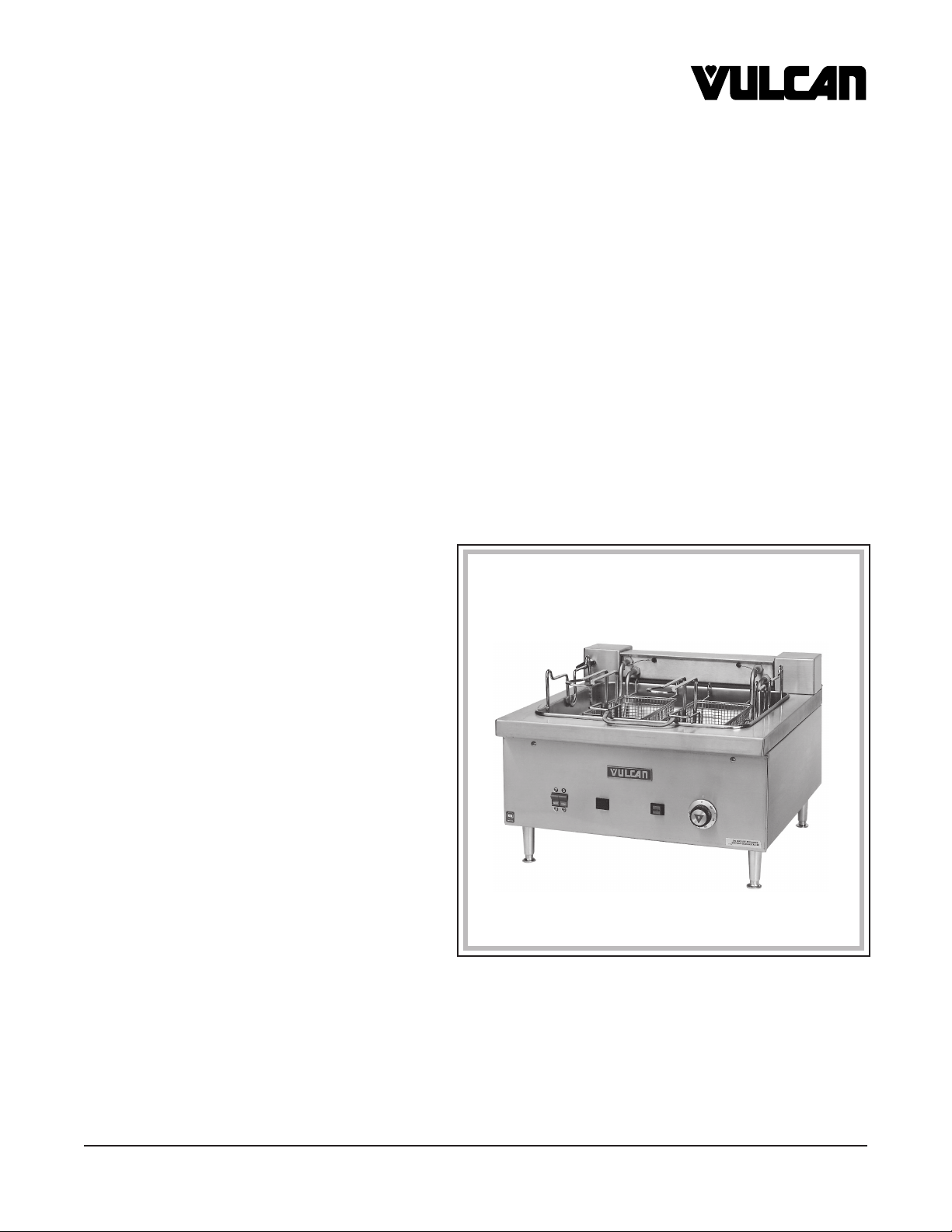
SERVICE MANUAL & CATALOG OF
ELECTRIC FRYER
MODEL
MEF24A
ML-52836 WITHOUT MELT CYCLE
ML-52837 WITH MELT CYCLE
REPLACEMENT PARTS
VULCAN-HART COMPANY, P.O. BOX 696, LOUISVILLE, KY 40201-0696, TEL. (502) 778-2791
FORM 30969 (5-97)
Page 2
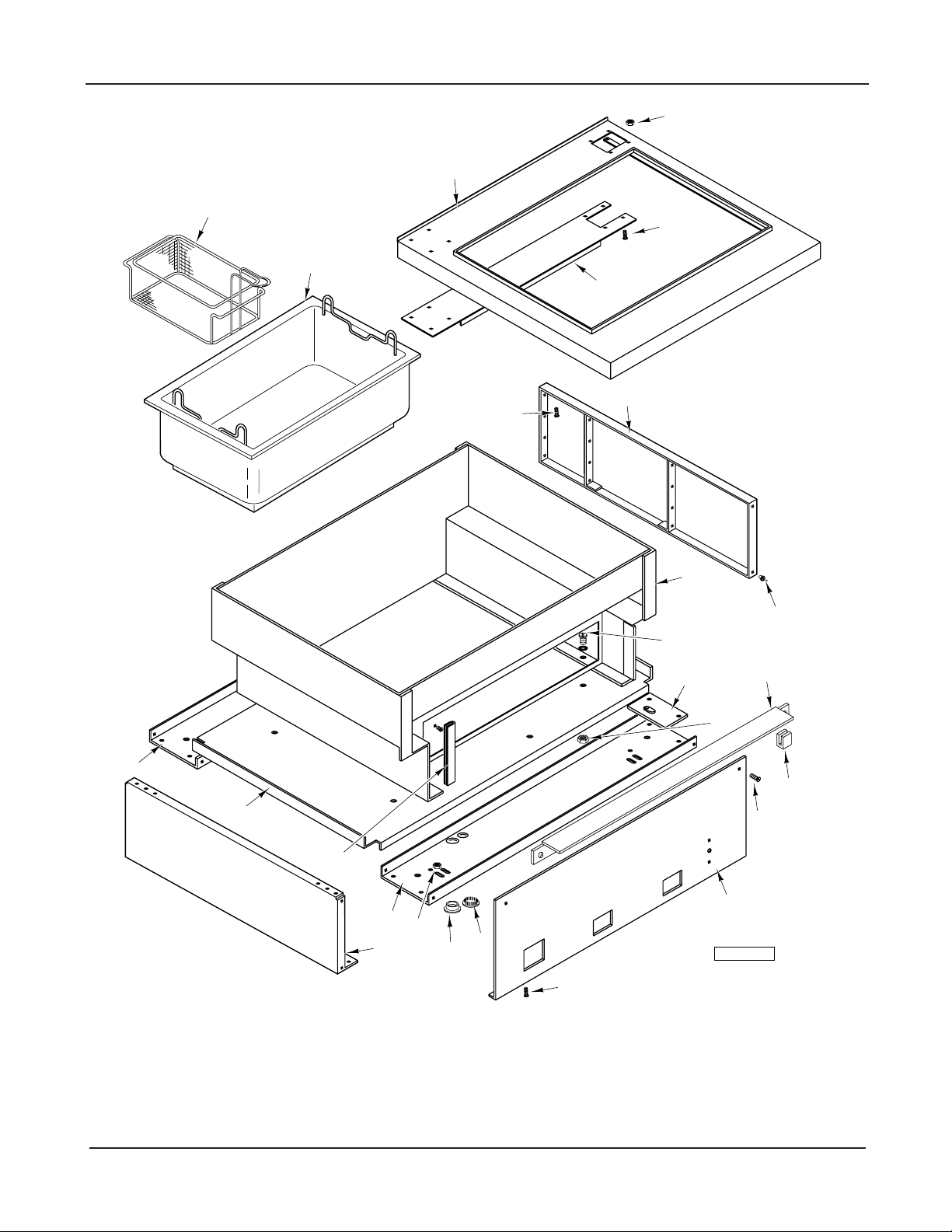
MEF24A ELECTRIC FRYER REPLACEMENT PARTS
5
4
1-2
6
3
7
8
29
10
9
11-12
28
27
26
24
23
25
FRYER BODY
22
21
20
13
15
14
16
17
18-19
PL-52122
© VULCAN-HART, 1997
– 2 –
Page 3

REPLACEMENT PARTS MEF24A ELECTRIC FRYER
FRYER BODY
ILLUS. PART
PL-52122 NO. NAME OF PART AMT.
1 00-423047-00001 Bracket-Fryer R.H. ...................................................................................................................1
2 00-423047-00002 Bracket-Fryer L.H. ....................................................................................................................1
3 00-346214-00001 Container Assy. ........................................................................................................................1
4 00-423047-00003 Panel-Top .................................................................................................................................1
5 NS-044-09 Nut Assy. 10-24 Hex Keps ....................................................................................................... 8
6 SC-067-06 Mach. Screw 10-24 x
7 00-920358-00001 Top Support Assy. ....................................................................................................................1
8 00-920001-00001 Side Panel Weldment ...............................................................................................................1
9 RS-030-08 Pop Rivet 1⁄8 x 1⁄8 SST ..............................................................................................................20
10 00-423047-00006 Liner Weldment ........................................................................................................................ 1
11 SC-053-05 Mach. Screw 10-24 x 3⁄8 Truss Hd., Slotted ..............................................................................8
12 WS-002-25 Washer .....................................................................................................................................8
13 00-920140-00001 Leg Pad Weldment ...................................................................................................................4
14 NS-044-09 Nut Assy. 10-24 Hex Keps ....................................................................................................... 8
15 00-920340 Top Cross Angle Weldment ..................................................................................................... 1
16 00-911037-00001 “U” Nut ......................................................................................................................................2
17 SD-036-71 Self-Tapping Screw 10-16 x 3⁄8, Type B, Slotted Truss Hd. ......................................................2
18 00-920552-00001 Front Panel Assy. .....................................................................................................................1
19 00-423047-00007 Front Panel Assy. (W/Melt Cycle) ............................................................................................1
20 SC-053-05 Mach. Screw 10-24 x 3⁄8 Truss Hd., Slotted ..............................................................................2
21 00-911510-00006 Plug 7⁄8" Vent ............................................................................................................................. 2
22 00-920371 Plug .......................................................................................................................................... 1
23 NS-044-09 Nut Assy. 10-24 Hex Keps ....................................................................................................... 4
24 00-423047-00011 Channel-Front & Rear .............................................................................................................. 1
25 00-920001-00001 Side Panel Weldment ...............................................................................................................1
26 00-423047-00002 Bracket-Fryer L.H. ....................................................................................................................2
27 00-423047-00013 Cover-Bottom ........................................................................................................................... 1
28 00-423047-00011 Channel-Front & Rear .............................................................................................................. 1
29 SC-053-05 Mach. Screw 10-24 x 3⁄8 Truss Hd., Slotted ..............................................................................2
1
⁄2 Hex Hd. ..............................................................................................8
– 3 –
Page 4
MEF24A ELECTRIC FRYER REPLACEMENT PARTS
13
2
1
40
3
41
12
14
15
19
20
10-11
21
18
16
17
4
5
6
7
8
9
37
38
39
36
27
35
34
33
32
ELECTRICAL COMPONENTS
25
28
29
26
30
31
22
23
24
PL-52123
– 4 –
Page 5

REPLACEMENT PARTS MEF24A ELECTRIC FRYER
ELECTRICAL COMPONENTS
ILLUS. PART
PL-52123 NO. NAME OF PART AMT.
1 00-804752 Clamp-Tube .............................................................................................................................. 3
2 NS-011-07 Mach. Nut 6-32 Hex .................................................................................................................3
3 SC-114-83 Mach. Screw 6-32 x
4 SC-109-10 Mach. Screw 6-32 x 3⁄8 Pan Hd. ................................................................................................2
5 00-801128 Clamp-Thermostat Bulb ........................................................................................................... 2
6 00-801128 Clamp-Thermostat Bulb ........................................................................................................... 2
7 NS-011-07 Mach. Nut 6-32 Hex .................................................................................................................2
8 00-920343 Breaker-Circuit ......................................................................................................................... 1
9 00-920121 Label-Reset .............................................................................................................................. 2
10 00-417700-00003 Nameplate ................................................................................................................................1
11 NS-047-68 Lock Nut 1⁄8 ...............................................................................................................................2
12 00-920349 Thermostat ............................................................................................................................... 1
13 00-920350 Spring-Thermostat ....................................................................................................................1
14 PB-004-69 Plug-Hole .................................................................................................................................. 1
15 00-920394 Knob-Control ............................................................................................................................1
16 00-920477 Light-Amber Indicator ............................................................................................................... 1
17 00-920476 Switch-Lighted Red Pushbutton ............................................................................................... 1
18 SC-109-10 Mach. Screw 6-32 x 3⁄8 Pan Hd. ................................................................................................4
19 00-805995 Label ......................................................................................................................................... 1
20 00-920373 Contactor-Mounting Panel ........................................................................................................1
21 00-920545 Label-Connection ..................................................................................................................... 1
22 NS-044-09 Nut Assy. 10-24 Hex Keps ....................................................................................................... 2
23 SC-053-05 Mach. Screw 10-24 x 3⁄8 Truss Hd., Slotted ..............................................................................3
24 00-920541 Strip - Terminal .........................................................................................................................1
25 00-825126-00040 Block-Terminal ......................................................................................................................... 1
26 FE-023-68 Lug-Solderless .........................................................................................................................1
27 00-920524 Label ......................................................................................................................................... 1
28 00-920544 Label Fuse Warning .................................................................................................................1
29 00-805780 Marker-Supply .......................................................................................................................... 1
30 00-908805 Label-Ground Warning ............................................................................................................. 1
31 00-825368 Plate-Serial Number ................................................................................................................. 1
32 SD-036-71 Self-Tapping Screw 10-16 x 3⁄8, Type B, Slotted Truss Hd. ......................................................2
33 00-805782 Label-Disconnect Power .......................................................................................................... 1
34 00-348189-00004 Label-Stock ..............................................................................................................................1
35 00-920378-00010 Label-Wiring Diagram ............................................................................................................... 1
36 00-920342 Panel-Rear ............................................................................................................................... 1
37 00-920543 Fuse ......................................................................................................................................... 4
38 00-911510-00006 Plug 7⁄8" Vent ............................................................................................................................. 2
39 00-920542 Block-Fuse ............................................................................................................................... 2
40 00-920360 Contactor-Magnetic .................................................................................................................. 2
41 SC-053-05 Mach. Screw 10-24 x 3⁄8 Truss Hd., Slotted ..............................................................................3
00-423047-00009 Switch-Melt ...............................................................................................................................1
00-423047-00008 Switch-Pushbutton (Melt) ......................................................................................................... 1
00-423047-00010 Switch-Infinite (Melt) .................................................................................................................1
1
⁄4 Pan Hd. ................................................................................................3
– 5 –
Page 6

MEF24A ELECTRIC FRYER REPLACEMENT PARTS
25
23
24
22
21
20
19
4
2
1
15-16
17
18
3
14
5
6
7-8
9
11
10
13
PL-52124
HEATING ELEMENTS
– 6 –
12
Page 7

REPLACEMENT PARTS MEF24A ELECTRIC FRYER
HEATING ELEMENTS
ILLUS. PART
PL-52124 NO. NAME OF PART AMT.
1 00-920370 Cover-Pivotal Head .................................................................................................................. 1
2 00-920365 Gasket-Pivotal Head ................................................................................................................ 1
3 SC-053-05 Mach. Screw 10-24 x 3⁄8 Truss Hd., Slotted ..............................................................................2
4 00-920467 Cover-End Post Back ............................................................................................................... 1
5 00-920666-00001 Post-Thermostat End ...............................................................................................................1
6 00-920468 Gasket-End Post ...................................................................................................................... 1
7 00-920125-00010 Element (6000 W, 208V) ..........................................................................................................2
8 00-920125-00011 Element (6000 W, 240V) ..........................................................................................................2
9 00-920472-00001 Support-Element ......................................................................................................................2
10 SC-119-64 Mach. Screw 8-32 x 1 Slotted Truss Hd. ..................................................................................2
11 00-423047-00015 Handle-Element Lift ..................................................................................................................1
12 SC-053-05 Mach. Screw 10-24 x 3⁄8 Truss Hd., Slotted ..............................................................................8
13 00-920474 Bar-Element Clamp .................................................................................................................. 1
14 00-920547 Clamp-Capillary Bulb ................................................................................................................1
15 00-804735 Switch-High Limit ......................................................................................................................1
16 00-911033-00023 Screw-Sheet Metal 7 x 3⁄8 .........................................................................................................2
17 00-920662-00001 Pivot-Head Weldment ..............................................................................................................1
18 00-345689-00002 Grommet ..................................................................................................................................2
19 00-920402 Knob-Pull ..................................................................................................................................1
20 00-920468 Gasket-End Post ......................................................................................................................1
21 00-920368 Body-Plunger ............................................................................................................................ 1
22 NS-047-64 Stop Nut 5⁄8-18 Hex ...................................................................................................................1
23 00-920365 Gasket-Pivotal Head ................................................................................................................ 1
24 00-920369 Plunger ..................................................................................................................................... 1
25 00-920660 Post-Locking End ..................................................................................................................... 1
– 7 –
Page 8

MEF24A ELECTRIC FRYER REPLACEMENT PARTS
MEF24A ELECTRIC MEDIUM DUTY
FRYER
SERVICE
WARNING: HOT OIL AND PARTS CAN CAUSE BURNS. USE CARE WHEN OPERATING, CLEANING OR
SERVICING THE FRYER.
WARNING: SPILLING HOT OIL CAN CAUSE SEVERE BURNS. DO NOT MOVE FRYER WITHOUT DRAINING
ALL OIL FROM THE TANK.
WARNING: DISCONNECT ELECTRICAL POWER SUPPLY AND PLACE A TAG AT THE DISCONNECT
SWITCH TO INDICATE THAT YOU ARE WORKING ON THE CIRCUIT BEFORE PERFORMING ANY SERVICE.
CHECKING THERMOSTAT CALIBRATION
The fryer thermostat is carefully calibrated at the factory so that dial settings match actual frying compound
temperatures. Field recalibration is seldom necessary, unless the fryer has been mishandled in transit or
abused. Recalibration should not be resorted to unless considerable experience with cooking results definitely
proves that the control is not maintaining the temperature to which the dial is set.
1. To check frying compound temperatures when recalibrating, use a precision test instrument, or a good
grade mercury thermometer. Fill fry tank with frying compound to "FULL" mark.
2. Check frying compound temperature at the center of the tank, approximately 1" to 11/2" below surface of
frying compound.
3. Turn dial of thermostat being checked to the 350°F mark.
4. Allow temperature to stabilize, or until thermostat cycles to OFF three times after starting with cold frying
compound. With power ON, read highest and lowest frying compound temperature, as thermostat cycles
through at least two cycles. Average the reading.
5. Thermostat should be recalibrated if temperature reading is not within 10 degrees of the control knob
setting (350°F plus or minus 10°F). If recalibration is required, continue with steps 6, 7, 8 and 9.
6. Remove control knob by grasping outer edge and pulling straight out, without twisting or turning.
7. Hold thermostat dial shaft "B" (Fig. 1) stationary with pliers, and with a screwdriver, turn screw "A" (Fig. 1)
clockwise to obtain a lower temperature, or counterclockwise for higher temperature. Each 1/4 turn (90°
rotation) of screw "A" represents 18°F.
8. Replace thermostat control knob.
9. Recheck thermostat as in Steps 4 and 5 above. If the frying compound temperature is not within 20
degrees of dial setting (350°F plus or minus 20°F), it means that the sensing element is inoperative, and
the thermostatic control should be replaced.
– 8 –
Page 9

REPLACEMENT PARTS MEF24A ELECTRIC FRYER
INCREASE
DIAL SHAFT "B"
DECREASE
1/4 TURN
"A"
"A" SCREW
PL-52688
Fig. 1
REPLACING RED ON-OFF SWITCH, YELLOW CYCLING LIGHT OR CIRCUIT BREAKER. (ALSO WHITE
"MELT ON" SWITCH AND MELT CYCLE CONTROL ASSEMBLY FOR MELT CYCLE OPERATION)
1. Remove thermostat control knob by grasping outer edge and pulling straight out, without twisting or turning.
2. Remove two screws at top of front panel. Pull top edge to open.
3. Disconnect leads to switch, light or circuit breaker, and remove the damaged component. Mark disconnected
leads to identify them.
4. Mount the new circuit breaker (or melt cycle control) with fasteners provided. The new switch, or light, is
snapped into place from the front of the panel.
5. Connect leads to corresponding terminals on new component. Check completed circuit against circuit
diagram on rear panel.
6. Reverse steps 1 and 2 to close front panel.
REPLACING MAGNETIC CONTACTOR, TERMINAL BLOCK, GROUND LUG OR AUXILIARY TERMINAL
BLOCK
1. Remove four screws securing rear panel to fryer. Let the rear panel fall down straight before pulling it out.
2. Disconnect leads to the damaged component.
3. Connect the leads to corresponding terminal on the new component.
4. Remove screws securing the damaged component to the mounting panel.
– 9 –
Page 10

MEF24A ELECTRIC FRYER REPLACEMENT PARTS
5. Remove the damaged component and install a new component in the same position.
6. Check completed circuit against circuit diagram on rear panel.
7. Mount the rear panel and put fryer in operation.
REPLACING BLOWN FUSES OR FUSE BLOCK
1. Remove four screws securing rear panel to fryer. Let rear panel fall down straight before pulling it out.
2. Remove damaged fuses and replace with 40 Ampere one time fuse.
3. To replace fuse block, remove fuses and disconnect wire leads to the damaged fuse block. Mark disconnected
leads to identify them.
4. Replace new fuse block in the same position.
5. Connect leads to corresponding terminal on new fuse block. Check completed circuit against circuit diagram
on rear panel.
REPLACING ELEMENT
1. Remove screws securing pivotal head cover to pivotal head. Remove pivotal head cover and gasket.
2. Lift up the elements to drain position.
3. Remove thermostat bulb and capillary tube clamps.
4. Remove element support assembly.
5. Disconnect leads to element and mark them for identification.
6. Remove the element retaining nuts inside the pivotal head.
7. Remove element. Mount the new element and reverse steps 1 through 6 to reassemble.
REPLACING HI-LIMIT THERMOSTAT
1. Remove screws securing pivotal head cover to pivotal head. Remove pivotal head cover and gasket.
2. Remove Hi-Limit thermostat bulb and capillary tube clamps from element.
3. Dislodge capillary bushing from hole in pivotal head.
4. Remove bushing and thread the thermostat capillary and bulb through hole in pivotal head.
5. Disconnect leads to the damaged Hi-Limit thermostat and transfer them to corresponding leads on new
thermostat.
6. Remove screws securing the thermostat.
7. Secure new Hi-Limit thermostat with screws and reverse steps 1 through 4 to reassemble.
– 10 –
Page 11

REPLACEMENT PARTS MEF24A ELECTRIC FRYER
REPLACING CYCLING THERMOSTAT
1. Remove thermostat control knob by grasping outer edge and pulling straight out without twisting or turning.
2. Remove two screws at top of front panel. Pull top edge to open.
3. Remove four screws securing rear panel to fryer. Let rear panel fall down straight before pulling it out.
4. Remove screws securing pivotal head cover to pivotal head. Remove pivotal head cover and gasket.
5. Remove cover on back of end post, located on right rear corner of fryer.
6. Remove Hi-Limit thermostat bulb and capillary tube clamps from element.
7. Dislodge capillary bushing from hole in pivotal head.
8. Remove bushing and thread the thermostat capillary and bulb through hole in pivotal head.
9. Disconnect nuts securing thermostat coil to end post and to pivotal head. Both are accessible from rear of
end post.
10. Disconnect leads to the damaged thermostat and mark them for identification.
11. Remove screws securing thermostat to front panel.
12. Maneuver the thermostat to rear of fryer (through right side passage), and then into the right side end post
(through opening on top panel.
13. Remove thermostat, along with bulb and capillary, from the opening on back of right side end post.
14. Wind thermostat coil (supplied with new thermostat) around capillary of new thermostat at approximately
the same position from bulb as on the damaged thermostat. The thermostat coil should cover approximately
11" to 12" of capillary length.
15. Wrap the portion of thermostat capillary which is covered by the thermostat coil into approximately two
turns of 11/2" to 2" diameter.
16. Reassemble the thermostat by reversing steps 1 through 13.
Required replacement parts should be ordered by part numbers as shown on parts list in this manual.
– 11 –
Page 12

MEF24A ELECTRIC FRYER REPLACEMENT PARTS
FORM 30969 MAY 1997 PRINTED IN U.S.A.
– 12 –
 Loading...