

Page 1
SERVICE & PARTS MANUAL
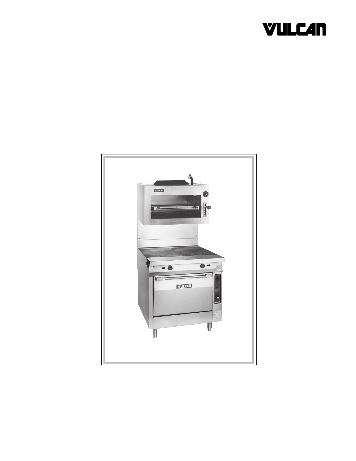
FOR GAS INFRARED BROILER
MODEL IR34
VULCAN-HART COMPANY, P.O. BOX 696, LOUISVILLE, KY 40201-0696, TEL. (502) 778-2791
FORM 30813 (1-93)
Page 2

IR34 REPLACEMENT PARTS
SERVICE VALVE LUBRICATION
SERVICING THE MANIFOLD PIPE AND INTERNAL GAS CONNECTIONS
MAIN GAS MANIFOLD & INTERNAL GAS CONNECTIONS
1. Remove the control knob from the front of the unit.
2. Turn off main gas supply and disconnect unit manifold pipe fittings.
3. Remove five (5) screws from front frame of unit.
4. Remove front frame from unit.
5. Remove five screws from the top right hand body side.
6. Remove the right hand body side from the unit.
7. The manifold pipe and internal gas connections will be serviceable from this point.
8. To reinstall, reverse steps 1 through 6.
BURNER REPLACEMENT:
1. Standing in front of the unit remove (2) 7⁄16" nuts holding the Infrared
burner to the support bracket in the Broiler compartment.
2. Slide the burner assembly slightly (carefully, so as not to ram the pilot
nozzle) through the 3" venturi hole in the right hand body side lining.
3. Angle the square end of burner assembly towards the front of the
unit and remove it from the Broiler compartment.
4. Reinstall the new burner by reversing steps 1 through 3.
SERVICE VALVE LUBRICATION
1. Loosen the set screw on the control knob as shown in Detail H.
2. Remove the control knob.
3. Insert a screwdriver and remove the two screws on the front of the
control valve (Detail I).
4. After the screws are removed, carefully pull out on the valve stem and
remove it for lubrication (Detail J).
DETAIL H
DETAIL I
5. To reinstall reverse steps 1 through 4.
DETAIL J
– 2 –
Page 3
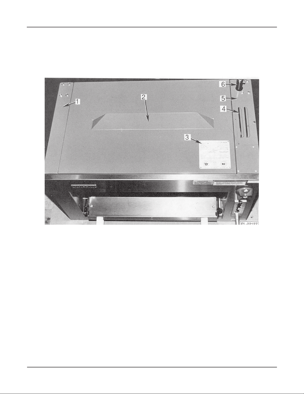
REPLACEMENT PARTS IR34
TOP SECTION
ILLUS. PART
PL-22127 NO. NAME OF PART AMT.
1 414931-G1 Body Side L.H. (Painted) .................................................................................................................. 1
2 414936-G1 Body Top .......................................................................................................................................... 1
3 411955-1 Rating Plate ...................................................................................................................................... 1
4 415138-1 Access Panel Cover ......................................................................................................................... 1
5 414932-G1 Body Side R.H. (Painted) ................................................................................................................. 1
6 417183-G2 Manifold Assembly ........................................................................................................................... 1
– 3 –
Page 4

IR34 REPLACEMENT PARTS
FRONT SECTION
ILLUS. PART
PL-22120 NO. NAME OF PART AMT.
1 407727-3 Control Knob .................................................................................................................................... 1
2 414819-1 Red Plastic Ball Handle .................................................................................................................... 1
3 414951-G1 Grid Assembly .................................................................................................................................. 1
4 414946-G1 Grid Carriage Assembly ................................................................................................................... 1
5 406053-1 Index Plate ....................................................................................................................................... 1
6 409790-3 Post - Handle (R.H.) ......................................................................................................................... 1
7 409790-4 Post - Handle (L.H.) ......................................................................................................................... 1
8 408246-3 Grid Handle ...................................................................................................................................... 1
9 414938-1 Drip Pan ........................................................................................................................................... 1
10 414939-G1 Drip Pan Insert Assembly ................................................................................................................. 1
11 414940-G1 Handle Assembly (Drip Pan) ............................................................................................................ 1
12 408279-22 Regulator (Natural) ........................................................................................................................... 1
13 408279-21 Regulator- Pressure (LP & Butane Gas) .......................................................................................... 1
14 FP-13-22 Elbow 3⁄4 x 90 Deg ............................................................................................................................ 1
15 417183-G2 Manifold Assembly ........................................................................................................................... 1
16 415116-3 Mounting Bracket - Right - Med. Duty Ranges ................................................................................. 1
17 415116-1 Mounting Bracket - Left - Med. Duty Ranges ................................................................................... 1
18 415116-4 Mounting Bracket - Right (SS) - Med. Duty Ranges ........................................................................ 1
19 415116-2 Mounting Bracket - Left (SS) - Med. Duty Ranges ........................................................................... 1
20 415138-1 Access Panel Cover ......................................................................................................................... 1
21 415138-2 Access Panel Cover (SS) ................................................................................................................. 1
22 415137-1 Indicator Decal ................................................................................................................................. 1
417211-1 Mounting Brackets For Heavy Duty Ranges .................................................................................... 2
– 4 –
Page 5

REPLACEMENT PARTS IR34
HEATING SECTION
ILLUS. PART
PL-22124 NO. NAME OF PART AMT.
1 414754-3 Burner Assembly .............................................................................................................................. 1
2 409125-10 Pilot Assembly (Natural) ................................................................................................................... 1
3 409125-12 Pilot Assembly (Propane) ................................................................................................................. 1
4 419547-G1 Inner Right Body Side ...................................................................................................................... 1
5 419546-G1 Inner Left Body Side ......................................................................................................................... 1
6 414927-1 Inner Body Back ............................................................................................................................... 1
– 5 –
Page 6

IR34 REPLACEMENT PARTS
UNDER SECTION
ILLUS. PART
PL-22125 NO. NAME OF PART AMT.
1 406046-1 Sleeve - Handle ................................................................................................................................ 1
2 406350-1 Handle Spring .................................................................................................................................. 1
2a NS-047-78 Nut for Handle Spring....................................................................................................................... 1
3 417865-1 Turnbuckle (36") ............................................................................................................................... 2
4 417871-1 Spring - Door .................................................................................................................................... 2
5 402570-1 Eye Bolt ............................................................................................................................................ 2
405655-4 Roller Bearing (Grid) ........................................................................................................................ 4
405655-1 Ball Bearing (Grid Carriage) ............................................................................................................. 4
– 6 –
Page 7

REPLACEMENT PARTS IR34
MANIFOLD & INTERIOR SIDE
ILLUS. PART
PL-22126 NO. NAME OF PART AMT.
1 407789-1 Control Valve .................................................................................................................................... 1
2 FP-86-50 Comp. Fitting 3⁄8 F x 7⁄16 CC (Elbow) .................................................................................................. 1
3 417189-1 Burning Tubing ................................................................................................................................. 1
4 404079-A32 Burner Nozzle (Natural) ................................................................................................................... 1
4a 010901-32 Orifice Nat ........................................................................................................................................ 1
4b 010901-53 Orifice LP ......................................................................................................................................... 1
5 417183-G2 Manifold Assembly ........................................................................................................................... 1
6 404193-1 Valve - Pilot ...................................................................................................................................... 1
7 417188-1 Pilot Tube ......................................................................................................................................... 1
8 414943-1 Upper Arm Assembly ....................................................................................................................... 2
9 419930-G2 Grid Carriage Lift Assembly, Left ..................................................................................................... 1
10 419931-G1 Grid Carriage Lift Assembly, Right ................................................................................................... 1
11 419929-G1 Lower Arm Assembly ....................................................................................................................... 1
N/S 408279-20 Regulator Nat ................................................................................................................................... 1
N/S 408279-21 Regulator LP .................................................................................................................................... 1
– 7 –
Page 8

THIS
PAGE
INTENTIONALLY
LEFT
BLANK
 Loading...