

Page 1
SERVICE AND PARTS MANUAL
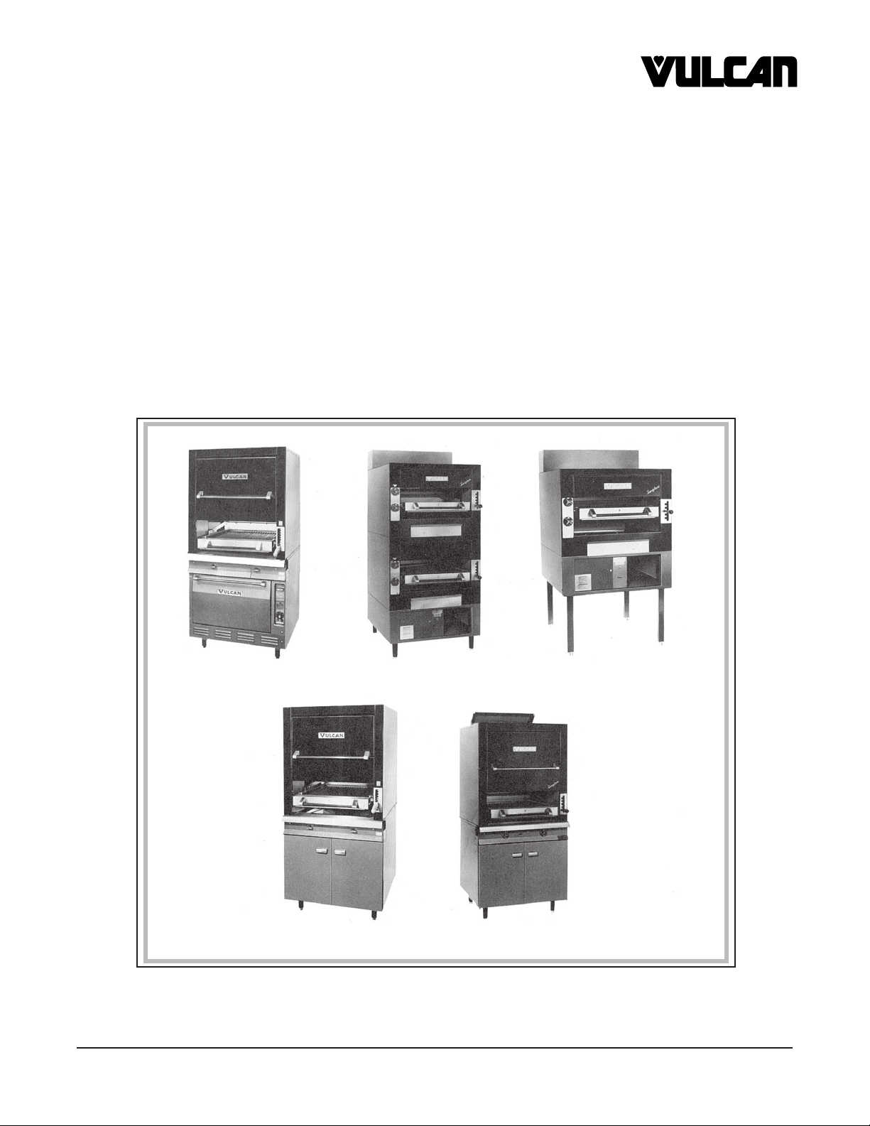
FOR HEAVY DUTY GAS BROILERS
CERAMIC MODELS SUNGLOW MODELS
MODEL FORMERLY MODEL FORMERLY
HCB040 7840AL IR1 IR-71P
HCB44 7844L IR2 IR-72P
HMCB44 M7844L IR44 IR-744P
HCB1 CB-1L
HCB2 CB-2L
Model HCBO40
Model HCB44
VULCAN-HART COMPANY, P.O. BOX 696, LOUISVILLE, KY 40201-0696, TEL. (502) 778-2791
FORM 30534 (02-90) Formerly 114517
Model IR-2
Model IR44
Model IR1
Page 2

GAS BROILERS SERVICE & PARTS
IMPORTANT
OPERATING, INSTALLING AND SERVICE PERSONNEL
Operating information for this equipment has been prepared for use by qualified and/autho-
rized operating personnel.
All installation and service on this equipment is to be performed by qualified, certified, licensed and/
authorized installation or service personnel, with the exception of any part marked with a in front of the
part number.
Service may be obtained by contacting the Factory Service Department, Factory Representative or Local
Service Agency.
DEFINITIONS
QUALIFIED AND/OR AUTHORIZED OPERATING PERSONNEL
Qualified or authorized operating personnel are those who have carefully read the information in this
manual and are familiar with the equipment’s functions or have had previous experience with the
operation of the equipment covered in this manual.
QUALIFIED INSTALLATION PERSONNEL
Qualified installation personnel are individuals, a firm, corporation or company which either in person
or through a representative are engaged in, and are responsible for:
1. The installation of gas piping from the outlet side of the gas meter, or the service regulator when the
meter is not provided, and the connection and installation of the gas appliance. Qualified installation
personnel must be experienced in such work, be familiar with all precautions required, and have
complied with all requirements of state or local authorities having jurisdiction. Reference in the United
States of America - National Fuel Gas Code ANSI Z223.1 (Latest Edition). In Canada - Canadian
Standard CAN/CGA-B149.1 NAT. GAS (Latest Edition) or CAN/CGA-B149.2 PROPANE GAS
(Latest Edition).
2. The installation of electrical wiring from the electric meter, main control box or service outlet to the
electric appliance. Qualified installation personnel must be experienced in such work, be familiar
with all precautions required, and have complied with all requirements of state or local authorities
having jurisdiction. Reference: In the United States of America - National Electrical Code ANSI NFPA
No. 70 (Latest Edition). In Canada - Canadian Electric Code Part 1 CSA-C22.1 (Latest Edition).
3. The installation of steam piping from the source of supply to the service inlet of the appliance.
Qualified installation personnel must be experienced in such work, be familiar with all precautions
required, and have complied with all requirements of state or local authorities having jurisdiction.
QUALIFIED SERVICE PERSONNEL
Qualified service personnel are those who are familiar with Vulcan equipment who have been endorsed
by the Vulcan-Hart Corporation. All authorized service personnel are required to be equipped with a
complete set of service and parts manuals and stock a minimum amount of parts for Vulcan equipment.
– 2 –
Page 3
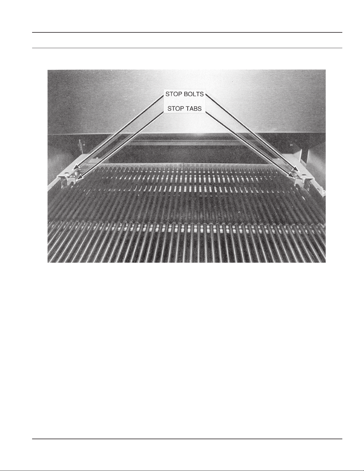
STOP BOLT - INFORMATION
SERVICE & PARTS GAS BROILERS
IMPORTANT
STOP BOLTS MUST BE IN POSITION FOR
SAFE OPERATION OF GRID
IF DAMAGED OR MISSING REPLACE AT ONCE
DO NOT OPERATE GRID WITHOUT BOLTS
Two (2) broiler grid 1⁄4-20 stop bolts and nuts are supplied with each broiler grid to ensure
that the grid is not accidentally pulled completely from the broiler section while hot. One (1)
stop bolt and nut is mounted to the grid carriage RT. and LT. HD. side member through a .281
diameter hole directly in front of the grid stop tab. The stop nuts and bolts are screwed tightly
against the side members and are properly adjusted extending approximately 1⁄2" below the
stop tab as shown in the above photo.
– 3 –
Page 4

GAS BROILERS SERVICE & PARTS
GENERAL INSTRUCTIONS (ALL BROILERS)
PREHEATING
CONVENTIONAL AND SUNGLOW UNITS
It is not necessary to preheat the broiler before using nor
is it necessary to keep the gas on a low setting when not
in use. Broiling temperatures are reached within 90 seconds. Burner life will be extended if the practice of turning
the burners off between cooking periods is practiced.
GRID POSITIONING AND GAS SETTING:
Each operator will find the optimum grid position and gas
setting desired for various products. However, it is recommended that gas input should be reduced first when lower
grid temperatures are desired. Further reduction in grid
temperatures, if necessary, can then be obtained by
lowering the grid position, to any one of the several grid
positions.
To relocate grid position, grasp the grid lever arm and push
the handle to the right of the index plate. (HCB1, HCB2 and
IR units) (Opposite on HCB040, HCB44 and HMCB44
units). Glide the arm up or down to the desired location.
Push the lever arm handle to the left and lock the arm into
the proper index plate position.
LIGHTING INSTRUCTIONS
(HCB44, HCB040, HMCB44)
1. Remove AuGratin oven bottom, baffle and burner box
cover.
2. Remove oven bottom and baffles - HCB040 only.
3. Remove manifold panel.
4. Turn on the gas supply and check for leaks using a
soap and water solution or other acceptable method.
WARNING: MATCHES, CANDLES OR OTHER
SOURCES OF IGNITION SHOULD NOT BE USED
FOR THIS PURPOSE.
5. Place the ceramics with the projections down, to the
rear of broiler burners. The lugs on the burners will
properly position. The ceramics are sized at the factory.
6. Replace the AuGratin oven baffle and bottom, but
leave the burner box cover off. Turn on the gas valve
and allow the air in the line to be exhausted. When gas
begins to flow, turn the gas valve off and wait 5 minutes
before lighting pilots and burner with a taper. The
burner flame should be sharp when the unit is cold with
a blue cone of flame about 3⁄4" long on Natural Gas and
1
⁄2" long on Propane Gas. The flame will soften out and
curl around the ceramics as the broiler gets hot. The
length of the flame is determined by the adjustment of
the nozzle. The sharpness of the flame is determined
by the air shutter adjustment.
7. Adjust broiler pilots at the pilot valve on the left end of
the pilot manifold pipe. Adjust the flame to approximately 3/4" long. Replace the burner box front.
8. Adjust the oven pilot and burner on Model HCB040.
See heat control instructions for proper adjustment of
minimum bypass setting.
9. Replace the manifold panel and other parts that had
been removed.
CARBONIZATION OF CERAMICS
If the ceramics take on a black sooty accumulation, the
burners are receiving an insufficient amount of air. The
cure is to open the air shutters further. If carbonization
occurs during initial adjustment, it will burn off as soon as
proper adjustment is achieved.
BURNER PERFORMANCE
If, after a period of satisfactory operation, the burner flame
characteristics should change or the length of burner
flame should be reduced, either the air mixer opening or
the gas valve orifice has become restricted. The burners
should be cleaned every 60 days or more often as
required.
OVEN LIGHTING INSTRUCTIONS (HCB040)
1. If the pilot is out, turn the burner “off”, wait 5 minutes
before relighting.
2. Depress the button and ignite the pilot, hold 30 seconds until pilot remains “on”.
3. Turn knob to “on” for oven burner, set the thermostat
dial to desired temperature.
4. For a complete shutdown, turn the knob to “off” and the
pilot to “on”.
The above instructions may also be found on the oven
control panel of the unit.
– 4 –
Page 5
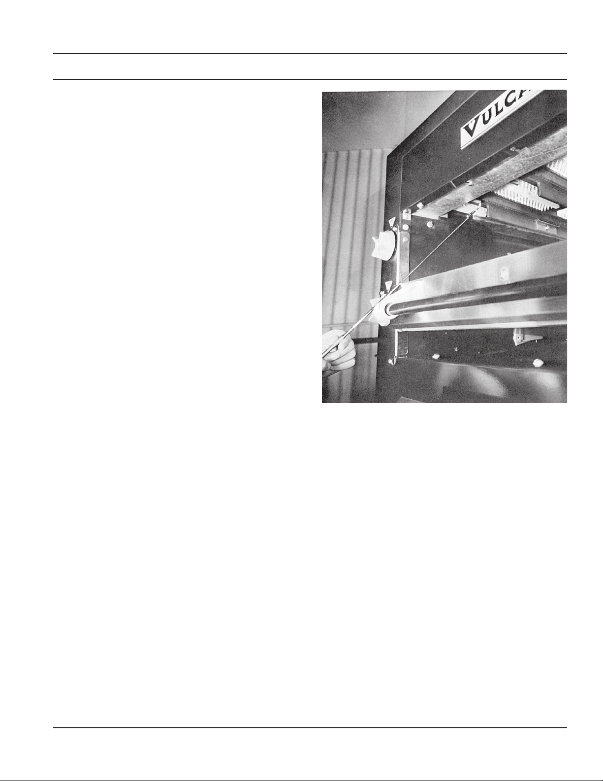
MODEL NUMBERS HCB1 and HCB2
LIGHTING INSTRUCTIONS
1. Remove burner box front cover and turn on the gas
supply and check for leaks using a soap and water
solution or other acceptable method.
WARNING: MATCHES, CANDLES OR OTHER
SOURCES OF IGNITION SHOULD NOT BE USED
FOR THIS PURPOSE.
2. Place the ceramics with the projections down, to the
rear of broiler burners. The lugs on the burners will
properly position. The ceramics are sized at the factory.
3. Turn on the gas valve and allow the air in the line to be
exhausted. When gas begins to flow, turn the gas valve
off and wait 5 minutes before lighting the pilots and
burner with a taper. The burner flame should be sharp,
when the unit is cold, with a blue cone of flame about
3
⁄4" long on Natural Gas and 1⁄2" long on Propane Gas.
The flame will soften out and curl around the ceramics
as the broiler gets hot. The length of the flame is
determined by the adjustment of the nozzle. The
sharpness of the flame is determined by the air shutter
adjustment. (See Detail A)
SERVICE & PARTS GAS BROILERS
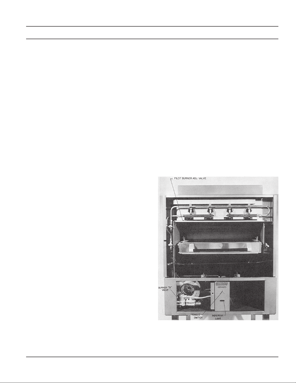
PILOT BURNER ADJUSTMENT
Turn the pilot burner valve on. The valve is located in the
lower compartment. Each burner is provided with a standing pilot burner. Adjust the pilot flame to approximately 3⁄4"
flame height. The adjusting valve is installed in the inlet of
the pilot burner manifolding located behind the removable
front panel above the grid area.
CARBONIZATION OF CERAMICS
If the ceramics take on a black sooty accumulation, the
burners are receiving an insufficient amount of air. The
cure is to open the air shutters further. If carbonization
occurs during initial adjustment, it will burn off as soon as
proper adjustment is achieved.
BURNER PERFORMANCE
If, after a period of satisfactory operation, the burner flame
characteristics should change or the length of burner
flame should be reduced, either the air mixer opening or
the gas valve orifice has become restricted. The burners
should be cleaned every 60 days or more often as
required.
DETAIL A
– 5 –
Page 6
GAS BROILERS SERVICE & PARTS
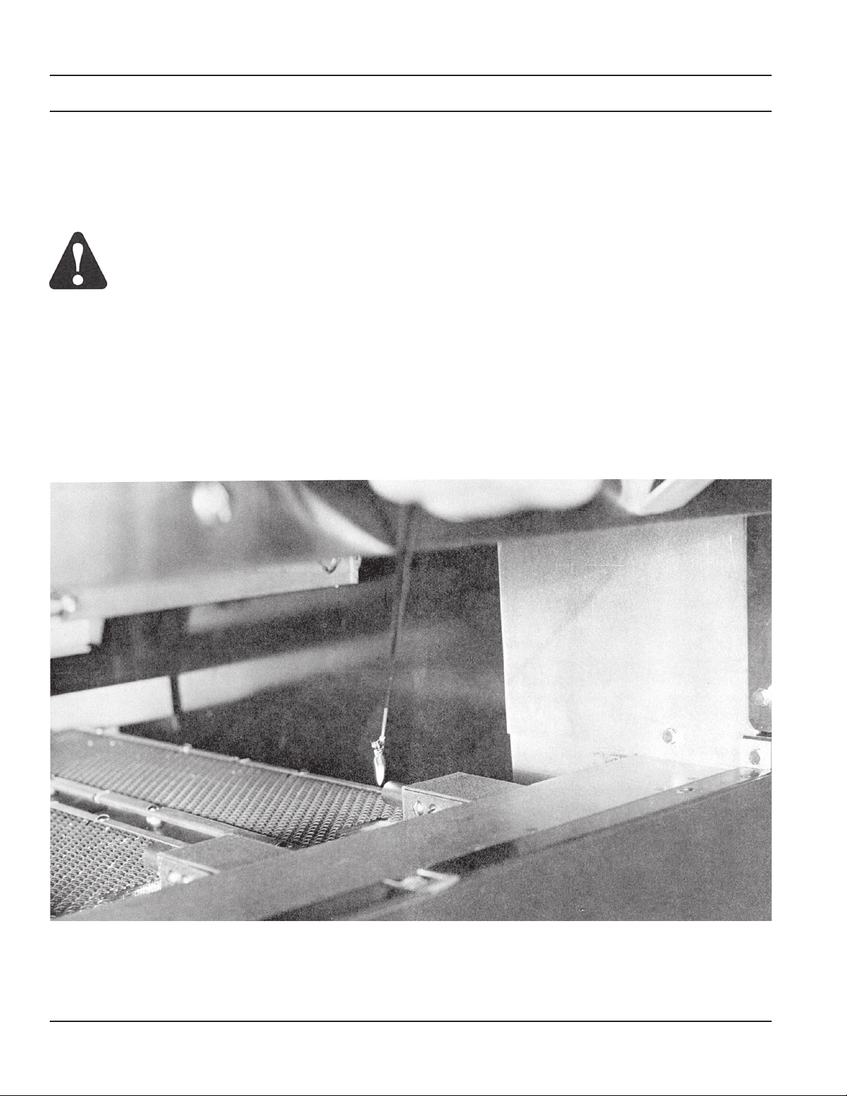
MODEL NUMBERS IR1, IR2, IR44 (INFRARED)
LIGHTING INSTRUCTIONS (SEE DETAIL B)
1. Remove the burner box cover.
2. Turn on the gas supply and check for leaks using a
soap and water solution or other acceptable method.
WARNING: MATCHES, CANDLES OR
OTHER SOURCES OF IGNITION SHOULD
NOT BE USED FOR THIS PURPOSE.
3. Turn the pilot burner “B” valve (located in the lower left
hand compartment) “on” and light pilots (one pilot per
burner) with a taper.
4. If the pilots go out, turn “off” the “B” valve and wait
5 minutes to allow gas to dissipate. Then repeat step 3.
PLACING THE UNIT INTO OPERATION
1. Flip the toggle switch located on the lower front center
panel to the “on” position.
2. Turn the burner valve to the desired setting.
SHUTDOWN INSTRUCTIONS
NIGHTLY
1. Turn the burner valve “off”.
2. Flip the toggle switch to the “off” position.
SEASONAL
1. Perform steps 1 and 2 of the nightly shutdown instructions, then turn the pilot “B” valve “off”.
DETAIL B
– 6 –
Page 7
MODEL NO.’S IR1, IR2, IR44 (INFRARED) (CONT’D)
SERVICE & PARTS GAS BROILERS
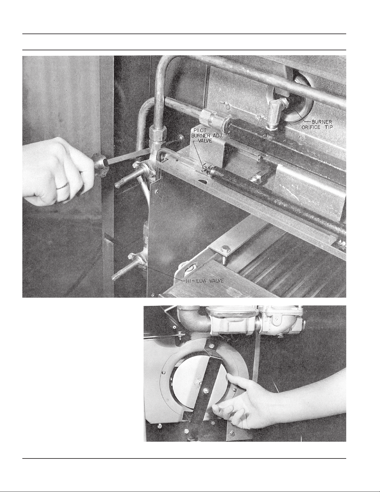
PILOT BURNER ADJUSTMENT
Turn the pilot burner “B” valve on. The valve is located in
lower compartment.
Each burner is provided with a standing pilot burner. Adjust
the pilot flame to approximately a 3⁄4" flame length. The
adjusting valve is installed in the inlet of the pilot burner
manifolding located behind the removable front panel
above the grid area.
(See Detail C & D)
MAIN BURNER ADJUSTMENT
Orifices (1 per burner) are located in the front of each
burner venturi, behind a removable front panel above the
grid area. Each burner is controlled by either a “Hi-Lo”
valve (IR1 & IR2), or a “Hi-Med-Lo” (IR44) and an orifice.
(See Detail D)
MAIN BURNER VALVE ADJUSTMENT
The “high” position is fixed and cannot be adjusted. The
“low” position may be adjusted to obtain the minimum
stable flame. In order to adjust the “low” setting, turn the
knob to low, remove the knob and rotate the adjusting
screw, located in the center shaft of the valve, clockwise to
decrease and counterclockwise to increase the burner
flame.
(See Detail D)
OPERATING
Check the unit to be sure standing pilots, one per burner,
are burning. Turn the toggle switch to the “on” position and
wait for the red indicating light to come on, then turn the
valve “on” for the desired burner and heat. (See Detail C)
CARBON ACCUMULATION ON BURNER SCREEN
If the burner screens take on a black sooty accumulation,
the burners are receiving an insufficient amount of air.
Increase the air supply at blower inlet. Carbon will burn off
as soon as proper adjustment is made.
CLEANING AND LUBRICATION
Dust and lint should be cleaned from the blower fan blades
periodically to maintain the greatest air flow and to prevent
carboning the burners.
The blower motor should be lubricated periodically using
an oil recommended by the motor manufacturer.
AIR ADJUSTMENT
Although air adjustment is made at the factory before the
unit is shipped, it may be necessary to re-adjust after
installation is made. All of the air required for combustion
is supplied by the blower through an air duct on the left
side. A single air adjustment is provided at the air intake to
the blower (IR44) or behind each “right” burner valve (IR1
& IR2). No other adjustment is provided or necessary.
(See Detail D & E)
Burners or infrared generators should burn with uniform
radiant heat and without any flame curling around the
sides of the burner.
Decrease the air supply to eliminate darkened areas.
NOTE: Insufficient air may keep the pressure switch
opened and the solenoid valve will not open to supply gas
to the unit. Increase the air supply to obtain proper operation. (IR44 only).
DETAIL C
– 7 –
Page 8
GAS BROILERS SERVICE & PARTS
MODEL NO.’S IR1, IR2, IR44 (INFRARED) (Cont’d)
DETAIL D
DETAIL E
– 8 –
Page 9

SERVICE & PARTS GAS BROILERS
TROUBLE SHOOTING THE HCB040 OVEN
PROBLEM POSSIBLE CAUSE
OVEN
TOO MUCH BOTTOM HEAT INSUFFICIENT HEAT INPUT
OVER ACTIVE FLUE
UNEVEN BAKE TEMPERATURE TOO LOW
IMPROPER OPERATION
SIDE BURNING IMPROPER BY-PASS SETTING
FLUCTUATING GAS PRESSURE
TOO MUCH TOP HEAT TEMPERATURE TOO HIGH
FAULTY VENTILATION
EXCESSIVE HEAT INPUT
THERMOSTAT NEEDS CALIBRATION
UNEVEN BAKE-SIDE TO SIDE APPLIANCE NOT LEVEL SIDE TO SIDE
OVEN BURNER, BOTTOM OR BAFFLES
IMPROPERLY INSTALLED
PULLING TO EDGE OF FAN WARPED PANS
OVEN NOT LEVEL
DOOR NOT CLOSING PROPERLY
UNEVEN BAKE-FRONT TO REAR OVER ACTIVE FLUE
UNIT NOT LEVEL, FRONT TO BACK
DRIED OUT PRODUCTS TEMPERATURE TOO LOW
BAKING TIME TOO LONG
THERMOSTAT CALIBRATION
PILOT OUTAGE PILOT FLAME TOO LOW
RESTRICTION IN PILOT ORIFICE
MALFUNCTIONING SAFETY VALVE THAT
OPERATES IN CASE OF PILOT OUTAGE
EXCESSIVE MEAT SHRINKAGE ROASTING TEMPERATURE TOO HIGH
TOP BURNER OPERATION
IMPROPER BURNER COMBUSTION
IMPROPER VENTILATION
EXCESSIVE VALVE HANDLE TEMPERATURE POOR DOOR FIT
OVEN DOOR LEFT OPEN
STICKING TOP BURNER VALVES
POOR IGNITION INSUFFICIENT INPUT
POOR AIR TO GAS ADJUSTMENT
RESTRICTION IN PILOT ORIFICE
RESTRICTION IN MAIN BURNER IGNITION
PORT RESTRICTION IN CONTROL VALVE
RESTRICTION IN GAS ORIFICE
– 9 –
Page 10

GAS BROILERS SERVICE & PARTS
TROUBLE SHOOTING - BROILERS
PROBLEM POSSIBLE CAUSE
UNEVEN BROILING TEMPERATURE TOO LOW
SIDE BURNING IMPROPER OPERATION
FLUCTUATING GAS PRESSURE
TOO MUCH TOP HEAT TEMPERATURE TOO HIGH
FAULTY VENTILATION
EXCESSIVE HEAT INPUT
OVER-RATED (PRESSURE HIGH OR
ORIFICE TOO LARGE)
UNEVEN BROIL SIDE TO SIDE UNIT NOT LEVEL SIDE TO SIDE
BROILER BURNER OR CERAMICS
IMPROPERLY INSTALLED
UNEVEN BROIL FRONT TO BACK UNIT NOT LEVEL FRONT TO BACK
DRIED OUT PRODUCTS BROILING TIME TOO LONG
OVER-RATED (PRESSURE HIGH OR
ORIFICE TOO LARGE)
PILOT OUTAGE PILOT FLAME TOO LOW
RESTRICTION IN PILOT ORIFICE
POOR IGNITION INSUFFICIENT INPUT
POOR AIR TO GAS ADJUSTMENT
RESTRICTION IN MAIN BURNER IGNITION PORT
PILOT ADJUSTMENT IS INCORRECT
– 10 –
Page 11

REPLACEMENT PARTS ORDERING
SERVICE & PARTS GAS BROILERS
NOTE: The following information must accompany a
replacement parts order or it cannot be filled.
A. Model and Style number
B. Type of Gas
C. Appliance finish, Black or Stainless Steel
(If applicable to part being replaced)
D. Blower/Motor - Volts, amps, and Hz. When applicable.
This information can be found on the rating plate of all
units.
Parts may be ordered from the Dealer, Service Agency or
Parts Depots.
– 11 –
Page 12
GAS BROILERS SERVICE & PARTS
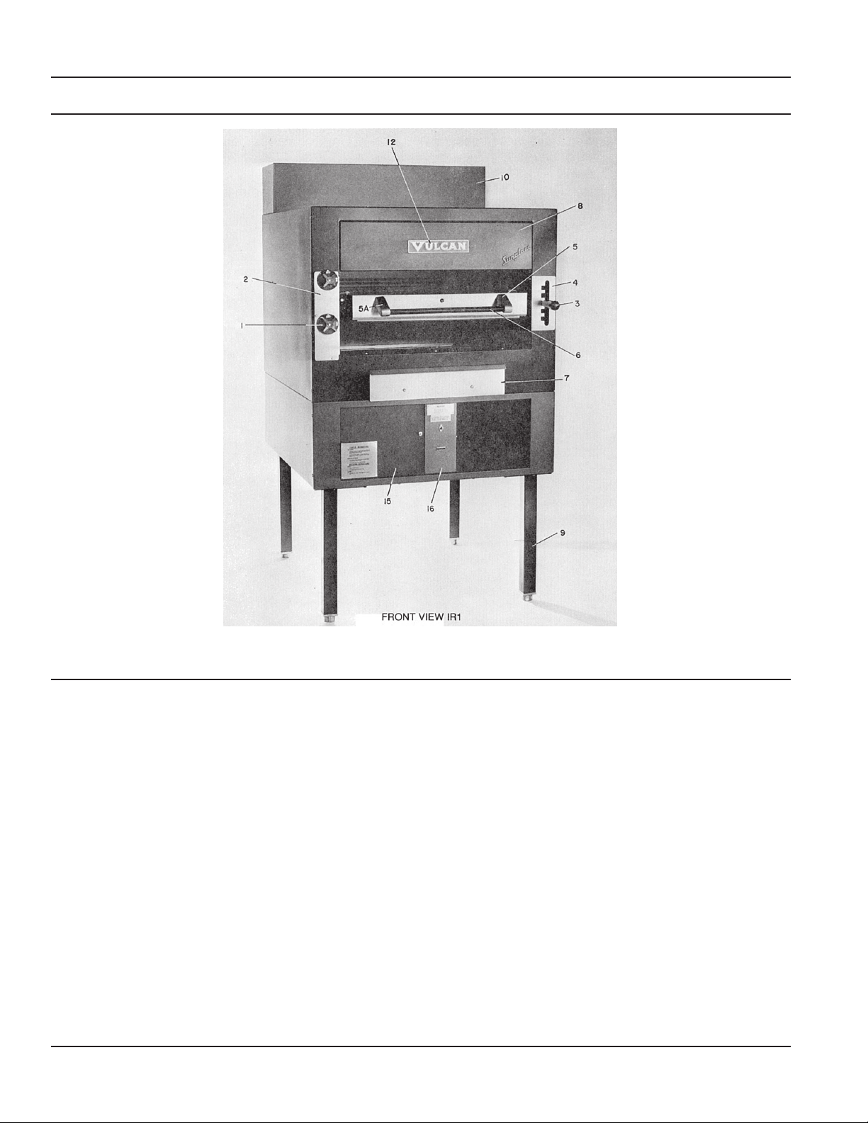
PARTS - FRONT VIEW IR1
IR1
ITEM NO. DESCRIPTION PART NO. QTY.
1 Burner Valve Knob (on-off) 107727-3 2
2 Burner Knob Cover Plate 114269-1 1
3 Grid Arm Handle 107785-2 1
4 Grid Arm Cover Index Plate 113609 1
5 Right Grid Post 104549-5 1
5A Left Grid Post 104549-6 1
6 Grid Handle 108246-1 1
7 Grease Collector Front 108161-1 1
8 Burner Shield Cover (Top) 111144-G1 1
9 Legs 113383-G1 4
9A Legs S.S. 111383-G2 4
10 Flue Riser 108218-5 1
11 Drip Tray Assembly (NS) 111040-G1 1
12 Vulcan Nameplate 105773-1 1
13 Grease Collector Assem. (NS) 107673-G1 1
14 I.D.TAB “R” 114639-1 1
14A I.D. TAB “L” 114639-2 1
15 Blower Cover Assembly 109030-G3 1
16 Lock Panel 3.0323-2 1
(NS) Not Shown
– 12 –
Page 13
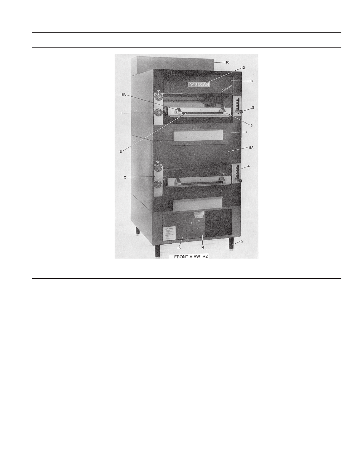
PARTS - FRONT VIEW IR2
SERVICE & PARTS GAS BROILERS
IR2
ITEM NO. DESCRIPTION PART NO. QTY.
1 Burner Knob (On-Off) 107727-3 4
2 Burner Knob Cover Plate 114269-1 2
3 Grid Arm Handle 107785-2 1
4 Grid Arm Cover Index Plate 113609-2 2
5 Right Grid Post 104549-5 1
5A Left Grid Post 104549-6 1
6 Grid Handle 108246-1 1
7 Grease Collector Front 108161-1 1
8 Burner Shield Cover (Top) 111144-G1 1
8A Burner Shield Cover (Bottom) 111144-G3 1
9 Legs 109840-1 4
9A Legs S.S. 109840-2 4
10 Flue Riser 108218-5 1
11 Drip Tray Assembly (NS) 111040-G1 1
12 Vulcan Nameplate 105773-1 1
13 Grease Collector Assembly (NS) 107673-G1 1
14 I.D. Knob Tab “R” (New style not shown) 114639-1 2
14A I.D. Knob Tab “L” (New style not shown) 114639-2 2
15 Blower Cover Assembly 109030-G3 1
16 Lock Panel 3.0323-2 1
(NS) Not Shown
– 13 –
Page 14

GAS BROILERS SERVICE & PARTS
PARTS - OLD STYLE GRID ASSEMBLY HCB040
HCB040
ITEM NO. DESCRIPTION PART NO. QTY.
1A Burner Valve Knob 102951 2
3 Grid Arm Handle (Old style shown) 107785-2 1
4 Grid Arm Cover/Index Plate 113609-2 2
5 Right Grid Post 104549-5 1
5A Left Grid Post 104549-6 1
6 Grid Handle 108246-1 1
9 (Adj.) Legs 109840-1 4
9A (Adj.) Legs (SS) 109840-2 4
12 Vulcan Nameplate 105773-1 2
19 Manifold Cover Assembly 109776-G1 1
19A Manifold Cover Assembly (SS) 109776-G2 1
20 Augratin Oven Door Assembly 105488-G1 1
20A Augratin Oven Door Assembly (SS) 105488-G2 1
21 Right Oven Door Post 104549-1 1
21A Left Oven Door Post 104549-2 1
22 Oven Door Handle 101847-1 1
23 Lower Burner Cover 105499-1 1
23A Lower Burner Cover (SS) 105499-2 1
28 Oven Handle (Lower) 109793-1 1
29 Right Door Post 109790-1 1
29A Left Door Post 109790-2 1
30 Control Panel 107699-3 1
30A Control Panel 107699-4 1
31 Valve Handle (Red) 102958 1
32 Lower Front Panel 109694-1 1
32A Lower Front Panel (SS) 109694-2 1
33 Oven Door Assembly 109791-G1 1
33A Oven Door Assembly (SS) 109791-G2 1
184 Grease Collector Front 109873-1 1
(SS) Stainless Steel
Photo shows old style grid handle assembly.
– 14 –
Page 15

PARTS - FRONT VIEW HCB 040
SERVICE & PARTS GAS BROILERS
– 15 –
Page 16

GAS BROILERS SERVICE & PARTS
PARTS - FRONT VIEW IR44
– 16 –
Page 17

SERVICE & PARTS GAS BROILERS
PARTS - FRONT VIEW IR44
IR44
ITEM NO. DESCRIPTION PART NO. QTY.
1A Burner Valve Knob Hi-Med-Lo 107727-4 2
3 Grid Arm Handle 107785-2 1
5 Right Grid Post 104549-6 1
5A Left Grid Post 104549-5 1
6 Grid Handle 107785-2 1
9 Adjustable Leg 109840-1 4
9A Adjustable Leg (SS) 109840-2 4
10 Flue Riser 114878-G1 1
11 Drip Tray Assembly (NS) 111040-G1 1
12 Vulcan Nameplate 105773-1 1
17 Left Hand Door Panel Assembly 112945-G1 1
17A Lt. Hd. Door Panel Assembly (SS) 112945-G3 1
18 Rt. Hd. Door Panel Assembly 112945-G2 1
18A Rt. Hd. Door Panel Assembly (SS) 112945-G4 1
19 Manifold Cover Assembly 109653-3 1
19A Manifold Cover Assembly (SS) 109653-4 1
20 Augratin Oven Door Assembly 105488-G1 1
20A Augratin Oven Door Assembly (SS) 105488-G2 1
21 Right Oven Door Post 104549-1 1
21A Left Oven Door Post 104549-2 1
22 Door Handle 101847-1 1
23 Burner Box Cover 105499-3 1
23A Burner Box Cover (SS) 105499-4 1
24 Pilot Light 111496-E4 1
25 Toggle Switch 21011-20 1
26 Lt. Door Panel Lining (NS) 112942-1 1
26A Lt. Door Panel Lining (NS) (SS) 112942-3 1
27 Rt. Door Panel Lining (NS) 112942-2 1
27A Rt. Door Panel Lining (NS) (SS) 112942-4 1
28 Low Profile Flue Rise (NS) 114878-1 1
28A Low Profile Flue Rise (NS) (SS) 114878-2 1
206 Cabinet Door Handle 108615-1 2
(NS) Not Shown
(SS) Stainless Steel
– 17 –
Page 18

GAS BROILERS SERVICE & PARTS
PARTS - FRONT VIEW HCB44
– 18 –
Page 19

SERVICE & PARTS GAS BROILERS
PARTS - FRONT VIEW HCB44
HCB44
ITEM NO. DESCRIPTION PART NO. QTY.
1A Burner Valve Knob 102957 2
3 Grid Arm Handle (Old style shown) 107785-2 1
4 Grid Arm Cover/Index Plate 113609-2 2
5 Right Grid Post 104549-5 1
5A Left Grid Post 104549-6 1
6 Grid Handle 108246-1 1
9 Adj. Leg 109840-1 4
9A Adj. Leg (SS) 109840-2 4
17 Door Panel Assembly, Left 112945-G1 1
17A Door Panel Assembly, Left (SS) 112945-G3 1
18 Door Panel Assembly, Right 112945-G2 1
18A Door Panel Assembly, Right (SS) 112945-G4 1
19 Manifold Cover Assembly 109776-G1 1
19A Manifold Cover Assembly (SS) 109776-G2 1
20 Augratin Oven Door Assembly 105488-G1 1
20A Augratin Oven Door Assembly 105488-G2 1
21 Right Oven Door Post 104549-1 1
21A Left Oven Door Post 104549-2 1
22 Oven Door Handle 101847-1 1
26 Left Door Liner (NS) 112942-1 1
26A Left Door Liner (NS) (SS) 112942-3 1
27 Right Door Liner (NS) 112942-2 1
27A Right Door Liner (NS) (SS) 112942-4 1
29 Lower Burner Cover 105499-1 1
29A Lower Burner Cover (SS) 105499-2 1
206 Door Handle 108615-1 2
(NS) Not Shown
(SS) Stainless Steel
Photo shows old style grid handle assembly
– 19 –
Page 20

GAS BROILERS SERVICE & PARTS
PARTS - FRONT VIEW HCB2
– 20 –
Page 21

PARTS - FRONT VIEW HCB2
SERVICE & PARTS GAS BROILERS
HCB1 HCB2
ITEM NO. DESCRIPTION PART NO. QTY. PART NO. QTY.
1 Burner Knob (On-Off) 107727-3 2 107727-3 4
2 Burner Knob Cover Plate 114269-1 1 114269-1 2
4 Grid Arm Cover Index Plate 113609-1 1 113609-1 2
5 Right Grid Handle Post 104549-5 1 104549-5 1
5A Left Grid Handle Post 104549-6 1 104549-6 1
6 Grid Handle 108246-1 1 108246-1 1
7 Grease Collector Front 108161-1 1 108161-1 2
8 Burner Shield Cover (Top) 108132-G3 1 108132-G3 1
8A Burner Shield Cover (Bottom) 108132-G5 1
9 Adj. Legs 109840-1 4 109840-1 4
9A Adj. Legs (SS) 109840-2 4 109840-2 4
10 Flue Riser 108218-5 1 108218-5 1
11 Drip Tray Assembly 111040-G1 1 111040-G1 1
12 Vulcan Nameplate 105773-1 1 105773-1 1
13 Grease Collector Assembly (NS) 107673-G1 1 107673-G1 1
14 I.D. Knob Tab “L” (Old style shown) 114639-2 1 114639-2 2
14A I.D. Knob Tab “R” (Old style shown) 114639-1 1 114639-1 2
29 Grid Arm Handle 107785-2 1 107785-2 1
(NS) Not Shown
(SS) Stainless Steel
Front View HCB1 Not Shown
– 21 –
Page 22

GAS BROILERS SERVICE & PARTS
PARTS - REAR VIEW IR1, IR2, IR44
ITEM IR1 IR2 IR44 HCB1 HCB2
NO. DESCRIPTION PART NO. QTY. PART NO. QTY. PART NO. QTY. PART NO. QTY. PART NO. QTY.
30 Body Back (Upper) 108210-3 1 108210-3 1
31 Body Back (Lower) 108210-1 1 108210-1 1 108210-1 1 108210-1 1
32 Body Back (Cabinet) 108987-G1 1 108987-G1 1 113500-F280 1 113500-F280 1
33 Inlet Pipe 113500-F280 1 113500-F280 1 113500-F2801 113500-F280 1
34 Elec. Supply Cord 105016-1 1 105016-1 1 105016-1 1 105016-1 1 105016 1
35 Elec. Cover Plate 108647-1 1 108647-1 1
36 Body Back 109896-1 1
– 22 –
Page 23

PARTS - FRONT VIEW FRAME REMOVED IR1 & IR2
SERVICE & PARTS GAS BROILERS
IR1 IR2
ITEM NO. DESCRIPTION PART NO. QTY. PART NO. QTY.
37 Air Channel Cover 115091-1 1 115091-1 2
38 Front Burner Shield Assembly 115095-G1 1 115095-G1 2
39 Fitting 1⁄2 CC to 1⁄2 MPT 3.0901-2 2 3.0901-2 4
40 Burner Sub-Manifold 114861-1 2 114861-1 4
41 Right Hand Burner Tube 115133-1 1 115133-1 2
42 Left Hand Burner Tube 115134-1 1 115134-1 2
43 Close Nipple 1⁄8" 113500-A6 4 113500-A6 8
44 Pilot Elbow Burner 105643-F 4 105643-F 8
44A Orifice Spud (Nat.) 10901-44 4 10901-44 8
44B Orifice Spud (PROPANE) 10901-55 4 10901-55 8
44C Orifice Spud (BUTANE) 10901-56 4 10901-56 8
45 Air Transition Box 115089-1 1 115089-1 1
46 Pressure Switch Tubing 109759-2 1 109759-2 1
47 Blower Motor 113552-1 1 113552-1 1
48 Solenoid 111497-F6 1 111497-F6 1
49 Regulator 108279-1 1 108279-1 1
50 Lock Panel 3.0323-2 1 3.0323-2 1
51 Toggle Switch 3.1500/ 1 3.1500/ 1
21922-20 21922-20
52 Signal Light 111496-E4 1 111496-E4 1
300 Pilot Shield (NS) 115807-1 4 115807-1 8
(NS) Not Shown
– 23 –
Page 24

GAS BROILERS SERVICE & PARTS
PARTS - FRONT VIEW FRAME REMOVED HCB2
HCB1 HCB2
ITEM NO. DESCRIPTION PART NO. QTY. PART NO. QTY.
44A Pilot Elbow Burner Nozzle (NAT.) 105643-A42 4 105643-A42 8
44B Pilot Elbow Burner Nozzle (PROPANE) 105643-F53 2 105643-F53 4
53 Elbow Street 1⁄2" x 3⁄8" 114812-1 2 114812-1 4
54 Pilot Manifold Assembly 111463-G1 1 111463-G1 2
55 Grid Arm Lifting Assembly 113607-G1 1 113607-G1 2
56 Upper Lever Arm Assembly 108870-G1 1 108870-G1 2
57 Lower Lever Arm Assembly 108774-G1 1 108774-G1 2
58 Grid Carriage Assembly 111038-G1 1 111038-G1 2
59 Roller Bearing Without Shaft (NS) 105655-1 2 105655-1 4
60 Roller Bearing With Shaft 105655-3 2 105655-3 4
61 Rt. Hd. Burner Tubing 108078-1 1 108078-1 2
62 Rt. Burner Tubing Valve to 108328-1 1 108328-1 1
Double CC Fitting
63 Lt. Burner Tubing Fitting to Valve 108329-1 1 108329-1 1
64 Burner Valve 107789-1 2 107789-1 4
65 Sub - Manifold Assembly 108076-G1 1 108076-G1 2
66 Spring Lifting Arm (Inner) 107724-1 2 107724-1 4
67 Spring Lifting Arm (Outer) 101992-2 2 101992-2 4
68 Fitting CC 3⁄8" to 1⁄2" CC 3.0131-3 2 3.0131-3 4
69 Pilot Valve 3.0130-2 2 3.0130-2 4
70 Fitting Straight 1⁄2" x 5⁄8" CC; 3.0131-2 2 3.0131-2 4
71 Fitting Straight Double 1⁄2" CC 3.0901-3 2 3.0901-3 4
72 Elbow 1⁄8" NPS x 1⁄4" CC 114800-3 1 114800-3 2
73 Pilot Tube Valve to CC Elbow 115229-1 1 115229-1 2
74 1" Manifold Pipe 108199-1 1 108199-1 2
75 Elbow Reducing 1" x 3⁄4" 114812-4 2 114812-4 4
– 24 –
Page 25

PARTS - GRID ASSEMBLY HCB2
SERVICE & PARTS GAS BROILERS
HCB1 HCB2 HCB040 HCB44
ITEM NO. DESCRIPTION PART NO. QTY. PART NO. QTY. PART NO. QTY. PART NO. QTY.
147 Grid Final Assembly 111050-G1 1 111050-G1 2 111050-G1 1 111050-G1 1
149 DripShieldRod (NS) 108111-2 1 108111-2 2 108111-2 1 108111-2 1
150 Lifting Arm Assembly (NS) 113607-G1 1 113607-G1 2 113607-G1 1 113607-G1 1
151 Burner Assembly 111551-G1 4 111551-G1 8 111551-G1 4 111551-G1 4
152 Burner Side Ceramics 104146-1 8 104146-1 16 104146-1 8 104146-1 16
153 Burner Center Ceramics 104145-1 12 104145-1 24 104145-1 12 104145-1 12
154 Lever Arm Bearing (NS) 107769-2 1 107769-2 2 107769-2 1 107769-2 1
155 Grid Stop Bolt Hex 104083-6 3 104083-6 6 104083-6 3 104083-6 3
Head 1⁄4" x 11⁄4"
156 Grid Carriage 111038-G1 1 111038-G1 2 111038-G1 1 111038-G1 1
– 25 –
Page 26

GAS BROILERS SERVICE & PARTS
PARTS - UPPER MAINFOLD ASSEMBLY HCBO40
HCB040
ITEM NO. DESCRIPTION PART NO. QTY.
69 Pilot Valve 104738-3 4
184 Grease Collector Front Panel (SS) 109873-1 1
184A Grease Collector Front Panel 109873-2 1
185 Grease Collector Assembly (SS) 109899-G2 1
185A Grease Collector Assembly 109899-G1 1
186 Pilot Orifice Spud Nat. (NS) 109125-1 4
186A Pilot Orifice Spud Mixed (NS) 109125-2 4
186B Pilot Orifice Spud Propane (NS) 109125-3 4
187 Burner Valve 108379-1 2
188 Burner Valve Tube, Rt. 108079-1 1
188A Burner Valve Tube, Lt. 108079-2 1
189 Pilot Supply Tube 111696-1 1
190 Elbow Nozzle Nat. Gas (NS) 105643-A32 4
190A Elbow Nozzle Propane Gas (NS) 105643-F53 4
190B Elbow Nozzle Butane Gas (NS) 105643-F54 4
(NS) Not Shown
(SS) Stainless Steel
– 26 –
Page 27

PARTS - IR44 WITH MANIFOLD COVER DROPPED
SERVICE & PARTS GAS BROILERS
IR44
ITEM NO. DESCRIPTION PART NO. QTY.
127 Drop Pipe 3⁄4" x 121⁄2" LG• 108425-1 1
128 Sub-Manifold 108422-G1 1
129 Valve HI-MED-LO (PROPANE) 108119-1L 2
129A Valve HI-MED-LO (NAT.) 108119-1N 2
130 Elbow 3⁄4" 90° 114798-5 1
– 27 –
Page 28

GAS BROILERS SERVICE & PARTS
PARTS - BURNER TUBING ASSEMBLY LT. & RT. IR44
IR44
ITEM NO. DESCRIPTION PART NO. QTY.
29 Grid Handle 107785-2 2
110 Burner Tubing 114863-1 2
111 Fitting 1⁄2 x 1⁄2 CC 3.0901-3 2
112 Lt. Hd. Burner Tubing 114749-1 1
113 Rt. Hd. Burner Tubing 114866-1 1
– 28 –
Page 29

PARTS - PILOT MANIFOLD ASSEMBLY IR44
SERVICE & PARTS GAS BROILERS
IR44
ITEM NO. DESCRIPTION PART NO. QTY.
44 Elbow Pilot Nozzle 105643-F 4
44A Orifice Spud (NAT.) 10901-44 4
44B Orifice Spud (PROPANE) 10901-55 4
44C Orifice Spud (BUTANE) 10901-56 4
89 Pilot Manifold Assembly 114860-1 1
135 Pilot Tube - Adj. Valve to 1/4" CC 114776-1 1
136 Burner Sub Assembly 114861-1 2
137 Front Burner Shield Assembly 114753-G1 1
138 Air Closure 114870-1 1
300 Pilot Shield (NS) 115807-1 4
(NS) Not Shown
– 29 –
Page 30

GAS BROILERS SERVICE & PARTS
PARTS - AUGRATIN OVEN COMPARTMENT IR44
IR44
ITEM NO. DESCRIPTION PART NO. QTY.
22 Handle 101847-1 1
23 Burner Box Cover 105499-3 1
139 Augratin Oven Bottom Baffle Assembly 105522-G1 1
140 Lt. Hd. Side Lining Assembly 105489-G2 1
141 Rt. Hd. Side Lining Assembly 105489-G3 1
142 Post, Left Hand 104549-2 1
143 Post, Right Hand 104549-1 1
144 Oven Door Assembly 105488-G1 1
145 Oven Rack (Augratin Oven) 104074-2 1
146 Oven Bottom Assembly (Augratin) 105123-G3 1
– 30 –
Page 31

PARTS - CONTROL PANEL
SERVICE & PARTS GAS BROILERS
IR44
ITEM NO. DESCRIPTION PART NO. QTY.
131 Control Panel 109653-5 1
132 Knob HI - MED - LO 107727-4 2
133 Signal Light 111496-E4 1
134 Toggle Switch 21022-20 1
– 31 –
Page 32

GAS BROILERS SERVICE & PARTS
PARTS - GRID ASSEMBLY HCBO40 & HCB44
HCB040 HCB44
ITEM NO. DESCRIPTION PART NO. QTY. PART NO. QTY.
147 Grid Final Assembly 111050-G1 1 111050-G1 1
148 Grid Drip Shield 111040-G1 1 111040-G1 1
149 Drip Shield Rod 111280-1 1 111280-1 1
150 Lifting Arm Assembly 1113612-G1 1 113612-G1 1
– 32 –
Page 33

SERVICE & PARTS GAS BROILERS
PARTS - AUGRATIN OVEN SECTION HCBO40 & HCB44
PARTS - AUGRATIN OVEN BAFFLE IR44, HCB44 & HCBO40
IR44 QTY. HCB040 QTY. HCB44 QTY.
ITEM NO. DESCRIPTION PART NO. PART NO. PART NO.
139 Oven Bottom Baffle Assembly 105522-G1 1 105522-G1 1 105522-G1 1
140 Oven Side Lining Assem., Lt. Hd. 105489-G2 1 105489-G2 1
140A Oven Side Lining Assem., Lt. Hd. (SS) 105489-G4 1 105489-G4 1
141 Oven Side Lining Assem., Rt. Hd. 105489-G1 1 105489-C1 1
141A Oven Side Lining Assem., Rt. Hd. 105489-G3 1 105489-G3 1
144 Augratin Oven Door Assembly 105488-G1 1 105488-G1 1
144A Augratin Oven Door Assembly (SS) 105488-G2 1 105488-G2 1
145 Oven Rack 104074-2 1 104074-2 1
146 Oven Bottom Assembly 105123-G3 1 105123-G3 1
(SS) Stainless Steel
– 33 –
Page 34

GAS BROILERS SERVICE & PARTS
PARTS - OVEN MANIFOLD & CONTROLS HCBO40
HCB040
ITEM NO. DESCRIPTION PART NO. QTY.
156 Pilot Valve 104193-1 1
157 Burner Valve 108379-1 1
158 J Hook 113091-1 2
159 Bell Crank 103956-1 2
160 Oven Door Spring 112014-2 1
161 Bell Crank Pin 103971-1 2
162 Pilot Outage Protection Valve 107798-4 1
163 Thermostat 107522-1 1
164 Filter 105922-1 1
165 Pilot Tubing Shut Off to Filter 109822-1 1
166 Pilot Tubing Filter to Tubing 109823-1 1
167 Pilot Tubing Shut Off to Pilot (NS) 113348-1 1
168 Oven Burner Tubing 109824-1 1
169 Pilot Tubing Pilot Valve to Shut Off 107846-1 1
170 Oven Door Hook, Right 105618-2 1
171 Oven Door Hook, Left 105618-1 1
172 Oven Burner Nozzle (NAT.) (NS) 3.0702-2 1
172A Oven Burner Nozzle (PROPANE) (NS) 3.0702-F 1
173 Oven Orifice Spud Propane 10901-49 1
173A Oven Orifice Spud Butane 10901-50 1
(NS) Not Shown
– 34 –
Page 35

PARTS - OVEN BAFFLE ASSEMBLY
SERVICE & PARTS GAS BROILERS
HCB040
ITEM NO. DESCRIPTION PART NO. QTY.
174 Oven Bottom Baffle 105124-5 1
175 Foil Face Insulation 105928-4 1
176 Oven Bottom Insulation Pan 109787-1 1
176A Oven Bottom Insulation Pan (SS) 109787-2 1
(SS) Stainless Steel
– 35 –
Page 36

GAS BROILERS SERVICE & PARTS
PARTS - OVEN SECTION HCBO40
HCB040
ITEM NO. DESCRIPTION PART NO. QTY.
177 Burner Assembly (Oven) 109819-G1 1
178 Upper Rt. Aeration Pan 109677-1 1
178A Upper Rt. Aeration Pan (SS) 109677-2 1
178B Upper Lt. Aeration Pan 109677-3 1
178C Upper Lt. Aeration Pan 109677-4 1
179 Lighting Hole Cover 111928-1 2
179A Lighting Hole Cover (SS) 111928-2 2
180 Oven Bottom Assembly 105123-G3 1
181 Oven Rack 104047-2 2
182 Oven Side Lining Assem., Lt. Hd. 109778-G2 1
182A Oven Side Lining Assem., Lt. Hd. (SS) 109778-G4 1
183 Oven Side Lining Assem., Rt. Hd. 109778-G1 1
183A Oven Side Lining Assem., Rt. Hd. (SS) 109778-G3 1
(SS) Stainless Steel
– 36 –
Page 37

PARTS - PILOT ASSEMBLY IR1, IR2, IR44
SERVICE & PARTS GAS BROILERS
IR1 IR2 IR44
ITEM NO. DESCRIPTION PART NO. QTY. PART NO. QTY. PART NO. QTY.
69 Pilot Adj. Valve 104738-3 1 104738-3 2 104738-3 1
89 Pilot - Sub Manifold 114860-1 1 114860-1 2 114860-1 1
90 Pilot Tube 114748-1 4 114748-1 8 114748-1 4
91 Fitting 1⁄8" MPT x 1⁄4" CC 114700-1 4 114700-1 8 114700-1 4
92 Pilot Orifice 114795-4 4 114795-4 8 114795-4 4
93 Pilot Support Housing 114862-1 4 114862-1 8 114862-1 4
94 Pilot Burner Nozzle (NAT.) 114795-1 4 114795-1 8 114795-1 4
94A Pilot Burner Nozzle (PROPANE) 114795-2 4 114795-2 8 114795-2 4
– 37 –
Page 38

GAS BROILERS SERVICE & PARTS
PARTS - MANIFOLD ASSEMBLY (TOP) IR2
ITEM NO. DESCRIPTION IR2 QTY.
PART NO.
95 Fitting 3⁄8" x 1⁄2" CC 3.0130-3 2
96A HI-LO Valve 110610-5 2
97 Manifold Pipe Assembly 108199-G2 1
102 Elbow - Reducing 3⁄4" x 1" LG. 114812-4 1
114 Elbow - Reducing 1⁄4" x 3⁄8" 114812-1 2
115 Close Nipple 1⁄4" 113500-B7 2
116 Nipple 3⁄4" x 61⁄4" LG. 113500-E50 1
117 Nipple Closed 3⁄4" 113500-E11 1
118 Union - Male Female 1" 114803-2 1
119 Elbow - Reducing 1⁄2" x 3⁄4" 114812-3 2
120 Nipple 1⁄2" x 21⁄2" LG. 113500-D20 1
121 Union 1⁄2" 114797-4 1
122 Elbow 1⁄2" 90° 114798-4 1
123 Fitting 1⁄2" x 5⁄8" CC 114700-6 2
124 Tubing 5⁄8" 109298-1 1
125 Elbow - Reducing 3⁄4" 114812-3 1
– 38 –
Page 39

SERVICE & PARTS GAS BROILERS
PARTS - MANIFOLD ASSEMBLY (BOTTOM) IR1 & IR2
IR1 IR2
ITEM NO. DESCRIPTION PART NO. QTY. PART NO. QTY.
95 Fitting 3⁄8" x 1⁄2" CC 3.0130-3 2 3.0130-3 2
96 HI-LOW Valve 110610-5 2 110610-5 2
97 Manifold Assembly 108199-G2 1 108199-G2 1
98 Union 1" Male- Female 114803-2 2 114803-2 2
99 Tee Reducing 1" x 1" x 3⁄4" 114789-1 1 114789-1 1
100 Pipe Plug 3⁄4" 114799-4
101 Nipple 1" x 12" LG. 113500-F96 1 113500-F96 1
102 Elbow Reducing 3⁄4" x 1" 114812-4 2 114812-4 2
103 “B” Valve 104949-1 1 104949-1 1
104 Pilot Tube 115156-1 1 115156-1 1
105 Solenoid 111497-F6 1 111497-F6 1
106 Regulator (PROPANE) 108279-3 1 108279-3 1
106A Regulator (NAT.) 108279-1 1 108279-1 1
107 Pipe 1" x 35" LG. 113500-F280 1 113500-F280 1
108 Nipple 3⁄4" x 1-LG. 113500-E8 3 113500-E8 3
109 Elbow Fitting 1⁄8" x 1⁄4" CC 114800-3 1 114800-3 1
NOTE: Photo shows street El Manifold Construction.
Proper construction uses (2) 3⁄4" x 1" reducing elbows 114812-4 with (2) nipples 3⁄4" x 1" 113500-E8.
Select For
[ ]
Proper Gas
– 39 –
Page 40

GAS BROILERS SERVICE & PARTS
PARTS - BLOWER MOTOR IR1 & IR2
IR1 IR2
ITEM NO. DESCRIPTION PART NO. QTY. PART NO. QTY.
47 Blower & Motor 113552-1 1 113552-1 1
48 Solenoid 111497-F6 1 111497-F6 1
49 Regulator (NAT.) 108279-1 1 108279-1 1
49A Regulator (PROPANE) 108279-3 1 108279-3 1
50 Lock Panel 3.0323-2 1 3.0323-2 1
51 Toggle Switch 3.1108 1 3.1108 1
52 Signal Light 111496-E4 1 111496-E4 1
191 Tomic Connector 3⁄8" 106774-4 4 106774-4 4
192 Conduit 10" Long 114540-B10 1 114540-B10 1
193 Pressure Switch 109254-1 1 109254-1 1
– 40 –
Page 41

PARTS - MANIFOLD CONTROLS IR44
SERVICE & PARTS GAS BROILERS
ITEM NO. DESCRIPTION IR44
PART NO. QTY.
47 Blower & Motor 113552-1 1
48 Solenoid 111497-F3 1
49 Regulator (NAT) 108279-1 1
49A Regulator (PROPANE) Select for Proper Gas 108279-2 1
130 Elbow 3⁄4" 90° 114798-5 1
193 Pressure Switch 114755-1 1
194 Air Disc 109696-G1 1
195 Disc Support 113551-1 1
196 Street El 3⁄4" 114811-2 1
197 Air Tube 114867-1 1
198 Union 3⁄4" Male - Female 114803-1 2
199 Support Angles, Left 113550-1 1
199A Support Angles, Right 113550-2 1
200 Bracket 113556-1 1
201 Riser Pipe 3⁄4" x 83⁄4" 113500-E70 1
202 Pipe 3⁄4" x 133⁄16" 113500-E106 1
204 Nipple - Closed 3⁄4" 113500-E11 1
205 Grease Pan 100994-G1 1
206 Air Duct Cover 114757-3 1
207 Air Duct (NS) 114756-1 1
208 Drop Pipe 3⁄4" x 121⁄2" 113500-E100 1
[ ]
– 41 –
Page 42

GAS BROILERS SERVICE & PARTS
PARTS - BURNER ASSEMBLY IR1 & IR2
IR1 IR2
ITEM NO. DESCRIPTION PART NO. QTY. PART NO. QTY.
76 Infrared Burner Assembly 114754-1 4 114754-1 8
– 42 –
Page 43

SERVICE & PARTS GAS BROILERS
PARTS - BURNER ASSEMBLY & CERAMICS HCB1 & HCB2
HCB1 HCB2
ITEM NO. DESCRIPTION PART NO. QTY. PART NO. QTY.
151 Burner Assembly 111551-G1 4 111551-G1 8
152 Burner Ceramic- Sides 104146-1 8 104146-2 16
153 Burner Ceramic-Center 104145-1 12 104145-1 24
– 43 –
Page 44

THIS
PAGE
INTENTIONALLY
LEFT
BLANK
 Loading...