

Page 1
INSTALLATION, SERVICE & PARTS
MANUAL FOR
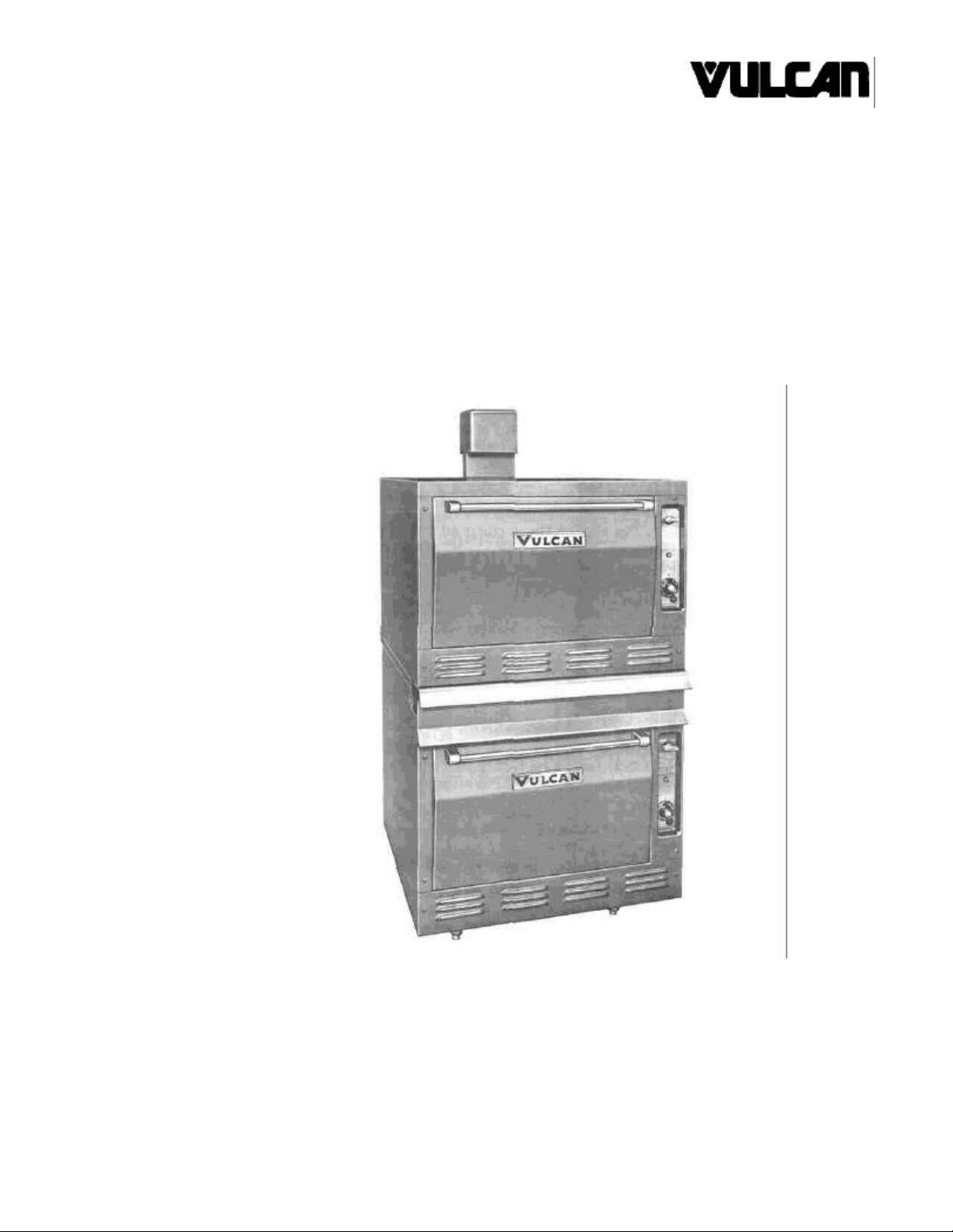
7801A, 7802A & M7801A
ROASTING OVENS
VULCAN-HART CORPORATION, 3600 NORTH POINT BOULEVARD, BALTIMORE, MARYLAND 21222
Page 2

IMPORTANT
OPERATING, INSTALLATION AND SERVICE PERSONNEL
Operating information for this equipment has been prepared for use by qualified and/or authorized
operating personnel.
All installation and service on this equipment is to be performed by qualified, certified, licensed
and/or authorized installation or service personnel, with the exception of any marked with a œ in
front of the part number.
Service may be obtained by contacting the Factory Service Department, Factory Representative
or Local Service Agency.
DEFINITIONS
QUALIFIED AND/OR AUTHORIZED OPERATING PERSONNEL
Qualified or authorized operating personnel are those who have carefully read the information in
this manual and are familiar with the equipment's functions or have had previous experience with
the operation of the equipment covered in this manual.
QUALIFIED INSTALLATION PERSONNEL
Qualified installation personnel are individuals, a firm, corporation or company which either in
person or through a representative are engaged in, and are responsible for:
1. The installation of gas piping from the outlet side of the gas meter, or the service regulator
when the meter is not provided, and the connection and installation of the gas appliance.
Qualified installation personnel must be experienced in such work, be familiar with all
precautions required, and have complied with all requirements of state or local authorities
having jurisdiction. Reference in the United States of America - National Fuel Gas code ANSI
Z223.1 (Latest Edition). In Canada-Canadian Standard CAN1-B149.1 NAT. GAS (Latest
Edition) or CAN1-B149.2 PROPANE (Latest Edition).
2. The installation of electrical wiring from the electric meter, main control box or service outlet to
the electric appliance. Qualified installation personnel must be experienced in such work, be
familiar with all precautions required, and have complied with all requirements of state or local
authorities having jurisdiction. Reference: In the United States of America-National Electrical
Code ANSI NFPA No. 70 (Latest Edition). In Canada-Canadian Electrical Code Part 1 CSAC22.1 (Latest Edition).
QUALIFIED SERVICE PERSONNEL
Qualified service personnel are those who are familiar with Vulcan equipment who have been
endorsed by the Vulcan-Hart Corporation. All authorized service personnel are required to be
equipped with a complete set of service parts manuals and stock a minimum amount of parts for
Vulcan equipment.
SHIPPING DAMAGE CLAIM PROCEDURE
For your protection, please note that equipment in this shipment was carefully inspected and
packed by skilled personnel before leaving the factory. The transportation company assumes full
responsibility for safe delivery upon acceptance of this shipment.
If shipment arrives damaged:
1. VISIBLE LOSS OR DAMAGE — Be certain this is noted on freight bill or express receipt
and signed by person making delivery.
2. FILE CLAIM FOR DAMAGES IMMEDIATELY — Regardless of extent of damage.
3. CONCEALED LOSS OR DAMAGE — If damage is unnoticed until merchandise is
unpacked, notify transportation company or carrier immediately, and file "concealed damage"
claim with them. This should be done within (15) days of date of delivery is made to you. Be
sure to retain container for inspection.
We cannot assume responsibility for damage or loss incurred in transit. We will, however, be
glad to furnish you with necessary documents to support your claim.
PLEASE RETAIN THIS MANUAL FOR FUTURE REFERENCE
Page 3
ADDENDUM GAS COOKING EQUIPMENT MANUALS
WARNING
IMPROPER INSTALLATION, ADJUSTMENT, ALTERATION
OR MODIFICATION, SERVICE OR MAINTENANCE CAN
CAUSE PROPERTY DAMAGE, INJURY OR DEATH. READ
THE INSTALLATION, OPERATING AND MAINTENANCE
INSTRUCTIONS THOROUGHLY BEFORE INSTALLING OR
SERVICING THIS EQUIPMENT.
Clearances listed in this manual apply to combustible and non-combustible materials. H Series Gas Range
clearances are now 9" at the sides and 6" at the rear.
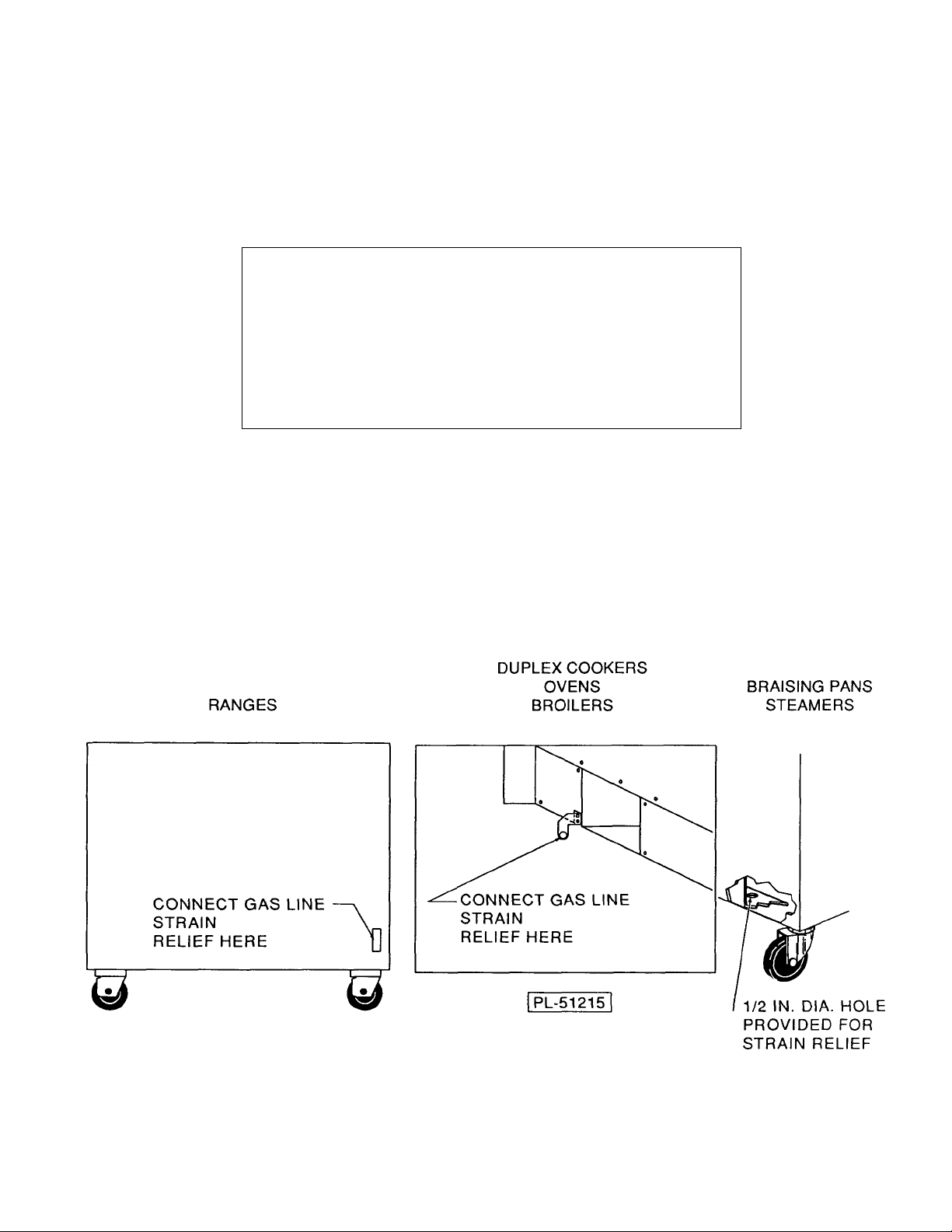
If machine is equipped with casters, the installer must provide a restraining device for the gas line to limit
movement of the equipment without depending on the connector and/or any quick-disconnect device or its
associated piping to limit movement of the equipment. Attach the restraining device to the rear of the
machine where shown below.
Page 4

IMPORTANT NOTES FOR ALL VULCAN APPLIANCES
1. These units are produced with the best possible workmanship and material. Proper installation is vital if best
performance and appearance are to be achieved. Installer must follow the installation instructions carefully.
2. Information on the construction and installation of ventilating hoods may be obtained from the "Standard for the
installation of equipment for the removal of smoke and grease laden vapors from commercial cooking equipment,"
NFPA No. 96 (latest edition) available from the National Fire Protection Association, Battery March Park, Quincy
MA 02269.
3. For an appliance equipped with a flexible electric supply cord, the cord is equipped with a three prong (grounding)
plug. This grounding plug is for your protection against shock hazard and should be plugged directly into a properly
grounded three prong receptacle. Do not cut or remove the grounding prong from this plug. If the appliance is not
equipped with a grounding plug, and electric supply is needed, ground the appliance by using the ground lug
provided (refer to the wiring diagram).
(FOR GAS APPLIANCES ONLY)
4. Do not obstruct the air flow into and around the appliance. This air flow is necessary for proper combustion of
gases and for ventilation of the appliance. Provisions for ventilation of incoming air supply for the equipment in the
room must be in accordance with National Fuel Gas Code ANSI Z223.1 (latest edition).
5. Do not obstruct the flow of flue gases from the flue duct (when so equipped) located on the rear (or sides) of the
appliance. It is recommended that the flue gases be ventilated to the outside of the building through a ventilation
system installed by qualified personnel.
6. For an appliance equipped with casters, (1) the installation shall be made with a connector that complies with the
Standard for Connectors for Movable Gas Appliances, ANSI Z21.69 (latest edition), and Addenda, Z21.69a (latest
edition), and a quick-disconnect device that complies with the Standard for Quick-Disconnect Devices for Use With
Gas Fuel, ANSI Z21.41 (latest edition), and Addenda, Z21.41 a (latest edition) and Z21.41 b (latest edition), and (2)
adequate means must be provided to limit the movement of the appliance without depending on the connector and
the quick-disconnect device or its associated piping to limit the appliance movement. If disconnection of the
restraint is necessary, reconnect this restraint after the appliance has been returned to its originally installed
position.
7. The appliance and its individual shutoff valve must be disconnected from the gas supply piping system during any
pressure testing of that system at test pressures in excess of 1/2 psig (3.45 k Pa).
8. The appliance must be isolated from the gas supply system by closing its individual manual shutoff valve during
any pressure testing of the gas supply system at test pressures equal to or less than 1/2 psig (3.45 k Pa).
CAUTIONS
FOR YOUR SAFETY
DO NOT STORE OR USE GASOLINE OR OTHER FLAMMABLE VAPORS AND LIQUIDS
IN THE VICINITY OF THIS EQUIPMENT OR ANY OTHER APPLIANCE.
1. KEEP THE APPLIANCE FREE AND CLEAR FROM ALL COMBUSTIBLE SUBSTANCES.
2. IN THE EVENT A GAS ODOR IS DETECTED, SHUT UNIT(S) DOWN AT THE MAIN
SHUTOFF VALVE AND CONTACT THE LOCAL GAS COMPANY OR GAS SUPPLIER
FOR SERVICE.
3. POST IN A PROMINENT LOCATION, INSTRUCTIONS TO BE FOLLOWED IN THE EVENT
THE SMELL OF GAS IS DETECTED. THIS INFORMATION MAY BE OBTAINED FROM A
LOCAL GAS SUPPLIER.
Page 5

7800 SERIES RANGES-INSTALLATION, SERVICE
AND PARTS MANUAL INDEX
Vulcan ranges and ovens are produced with the best possible
workmanship and material. Proper usage and maintenance will
result in many years of satisfactory performance.
DESCRIPTION PAGE
The manufacturer suggests that you thoroughly read this entire
manual and carefully follow all of the instructions provided.
DEFINITIONS OF PERSONNEL (Operating, Installation & Service)
and SHIPPING DAMAGE CLAIM PROCEDURE
CAUTIONS 1
INDEX 2
BUMPER BAR INSTALLATIONS (SG UNITS ONLY) 3
UNCRATING INSTRUCTIONS 4
UNIT INSTALLATION 4,5
(ALSO SEE INSERT SHEET A)
OVEN TEMPERATURE CONTROLS SG-7800 & 7800 6, 7
TEMPERATURE CONTROL RECALIBRATION 8,9
PILOT LIGHTING & ADJUSTMENT (ALL TOP BURNERS) 9
PILOT LIGHTING (OVEN SECTION) 10
AUTOMATIC SAFETY PILOT INSTRUCTIONS 10, 11
TROUBLE SHOOTING (PROBLEMS & CAUSES) 12
REPLACEMENT PARTS LIST 13, 14, 15
REPLACEMENT PARTS DRAWING (SEE INSERT SHEET B)
WIRING DIAGRAM—SG 18
REVISION PAGE (Inside Back Cover)
(Inside Front Cover)
The following appliances are to be installed with a six-inch clearance at the sides and rear to combustible
construction: 7860A, 7860-45A, M7860, M7860-45, M7860-72, 7860-72A, 860, M860, SG-7860A, SG-7860-72A,
SG-7860-45A, 7830A, M7830, SG-7830A, 7872A, 7872-45A, M7872-45, SG-7872A, SG-7872-45A, 872, M872,
M7872, 7801, M7801, and 7802.
The following appliances are to be installed only in non-combustible locations: 845, M845, 7845A, M7845,
7856A, SG-7856A, M7856, 7854A, SG-7854A, and M7854.
A rating plate is located on the control panel of this unit.
The rating plate states the model number, serial number
Motors in Vulcan convection ovens are permanently
lubricated and require no additional maintenance.
and type of gas unit requires.
2
Page 6
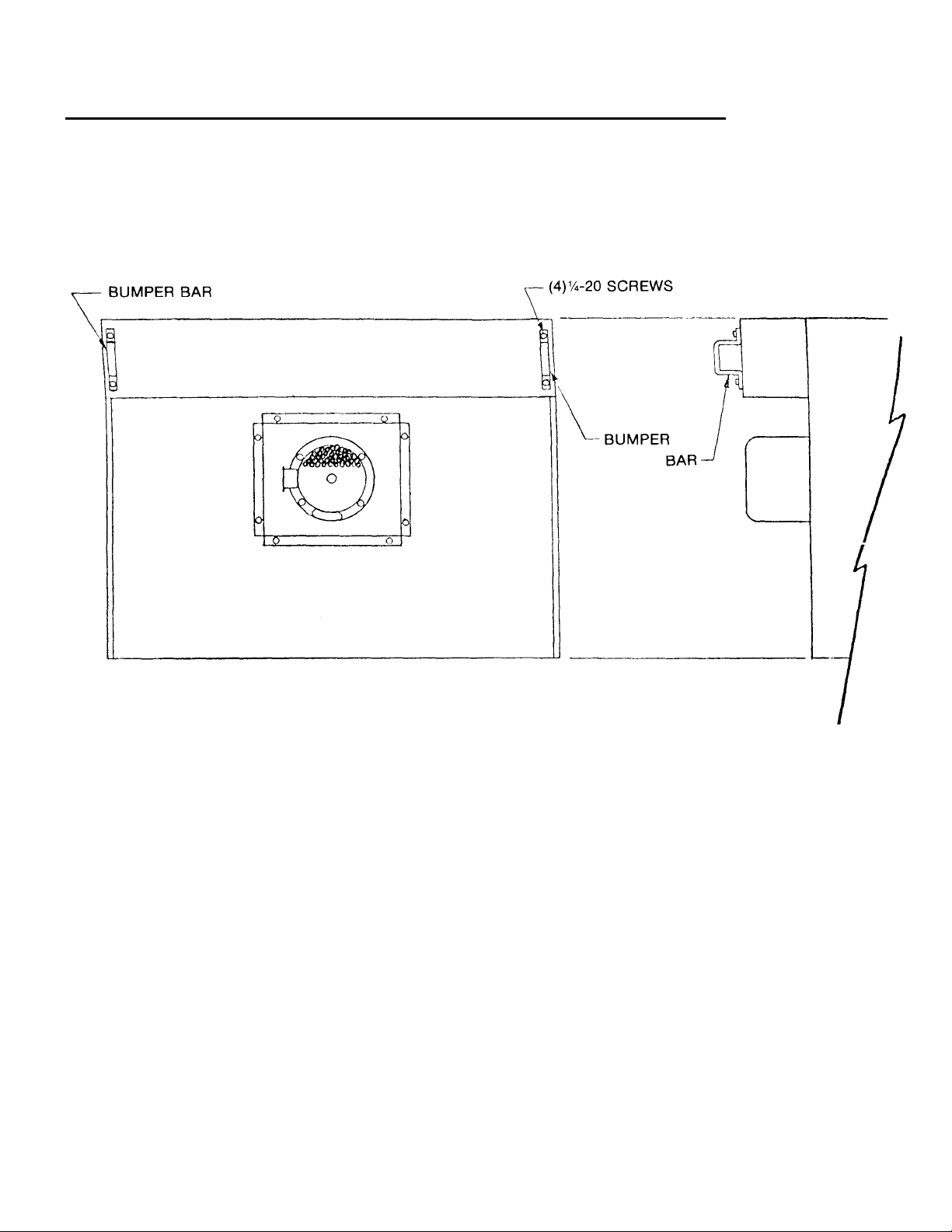
BUMPER BAR INSTALLATION 7800 SERIES UNITS
INSTALLATION PROCEDURE:
1. REMOVE EXISTING 1/4-20
SCREWS INDICATED.
2. POSITION BUMPER BARS AS SHOWN
3. REPLACE 1/4-20 SCREWS AND
SECURE BUMPER BARS AS SHOWN.
3
WARNING:
FAILURE TO INSTALL BUMPER BARS MAY
CAUSE MOTOR DAMAGE AND WILL VOID
WARRANTY.
Page 7

INSTALLATION INSTRUCTIONS FOR VULCAN 7800 SERIES
(INCLUDES ALL UNITS WITH OR WITHOUT OVENS
i.e. MODULAR & EXPANDOS.)
THE VULCAN RANGE IS PRODUCED WITH THE
BEST POSSIBLE WORKMANSHIP AND
UNCRATING INSTRUCTIONS
NOTES:
A. Pipe joint compounds used when connecting
appliances to gas should be resistant to the action of L.P.
Gases.
B. Pipe joints should be tested for leaks with a soap and
water solution before operating the unit.
C. SG 7800 Ranges are equipped with a three prong
(grounding) plug for your protection against shock hazard
and should be plugged directly into a properly grounded
three prong receptacle. Do not cut or remove the
grounding prong from this plug.
D. Snorkel Range Ovens require a minimum of 6"
clearance at the rear Snorkel Range Ovens may not be
included in a back to back set up.
1. Uncrate units carefully and place in the approximate
location they will occupy in the battery. Remove all
shipping wire and wood blocking.
2. On hot, even heat, and open top ranges, remove top
castings (A) and rear top plates (B). Identify top
castings so they are replaced in the same positions
and on same range as when received from factory.
MATERIALS. PROPER INSTALLATION IS VITAL
IF BEST PERFORMANCE AND APPEARANCE IS
T0 BE ACHIEVED. PLEASE FOLLOW THESE
INSTRUCTIONS CAREFULLY. LETTERS (A, B,
ETC.) IN THE FOLLOWING INSTRUCTIONS
REFER TO THE INSTALLATION DRAWING. SEE
INSERT A.
3. Remove oven bottom and baffles (C).
4. Remove upper manifold panel (D).
5. Removal of the shipping bracket (E) is necessary on
the corner of the range where a high shelf support
casting is to be bolted. On units equipped with a back
guard it is not necessary to remove either shipping
bracket as they will be used for support when remounting the rear top plate and back guard splasher
back (step 12).
6. Place first appliance in exact position in battery and
line up. If on "Standard " legs adjust leg heights by
turning leg feet (P) until all contact the floor. If "Less
Legs" or "On Toe Base" screw leveling bolts (F) down
until bolts contact the floor. Using carpenter level, level
up appliance from front to rear, also from side to side.
This operation is one of the most important installation
practices. No floor is level and variations of from one
to three inches in a room is common. Unless
appliances are level, difficulty will be encountered in
lining up the manifold pipe (G) and appliances will not
butt tightly.
UNIT INSTALLATION PROCEDURES
1. Move next appliance into position and level up as
explained above. Engage union nut on manifold pipe
with male fitting on next appliance and draw up union
nut hand tight. Be sure appliances butt both front and
rear. If manifolds do not line up, then ranges are not
level. Do not adjust manifold brackets (H) to make
manifolds line up, except in extreme cases, because
this will cause gas valves not to line up perfectly with
manifold cover holes. Bolt top frames together using
10-24 x 1/2" bolts (R) (Packed in cloth bag in range
oven.)
2. Continue leveling up, connecting manifold pipe and
bolting top frames of ranges together until all
appliances in battery are connected, then tighten
manifold unions gas tight. Use wrench to keep section
of union assembled to pipe from rotating. Failure to do
this may result in misalignment of valve stems.
3. Uncrate high shelves or back guards and remove
splasher backs (J).
4. Place high shelf or back guard in position and bolt
5. Bolt high shelves together by bolting through shelf
6. Replace back tops (B) and splasher backs (J).
7. If front plates (N) do not line up perfectly, adjust be
IMPORTANT NOTE:
Snorkel Range Ovens are supplied with a cord and
grounding plug assembly and must be plugged into the
proper receptacle before turning on gas.
down (high shelf) support castings (K) or (backguard)
mounting brackets (L). Bolts for mounting high shelf or
back guard are shipped in mounting holes. Just
remove and use to attach castings or brackets.
brackets (M). Bolts are in cloth bag attached to shelf.
means of bolts under front plate. Similar front
adjustment is provided for the one piece cast iron
griddle (7860A & 7860TA).
4
Page 8

UNIT INSTALLATION PROCEDURES (Cont'd.)
11. Adjust top burner pilot flames to a point where only a
trace of yellow remains, this adjustment insures the
best operating conditions.
12. The pressure regulator must be A.G.A. design
certified. Regulators must have regulation capacity for
total connected load. Regulator must have pressure
adjustment range to allow adjustment for manifold
pressure marked on unit rating plate. Unless manifold
pressure on all connected appliances is the same, a
separate regulator must be supplied for all unit(s)
having different manifold pressures.
Hi-lnput Open Top Burner & Nozzle Relationship
8. Be sure all burner and pilot valves are in a closed
position. Turn on gas supply and check for leaks. Turn on
top burner valves and allow air in line to be exhausted.
When gas begins to flow turn valves off and wait five (5)
minutes before lighting pilots.
9. Remove oven control panel (0). Control panels should be
identified and replaced on their respective units. This will
assure proper identification when repair parts are
ordered. Caution must be taken when removing the
oven control panel on a Snorkel Range.
5
Page 9

OVEN TEMP. CONTROLS 7800 SERIES
OVEN TEMPERATURE CONTROLS 7800
INSTRUCTIONS FOR ROBERTSHAW MODEL FDO
HEAVY DUTY FLAME MASTER OVEN CONTROL. This
model FDO is a precision made instrument, carefully set
at the factory to accurately control oven temperatures
from 500 degrees down to 150 degree F. All adjustments
are accessible from front of appliance after removing dial.
To remove dial, grasp knob portion and pull straight out.
BY-PASS ( MINIMUM BURNER) FLAME (Refer to figure
1) This adjustment must be made at the time the appliance is installed. To adjust this flame:
(Be sure oven burner pilot flame is ignited.)
1. With oven cold, turn dial counterclockwise slowly from "off" until main
burner gas snaps on.
2. Remove dial.
3. With a screw driver, turn "by-pass adjustment screw" counterclockwise to
increase the by-pass flame or clockwise to
decrease it until flame over entire burner is
approximately 1/8" high.
4 . Replace dial. CAUTION While making this adjustment,
if the oven should become heated while the dial is set
at a low range (below 350), the bypass flame will shut
off completely. If this occurs, turn dial counterclockwise
slowly until by-pass gas snaps on. Then check by-pass
adjustment as stated above.
OVEN TEMPERATURE CONTROLS SG-7800
1 . SG 7800 ovens are equipped with a Robertshaw KX
series snap-action thermostat. This model KX is a
precision made instrument, carefully set at the factory
to accurately control oven temperatures from 500
degrees down to 150 degrees. All adjustments are
accessible from front of appliance after removing dial.
To remove dial, grasp knob portion and pull straight
out.
2 . Replace oven control panel (check identification so
that each panel is returned to its respective unit) oven
baffles and oven bottom.
3 . Replace upper manifold panel, position brick in units
where necessary (see below) and replace top
casting, check identification so that each may be
returned to its respective original unit as received
from the factory.
4. After installing frytop adjust to control grease
drainage by adjusting leveling bolts, two (2), one (1)
each rear corner of frytop.
6
Page 10

OVEN TEMPERATURE CONTROL 7800 SERIES
THERMOSTATICALLY CONTROLLED GRIDDLE,
INSTALLATION
Set metal brick supports in place, narrow ones (1) each
side with smooth surface down and oval holes to outside,
wide ones in center with smooth surface down, triangle
shaped brick (4) set in place (2) each side as shown on
page 8. Two (2) large brick with no holes set in center
support. Four (4) large with cut out in one end and notch
on one surface set to the front and rear of each thermostat
with notch part of brick over thermostat shield bracket.
Before setting griddle in place make sure thermostat bulb
extends above end of shield (see fig. 2). Bulb is spring
loaded and should move up and down freely when
pressed with hand. This will insure good thermostat bulbto-griddle contact and accurate temperature control. When
setting griddle in place make sure that shield surrounding
bulb sets within horseshoe shaped ring on under side of
griddle. Adjust bolts (2) at rear of griddle for proper grease
drainage.
the thermostat is a slotted screw adjustment marked "B"
see figure 1. This will adjust the by-pass gas only,
counter clockwise to increase clockwise to decrease,
adjust flame to approximately 1/8" high over entire
burner.
BY-PASS FLAME ADJUSTMENT, GRIDDLE
BURNER
Make sure top pilots are lit. Turn on gas and set thermostat at 300 degrees. When griddle reaches this
temperature burner main gas supply will shut off
permitting only by-pass gas to flow. On the front of
7
Page 11

TEMPERATURE CONTROL CALIBRATION
OVEN TEMPERATURE CONTROL RECALIBRATION
Field recalibration is seldom necessary, and should not
be resorted to unless experience with cooking results,
definitely proves that the control is not maintaining the
temperature to which the dial is set. To check oven
temperatures when recalibrating use a Robertshaw Test
Instrument or a reliable mercury oven thermometer.
(Refer to figure 1 or figure 2)
FDO RECALIBRATION
1. Place the thermocouple of test instrument or
thermometer in the middle of the oven.
2. Light main burner.
3. Turn dial to 400 mark and allow oven to heat until
flame cuts down to by-pass.
4. After burner has been on sufficiently long enough to
cut down to by-pass flame, check oven temperature.
The control should be recalibrated if
your reading is not within 15 degrees of the dial
setting. If recalibration is required, proceed as follows:
5. Remove dial.
6. With a screw driver, loosen the two calibration screws
until calibration plate moves independently of the
control.
7. Turn calibration plate until mark corresponding to test
instrument or thermometer reading is in line with
center of pointer "A" and while holding in this position,
tighten calibration screws firmly.
8. Replace dial.
9. NOTE: - If the above adjustment is prevented by the
two loosened calibration screws being in contact with
the ends of the screw clearance slots in the calibration
plate, remove the screws and after turning the
calibration plate to the proper location, reassemble
screws in the other tapped holes designed for them.
8
Page 12

TEMPERATURE CONTROL RECALIBRATION (Cont'd.)
KX RECALIBRATION
1. Place the thermocouple of test instrument on the
thermostat bulb. Close oven door.
2. Light the main burner by turning thermostat to 500°
dial setting.
3. Allow the oven to heat until flame cuts off. After
several cycles, check temperature. If the temperature
does not read within 15 degrees of the dial setting,
recalibrate as follows:
4. Pull dial straight off dial shaft without turning.
5. Turn screw "A" clockwise to decrease
temperature and counterclockwise to increase
temperature.
NOTE: 1/4 turn of screw "A" represents a
temperature shift of 35°F.
PILOT LIGHTING & ADJUSTMENT (ALL TOP BURNERS)
To light range top burners, remove top section so that pilots
may be reached. Turn one burner valve "ON" to remove air
from lines. Turn burner "OFF" when gas begins to flow.
Using a taper, light top section pilots. Even though pilots
are pre-adjusted at the factory, field adjustments may be
necessary. To adjust pilots up or down, remove unit
manifold cover and using a screwdriver rotate adjusting
screw in pilot valve on manifold clockwise to decrease
flame and counterclockwise to increase flame.
9
Page 13

LIGHTING, OPERATION and SHUTTING DOWN
(OVEN SECTION)
LIGHT OVEN BURNER AS FOLLOWS:
1. OPEN MAIN GAS SUPPLY
2. TURN BURNER VALVE "ON" TO PURGE AIR FROM
LINE. TURN VALVE "OFF" WHEN GAS BEGINS TO
FLOW.
3. OPEN OVEN DOOR AND LIFT LIGHTING HOLE COVER
LOCATED ON THE LOWER FRONT COVER. WHILE
DEPRESSING SAFETY BUTTON LOCATED ON THE
UNIT OVEN CONTROL PANEL, USING A TAPER IGNITE
OVEN PILOT. CONTINUE TO HOLD SAFETY BUTTON
IN FOR APPROXIMATELY 30 SECONDS SO THAT
PILOT WILL REMAIN LIT.
4. IF PILOT DOES NOT LIGHT, TURN BURNER VALVE
"OFF", WAIT FIVE MINUTES THEN REPEAT STEPS 2
AND 3.
5. FOR SEASONAL UNIT SHUTDOWN:
A. REMOVE MANIFOLD PANEL AND TURN
OFF PILOT BURNER VALVES.
B. REMOVE OVEN CONTROL PANEL AND
CLOSE PILOT ADJUSTMENT ON SAFETY
VALVE.
C. MAKE SURE ALL BURNER VALVES AND
MAIN SUPPLY VALVES ARE OFF.
D. TO RETURN UNITS TO OPERATION
REPEAT STEPS 14 THRU 19 ON PAGES 6
AND 7.
LIGHTING, OPERATION and SHUTTING DOWN.
(OVEN SECTION SG UNITS ONLY)
LIGHT OVEN BURNER AS FOLLOWS:
1. TURN OVEN VALVE "ON".
2. IF PILOT IS OUT, TURN POWER SWITCH "OFF", WAIT 5
MINUTES BEFORE LIGHTING.
3. OPEN OVEN DOOR AND LIFT LIGHTING HOLE COVER
WHILE DEPRESSING SAFETY BUTTON, LOCATED ON
THE UNIT OVEN CONTROL PANEL USING A TAPER,
IGNITE OVEN PILOT. CONTINUE TO HOLD SAFETY
BUTTON IN FOR APPROXIMATELY 30 SECONDS SO
THAT PILOT WILL REMAIN LIT.
4. TURN POWER SWITCH A "ON"
5. SET THERMOSTAT TO DESIRED TEMPERATURE.
6. FOR COMPLETE SHUTDOWN, TURN OVEN VALVE,
POWER SWITCH AND THERMOSTAT "OFF" AND
EXTINGUISH PILOT.
AUTOMATIC SAFETY PILOT INSTRUCTIONS
CLEANING
1 . To clean pilot limiting orifice, turn "off" gas supply to
unit. Disconnect pilot tubing at the pilot burner body.
The orifice is then accessible at the body end of the
pilot burner and can be removed for cleaning. Clean
spud taking care not to enlarge the orifice hole.
SERVICE INSTRUCTIONS: (See Figure 2)
To clean valve disc and seat, turn "off"
thermostat or burner valve. Remove cap and
clean the valve disc and metal seat in the
valve body with a lint-free cloth.
2 . If valve fails to open with good pilot flame
impingement, return control to factory for
repairs.
10
Page 14

AUTOMATIC SAFETY PILOT INSTRUCTIONS
3 . Do not remove interrupter valve for field
service.
NOTE: Make certain gas line to inlet of control is
purged of air and that gas flow is available at
this point.
THERMOSTATICALLY CONTROLLED GRIDDLE,
RECLAIBRATION
Field recalibration is seldom necessary and should not be
resorted to unless cooking results definitely prove that
griddle surface temperature and thermostat setting do not
agree. To check griddle temperature use an accurate
"surface temperature thermometer" in the following
manner.
1. Locate thermometer in center of griddle
from front to rear: on 17" wide units use 1 and
center from side-to-side, on 34" wide units
use two (2) thermometers one (1) 8 1/2 " from
each side of griddle.
2. Set thermostat dial to 400 degrees and
allow griddle to heat thoroughly. When the
griddle is completely heated and the burner
is on by-pass gas check the thermometer
reading against the thermostat dial setting.
If the difference between the reading
exceeds 15 degrees the thermostat should
be recalibrated. Example: With the thermostat dial at 400 degrees and a thermometer reading of less than 385 degrees
or more than 415 degrees the thermostat
should be recalibrated.
Make note of number of degrees thermostat is off.
Remove thermostat dial and loosen calibration
screws, see drawing, until plate moves freely. Turn
calibration plate the required number of degrees
counter clockwise if the thermometer reading was
higher than the dial setting or clockwise if the
thermometer reading was lower than the dial
setting. Hold calibration plate in desired position
and tighten plate screws firmly. The number of
degrees between letters on calibration plate is 50
degrees Fahrenheit.
RECALIBRATION PROCEDURE
11
Page 15

TROUBLE SHOOTING (PROBLEMS & CAUSES)
PROBLEM PROBABLE CAUSES
OVEN
TOO MUCH BOTTOM HEAT INSUFFICIENT HEAT INPUT
UNEVEN BAKE TOO LOW TEMPERATURE
SIDE BURNING IMPROPER BY-PASS SETTING
TOO MUCH TOP HEAT TOO HIGH TEMPERATURE
UNEVEN BAKE-SIDE TO SIDE APPLIANCE NOT LEVEL SIDE TO SIDE
UNEVEN BAKE-FRONT TO REAR OVER ACTIVE FLUE
DRIED OUT PRODUCTS TOO LOW TEMPERATURE
PILOT OUTAGE PILOT FLAME TOO LOW
TOP BURNER OPERATION
IMPROPER BURNER COMBUSTION
EXCESSIVE VALVE HANDLE POOR DOOR FIT
TEMPERATURES OVEN DOOR LEFT OPEN
STICKING TOP BURNER VALVES
POOR IGNITION INSUFFICIENT INPUT
OVER ACTIVE FLUE
IMPROPER OPERATION
FLUCTUATING GAS PRESSURE
FAULTY VENTILATION
EXCESSIVE HEAT INPUT
THERMOSTAT CALIBRATION
OVEN BURNER, BOTTOM OR BAFFLES
IMPROPERLY INSTALLED
UNIT NOT LEVEL, FRONT TO BACK
DOOR NOT CLOSING PROPERLY
TOO LONG BAKING TIME
THERMOSTAT CALIBRATION
RESTRICTION IN PILOT ORIFICE
MALFUNCTIONING SAFETY VALVE
IMPROPER VENTILATION
POOR AIR-GAS ADJUSTMENT
RESTRICTION IN PILOT ORIFICE
RESTRICTION IN MAIN BURNER IGNITION PORT
12
Page 16

REPLACEMENT PARTS LIST
Part Numbers
Part Numbers
REPLACEMENT PARTS ORDERING
1 . THE FOLLOWING INFORMATION MUST ACCOMPANY A REPLACEMENT PARTS ORDER OR IT CANNOT BE
FILLED.
A. MODEL AND STYLE NUMBER
B. TYPE OF GAS.
C. APPLIANCE FINISH, PERMAFINISH, STAINLESS STEEL, ETC. (IF APPLICABLE TO PART TO
BE REPLACED.)
THIS INFORMATION CAN BE FOUND ON THE INSTRUCTION PLATE ON FRONT OF THE UNIT. PARTS
MAY BE ORDERED FROM YOUR DEALER, SERVICE AGENCY, OR THE FACTORY. ORDERS TO THE
FACTORY SHOULD BE ADDRESSED:
VULCAN-HART CORPORATION
REPAIR PARTS DEPARTMENT
3600 NORTH POINT BLVD.
BALTIMORE, MARYLAND 21222 U.S.A.
7800L SERIES RANGE REPLACEMENT PARTS LIST
ALL UNITS WITH OVENS
13
Item
1 107798-4 107798-4 Safety Valve
2 107522-1 FDO Thermostat (Oven)
111506-3 KX Thermostat (Oven N.S.
3 107789-1 Oven Valve
111497-F1 Solenoid Valve N.S.
4 109819-G2 Oven Burner
113957-1 Oven Burner N.S.
5 109125 109125 Oven Pilot Burner N.S.(See page 17)
6 112014-2 112014-2 Oven Door Spring
113091-1 113091-1 "J" Hook N.S.
113090-1 113090-1 Spring Bracket N.S.
8 105618-1 105618-1 Right Door Hook N.S.
105618-2 105618-2 Left Door Hook
9 103956-1 103956-1 Bell Crank
10 102957 102957 Plated Valve Handle
10.1 102958 Red Valve Handle
11 103981-1 103981-1 Hinge Pin One Used On
SG7800
103981-2 Hinge Pin
12 104629-2 104629-2 Hinge Pin Bearing
13 103971-1 103971-1 Bell Crank Pin
14 104074-2 Oven Rack
113991-1 Oven Rack N.S.
15 105123-G3 Oven Bottom N.S.
16 105124-5 Oven Bottom Baffle
16.1 109787 Oven Bottom Insulating Pan
17 105928-4 Oven Bottom Foil Insulation
18 109793-1 109793-1 Oven Door Handle
19 109790-1 109790-1 Right Hand Door Post
109790-2 109790-2 Left Hand Door Post
20 7940 7940 Ring 7830A, SG7830A
21 6993 6993 Lid 7830A, SG7830A
22 105817-1 105817-1 Half Cover Plate 7830A, SG7830A
23 109414-G1 109414-G1 Inner Burner 7830A, SG7830A
24 109413-01 109413-G1 Middle Burner 7830A, SG7830A
25 109412-G1 109412-G1 Outer Burner 7830A, SG7830A
26 109839 109839 Top Pilot Burner 7830A, SG7830A
27 109557-3 109557-3 Top Pilot Valve 7830A,45A,72A
60A, SG7830A
45A, 72A, 60A
7800
SG 7800
Description Remarks
Page 17

Insert B
Page 18

REPLACEMENT PARTS LIST
109557-4 109557.4 3/16 Top Pilot Valve 7856A, 54A, 53-72A
SG7856A, 54A
53-72A
104738-2 104738-2 3/16 Single Top Pilot Valve 7856A, SG7856A
28 102601 102601 Top Burner Valve 7830A, SG7830A
29 109433-1 109433-1 Top Aeration Plate 7845A, SG7845A
30 109432-1 109432-1 Top Grate 7845A, SG7845A
31 109416-1 109416-1 Burner Venturi (Lower) 7845A, SG7845A
31.1 109417-1 109417-1 Burner Head (Top) 7845A, SG7845A
32 102077-2 102077-2 Top Burner Valve 7860TA, SG7860TA
33 3.0400-4 3.0400-4 Elbow 7860TA, SG7860TA
34 108379-2 108379-2 Top Burner Valve 7845A, SG7845A
108379-1 108379-1 Top Burner Valve 7856A, SG7856A
35 104772-1 104772-1 Top Plate 7872A, SG7872A
37 110889-G40 110889-G40 Griddle Plate Assembly 7860A,7860TA
SG7860A, SG7860TA
38 105831-G3 105831-G3 Hot Top Burner 7860TA, 60A, 72A
SG7860Ta, 60A,
72A
39 104193-1 104193-1 Top Pilot Valve SG7860TA
40 108379-2 108379-2 Top Burner Valve 7860A, 72A,
SG7860A, 72A
41 109316-1 109316-1 Top Thermostat 7860TA, SG7860TA
42 110889-G36 10889-G36 17" Griddle Assembly 7860-45A, 60T-45,
SG7860-45,
60T-45A
43 105157-G2 105157-G2 Brick Set 7830A, SG7830A
44 105848-1 105848-1 Center Brick 7860A, 72A
SG7860A, 72A
44.1 105848-2 105848-2 Center Brick 7860A, SG7860A
45 106241-1 106241-1 Side Brick 7860A,72A,60TA
SG7860A, 72A, 60TA
46 109808 109808 Manifold Cover 7860A, 72A,
SG7860A, 72A
Unit And Finish Spec. Finish
47 109652 109652 Manifold Cover Must Be specified 7830A, SG7830A
When Ordering Spec. Finish
48 109692 109692 Manifold Cover 7845A, SG7845A
Spec. Finish
113856-1 113856-1 Manifold Cover 7856A, SG7856A
Spec. Fin. N.S.
49 113747-1 113747-1 Burner Tray Handle 7845A,56A
SG7845A, 56A
Spec Finish
113746-1 113746-1 Burner Tray Handle Supports N.S.
49.1 109888 109888 Burner Tray Spec. Unit & Finish
50 71732 71732 Lid Lifter 7830A, SG7830A
51 109682 109682 Grease Collector Assembly Spec. Unit & Finish
52 109778 109778 Side Lining Spec. Unit
Spec. Rt. or Lt.
53 109791 109791 Oven Door Assembly Spec. Unit & Finish
113776-G1 113776-G1 Rear Burner Assembly 7856A, SG7856A N.S.
113776-G2 113776-G2 Front Burner Assembly 7856A, SG7856 N.S.
113979-1 Oven Rack Support N.S.
114001-1 Air Director N.S.
113990-G1 Fan Cover Assembly N.S.
3.1300-7 Fan N.S.
113994-1 Motor N.S.
113866-G1 113866-G1 Top Pilot Assembly 7856A, SG7856A N.S.
113773-1 113773-1 Top Grate 7856, SG7856A N.S.
113787-1 113787-1 Nozzle Extension 7856A, SG7856A N.S.
111496-B1 On/Off Switch N.S.
111496-E4 Warning Light N.S.
105016-1 Supple Cord N.S.
14
Page 19

REPLACEMENT PARTS LIST
ORIFICE
PART No. DESCRIPTION Gas Burner
7830 VALVES
102601-44A VALVE, TOP BURNER ADJ. NAT. OUTER 44 (.086)
102601-56F VALVE, TOP BURNER FIXED L/P BUT. OUTER 55 (.052)
102601-55F VALVE, TOP BURNER FIXED L/P Prop. OUTER 54 (.050)
102601-48A VALVE, TOP BURNER ADJ. NAT. MIDDLE 48 (.076)
102601-59 F VALVE, TOP BURNER FIXED L/P. BUT. MIDDLE 58 (.042)
102601-57F VALVE, TOP BURNER FIXED L/P PROP. MIDDLE 56 (.047)
102601-53A VALVE, TOP BURNER ADJ. NAT. INNER 53 (.060)
102601-66 F VALVE, TOP BURNER FIXED L/P BUT. INNER 65 (.035)
102601-64F VALVE, TOP BURNER FIXED L/P PROP. INNER 63 (.037)
14033Y-55 NOZZLE, STRAIGHT FIXED L/P
12685-A44 NOZZLE, STRAIGHT ADJ. NAT.
104079-35A NOZZLE, TOP BURNER ADJ. NAT.
104079-53F NOZZLE, TOP BURNER FIXED L/P BUT. 1/16 (.062)
104079-52F NOZZLE, TOP BURNER FIXED L/P PROP.
3.0702-F49 NOZZLE, OVEN BURNER, FIXED L/P PROP.
3.0702-F50 NOZZLE, OVEN BURNER, FIXED L/P BUT.
3.0702-2 NOZZLE, OVEN BURNER, ADJ. NAT.
109125.1 PILOT BURNER, OVEN NAT.
109125.3 PILOT BURNER, OVEN L/P
109839-1 PILOT BURNER NAT.
109839-3 PILOT BURNER L/P
14033Y-56 NOZZLE, STRAIGHT FIXED L/P
12685-49 NOZZLE, STRAIGHT ADJ. NAT.
104079-A36 NOZZLE, OVEN BURNER ADJ. NAT.
104079-F50 NOZZLE, OVEN BURNER FIXED L/P PROP.
109125-1 PILOT BURNER, OVEN NAT.
109125-3 PILOT BURNER, OVEN L/P PROP.
7860 & 7872 NOZZLES
7845 NOZZLES
7800 OVEN NOZZLES AND PILOT BURNERS
7800 TOP PILOT BURNERS
7856A NOZZLES
SG 7800 OVEN NOZZLESAND PILOT BURNERS
Drill Size No.
7830
55 (.052)
44 (.086)
32 (.116)
51 (.067)
48 (.076)
49 (.073)
26 (.147)
77 (.018)
(.009)
77 (.018)
(.010)
56 (.046)
49 (.073)
36 (.106)
50 (.070)
77 (.018)
(.009)
15
Page 20

COOKING CHART
RECOMMENDED TEMPERATURES, TIMES AND LOADS FOR BAKING
MINUTES
NO.
OF RACKS
CONTROL
IMPORTANT
Recommended temperatures, times, number of racks and
load control settings are intended as a guide only.
Adjustments must be made to compensate for variations in
recipes, ingredients, installation and personal preference in
product appearance
RECOMMENDED TEMPERATURES,
TIMES AND LOADS FOR ROASTING
Meat roasting is most satisfactory at temperatures of 225° to
325° F. for Beef, Lamb, Poultry and Ham; 325° to 350° for
fresh Pork as recommended by USDA and American Meat
Institute
ROASTING TEMPERATURE CHART
PRODUCT
TEMPERATURE
Standing Rib Roasts—Oven Ready 250° F HI
Rolled Rib Roasts—20 to 22 Lbs 275°F HI
Veal Roast—15 Lbs 300° F HI
Turkeys—15 to 20 Lbs 300° F HI
Meal Loaf—8 to 10 Lbs 350° F HI
A pan of water (approximately 12" x 20" x 1") may be placed
in the oven bottom. This water supplies humidity to reduce
shrinkage. Water should be added if necessary during
roasting.
Roasting pans should be no deeper than necessary to hold
drippings, usually 2" to 2 1/2".
Cooking time and shrinkage may vary with roasting
temperature, cut and grade of meat and degree of doneness.
Smaller cuts will generally show greater time savings than
larger cuts at a given temperature.
LOAD
CONTROL
SETTING
APPROXIMATE TIMES
3 to 4 Hrs —Rare
4 to 4 1/2 Hrs —Med
4 Hrs.—Med
3 Hrs —Med Well
3 Hrs
45 to 60 Minutes
PRODUCT TEMPERATURE TIME IN
Cakes
Sheet Cakes 18 x 26 x 1" Pan
5
Scaled 4 1/2 to 6 Lbs Per Pan 325° to 360° F 20 to 23 4
Scaled 6 to 7 1/2 Lbs Per Pan 335° to 350° F 22 to 25 4
LOAD
Med+ to
Med to
Med to
Sheet Cakes 18 x 26 x 2" Pan 300° to 325° F 25 to 35 3 MedEquals 2-12 x 18 x 2" Pans
Scaled 10 to 12 Lbs Per 18 x 26 x 2" Pan
or 5 to 6 Lbs Per 12 x 18 x 2" Pan
Angel or Sponge Cakes
Sheet Pans 18 x 26 x 1" 300° to 325° F 15 to 20 4 Lo+
Scaled 5 to 6 Lbs Per
Loaf or Tube Pans 315° to 340°F 20 to 30 3-4 Med-to Lo
Cup Cakes 350° to 400° 6 to 12 4
Frozen Fruit Pies 350° to 375°F 30 to 45 4
3 Med-
Pumpkin or Custard Pies 300° to 350° F 30 to 45 4
Cobblers
3
Med to
Med to
Med to
Med-to
12 x 18 x 2" or 12 x 20 x 2 1/2" 350° to 400° F 30 to 45 4 Med
Meringue Pies 350° to 425° F 6 to 10 4
Fruit Turnovers 350° to 375° F 15 to 25 5
18 x 26 x 1" Pans
Cookies
Rolled or Pressed 350° to 400° F 6 to 12 5
Drop 350° to 400° F 6 to 15 5
Brownies 350° F 12 to 20 5
Rolls-1 Oz 350° to 400° F 5 to 10 4
Rolls—11/2 to 2 1/2 Ozs 350° to 400° F 8 to 15 4
3 Med-
Med to
3
2
Med to
Med to
Med to
4
3
Med to
Med- to
Med to
4
3 Lo+
Med- to
Med to
4
3 Lo+
Med-to
Med to
4
Med- to
Med to
3 Med-
Med to
3
Med- to
Loaf Bread—1 Lb. 325° to 375° F 20 to 40 3 (30 Pans) Med 2 (20 Pans) Lo+
NOTE: Pies and Cobblers; Fruit, Custard and Pumpkin Pies in tins, should be placed on 18x26x 1" Pans for
16
Page 21

COOKING CHART (Continued)
TIME IN
NO.
Yeast Bread*
RECOMMENDED TEMPERATURES, TIMES AND LOADS MISCELLANEOUS PRODUCTS
Baked Po
tatoes
RECOMMENDED TEMPERATURES, TIMES AND LOADS FOR BAKING
PRODUCT TEMPERATURE
Note: Yeast Breads should be fully proofed for best
Sweet Rolls & Danish Pastries 325° to 375° F 5 to 15 4 Med to Med 3 Med-to Lo+
Quick Breads
Biscuits 350° to 400° F 5 to 15 4 Med to MedRolled 1/2'' Thick 3 Med-to Lo+
Muffins 325° to 375° F 6 to 18 4 Med 3 Med-to Lo+
Corn Bread
5 to 7 Lbs Per Pan 335° to 400° F 10 to 20 4 Med to MedPer 18 x 26 x 1" Pan
8 to 20 Lbs Per 18 x 26 x 2" 335° to 400° F 15 to 25 4 Med to Med 3 Med-to Lo+
Corn Muffins 335° to 385° F 10 to 20 4 Med to Med 3 Med to Lo+
OVEN BROILING OR FRYING
Hamburger Patties
8 Per Lb 400° to 450° F 5 to 6 4 to 6 Hi- to Med+
Med Well Done 2 & 3 Med+ to Med
6 Per Lb 400° to 450° F 7 to 10 4 to 6 Hi to Hi 2 & 3 Hi- to Med+
4 Per Lb 375° to 450° F 8 to 12 4 to 6 Hi
2 & 3 Hi- to Med+
Fish Sticks & Portion—Frozen Breaded
1 Oz 350° to 400° F 6 to 10 4 Hi- to Med
2 & 3 Med+ to Med2 1/2 to 3 Ozs 350° to 375° F 8 to 15 4 Med+ to Med
2 & 3 Med to MedChicken Pieces—Broiler or Oven Fried
2 to2 1/2Lb Bird 375° to 425°F 8 to 15 4 to 5 Hi- to Med
2 & 3 Med+ to Med2 1/2 to 3 Lb Bird 350° to 400° F 15 to 25 4 Med+ to Med
2 & 3 Med to MedLobsters—1 to 11/2" Lb 400° to 450° 8 to 14 2 to 4 Hi to Med
Lobster Tails—Frozen
1/2 to 3/4 Lb 350° to 400° F 10 to 15 2 to 4 Hi- to Med
REHEATING PREPARED FOODS
Frozen French Fries 400° to 450° F 6 to 8 4 Hi- to Med
2 to 3 Med+ to MedFrozen Lunches (TV Dinners) 350° to 400° F 10 to12 4 to 5 Hi to Med
2 to 3 Med+ to MedFrozen Entrees (3/4" to 1" Thick) 300° to 350° F 10 to 20 2 to 5 Hi to Med
Frozen Meals (8 Oz ) Foil Pkg 350° to 400° F 20 to 30 2 to 5 Hi
CASSEROLES
Food Service Pans
2" to 3" Deep 325° to 375° F 15 to 25
3" to 4" Deep 325° to 375° F 20 to 35 2 to 4 Med+ to MedRamikins or Foil Pans 350° to 400° F 5 to 6 4 to 5 Hi to Med+
Up to 1 1/2" Deep 2 t0 4 Med+ to Med
*(Frozen 10 to 15 Minutes)
LOAD
120 Count Per 50 Lbs 400° to 450° F 20 to 25 2 to 5 Hi- to Med
100 Count Per 50 Lbs 400° to 450° F 25 to 40 2 to 5 Med+ to Med
80 Count Per 50 Lbs 400° to 425° F 30 to 50 2 to 5 Med+ to MedPizzas—Frozen or with Prebaked Crust 425° to 475° 5 to 10 4 Hi- to Med
2 & 3 Med to MedMelted Cheese Sandwiches 400° to 425° F 8 to 10 4 Hi- to Med
2 &3 Med+ to Med-
NOTES ON SPECIAL PROCEDURES FOR BAKING
Yeast Bread: Cooking starts immediately in the convection oven. Yeast Breads do not usually rise as much In the convection oven
as in a conventional oven. It is. therefore, usually necessary to allow fuller proof. 2 1/2 to 3 times Increase in volume for the best
results. Pies: When baking pies in your convection oven, 3 or 4 pies should be put on an 18 x 26" sheet or bun pan. This
procedure helps the bottom crust to bake, makes handling easier and reduces the possibility of boil over spoiling the appearance
of the pies on the lower racks.
17
Page 22

WIRING DIAGRAM—7800 SERIES
REV# DATE SIGN
1 DML
6/3/80
8/2/80
2
3 9/11/8 RWR
DML
18
 Loading...