

Page 1

VULCA
INSTALLA
399A·77R
ION.
SERVICE
MA
&
UAL
& 319A·77R
GAS
PARTS
FOR
SE
IES
OVENS
VULCAN-HART CORPORATION, 3600 NORTH
POINT
BOULEVARD, BALTIMORE,
MARYLAND
21222
Page 2

IMPORTANT
OPERATING, INSTALLING AND SERV,ICE PERSONNEL
Operating information for this equipment has been prepared for use by qualified and/or authorized
operating personnel.
All installation and service on this equipment is to be performed by qualified, certified, licensed
and/or authorized installation or service personnel, with the exception
front of the part number.
of
any marked with a 0
in
Service may
or Local Service Agency.
be
obtained by contacting the Factory Service Department, Factory Representative
DEFINITIONS
QUALIFIED ANO/OR AUTHORIZED OPERATliNG PERSONNEL
Qualified or authorized operating personnel are those who have carefuHy read the information
this manual and are familiar with the equipment's functions or have had previous experience with
the operation of the equipment covered
QUALIFIED fNST
Qualified installation personnel are individuals, a firm, corporation or company which either
person or through a representative are engaged in, and are responsible for:
1.
The installation of gas piping from the outlet side of the gas meter, or the service regulator
when the meter
Qualified installation personnel must be experienced
required, and have complied with
Reference
Canada-Canadian Standard CAN. 1-B149.1-M80 (Nat. Gas) orCAN. 1-B149.2-M80 (Propane).
ALLA
TION PERSONNEL
is
not provided, and the conneciton and installation of the gas appliance.
in
the United States
in
this manual.
in
such work,
all
requirements of state or local authorities having jurisdiction.
of
America - Nabonal Fuel Gas code ANSI Z223.1-1984.
be
familiar with all precautions
2. The installation of electrical wiring from the electric meter, main control box or service outlet to
the e'lectric appliance. Qualified installation personnel must be experienced
familiar with all precautions required, and have complied with all requirements of state or local
authorities having jurisdiction. Reference:
Code ANSI NFPA
QUALIFIED SERVICE PERSONNEL
Qualified service personnel are those who are familiar with Vulcan equipment who have been
endorsed by the Vulcan-Hart Corporation. All authorized service personnel are required to be
equipped with a complete set of service parts manua'is and stock a minimum amount of parts for
Vulcan equipment.
No.
70 1984.
In
Canada-Canadian Electricall Code Part 1 CSA-C22.1-1986.
In
the United States of America-National Electrical
in
such work, be
in
in
In
SHIPPING DAMAGE CLAIM PROCEDURE
For your protection, please note that equipment
packed by skilled personnel before leaving the factory. The transportati.on company assumes full
responsibility for safe delivery upon acceptance of this shipment.
If
shipment
1. VISIBLE LOSS
signed by person making dehvery.
2.
FILE CLAIM FOR DAMAGES IMMEDrATELY - Regardless of extent of damage.
3.
CONCEALED
notify transportation company or carrier immediately, and file "concealed damage" claim with
them. This should be done within (15) days of date of delivery is made
container for inspection.
We cannot assume responsibility for damage or loss incurred
glad to furnish you with necessary documents to support your claim.
arrives
damaged:
OR
DAMAGE -
lOSS
PLEASE RETAIN THIS
OR DAMAGE - If damage is unnoticed until merchandise
Be
certain this is noted on freight bill or express receipt and
MANUAL
in
this shipment was carefuilly inspected and
is
unpacked,
to
you. Be sure to retain
in
transit. We will, however, be
FOR FUTURE REFERENCE
Page 3
CAUTIONS
Vulcan
Plate.
(ANSI-Z223.1-1984 National Fuel Gas Code). Copies may be obtained from: The American Gas
Association,
(CAN. 1-B149.1-M80 (Nat.) or CAN. 1-B149.2-M80 (Propane) Canadian Standards.) Copies may be
obtained from: The Canadian Gas Association, 55 Scarsdale Road, Don Mills, Ontario, Canada
M3B2R3.
The
Information
"Standard
Vapors from
Fire
In
gas
The
obstruct
positioned
This
air
In
Units equipped for 120 volt
power switch off.
gas
units are
For
proper
Inc.,
following
Protection
the
event
company
areas surrounding the front, rear and sides of the unit should be kept clear so as not to
appliance is to be installed in an area with
openings
the event of a power failure, the pilots will remain lit and the unit will continue to function.
clause
on
the
for
the
Commercial
a gas odor is detected,
or
the flow of air
for easy
into the combustion
manufactured
installation
1515
construction
Installation
Association,
gas
accessibility
DO NOT attempt to operate unit until power is restored.
Wilson
pertains
supplier
necessary
only
Cooking Equipment",
Attention
Batterymarch
operation
for use with the
procedures
Blvd.,
to
units being installed in
and installation of ventilating
of
Equipment
Publication
shut
down units at main shut off valve and
for service.
for
good
for servicing.
chamber
will
in
Arlington,
for
Park, Quincy, MA
combustion
of the unit.
automatically
type
the
United
Virginia
the
Removal
NFPA
adequate
No.
Services.
and
of
gas
specified
States
22209.
the
United
hoods
96-1984
unit
air supply and
shut down. Should this happen, turn
may
of
Smoke
available from the National
02269
operation. Unit should also be
on
the
of
America
In
Canada,
States
be
obtained
and
Grease
contact
adequate
unit
Rating
refer
refer
of America.
from the
Laden
the local
clearance
to:
to:
for
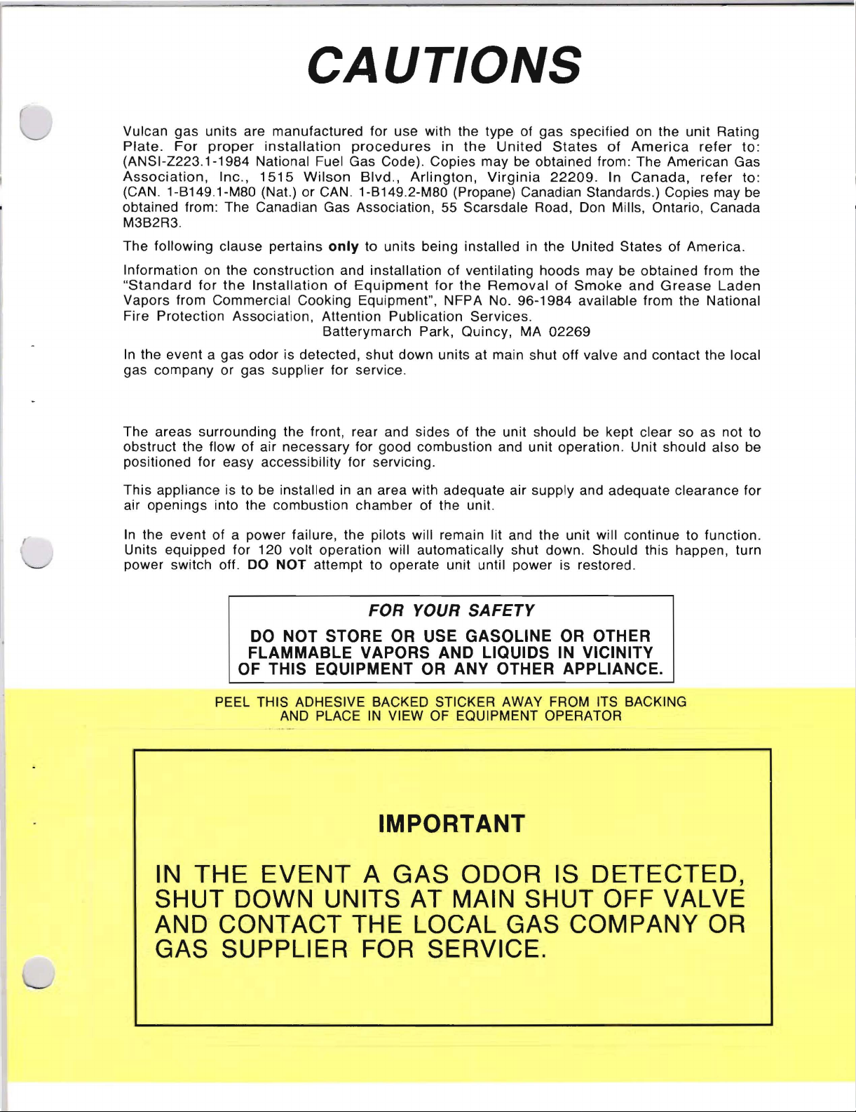
PEEL THIS ADHESIVE BACKED STICKER AWAY FROM ITS BACKING
IN
THE
SHUT
AND
GAS
FOR
YOUR
SAFETY
DO NOT STORE OR USE GASOLINE OR OTHER
FLAMMABLE VAPORS AND LIQUIDS IN VICINITY
OF THIS EQUIPMENT OR ANY OTHER APPLIANCE.
IN
AND PLACE
VIEW OF EQUIPMENT OPERATOR
IMPORTANT
EVENT
DOWN
CONTACT
SUPPLIER
A GAS
UNITS
THE
FOR
ODOR
AT MAIN
IS
SHUT
DETECTED,
OFF
LOCAL GAS COiMPANY OR
SERVICE.
VALVE
Page 4
319A-77R & 399A-77R INSTALLATION, SERVICE
AND
Vulcan Ovens are
workmanship
tenance will result in
performance.
PARTS
and material. Proper use and
MANUAL
produced
many
DESCRIPTION
DEFINITIONS
SHIPPING
CAUTION NOTES
SECTION I (INSTALLATION
CONNECTING
PILOT
SECTION
OVEN
THERMOSTAT
RECALIBRATE
OF
PERSONNEL (Operation, Installation & Service) and
DAMAGE
ADJUSTMENT
II (SERVICE
LIGHTING & SAFETY
CLAIM
UNIT
INSTRUCTIONS)
OVEN
with
the best possible
years
INSTRUCTIONS)
TO
GAS/MAIN
CONTROL
of
PROCEDURE
PILOT
main-
satisfactory
BURNER
AND
The
manufacturer
this entire manual and
instructions
suggests that you
provided.
carefully
thoroughly
follow
all
of
read
the
PAGE
(Inside Front Cover)
2
3
4
5
6
SECTION
Model
Model
A
Rating
Serial
This
construction.
III (PARTS)
319A·77R
399A·77R
Plate
Number
unit
is
to
is
and
be
is a single
is a double
located
installed
Type
on
of
with
deck
deck
the
Gas
oven.
oven.
inside
that
a 6 in.
lower
front
the
unit
clearance
control
requires.
at
the
cover.
sides
and
The
a 6 in.
Rating
clearance
Plate
states
at
the
the
rear
Model
to
Number,
combustible
7-10
Page 5
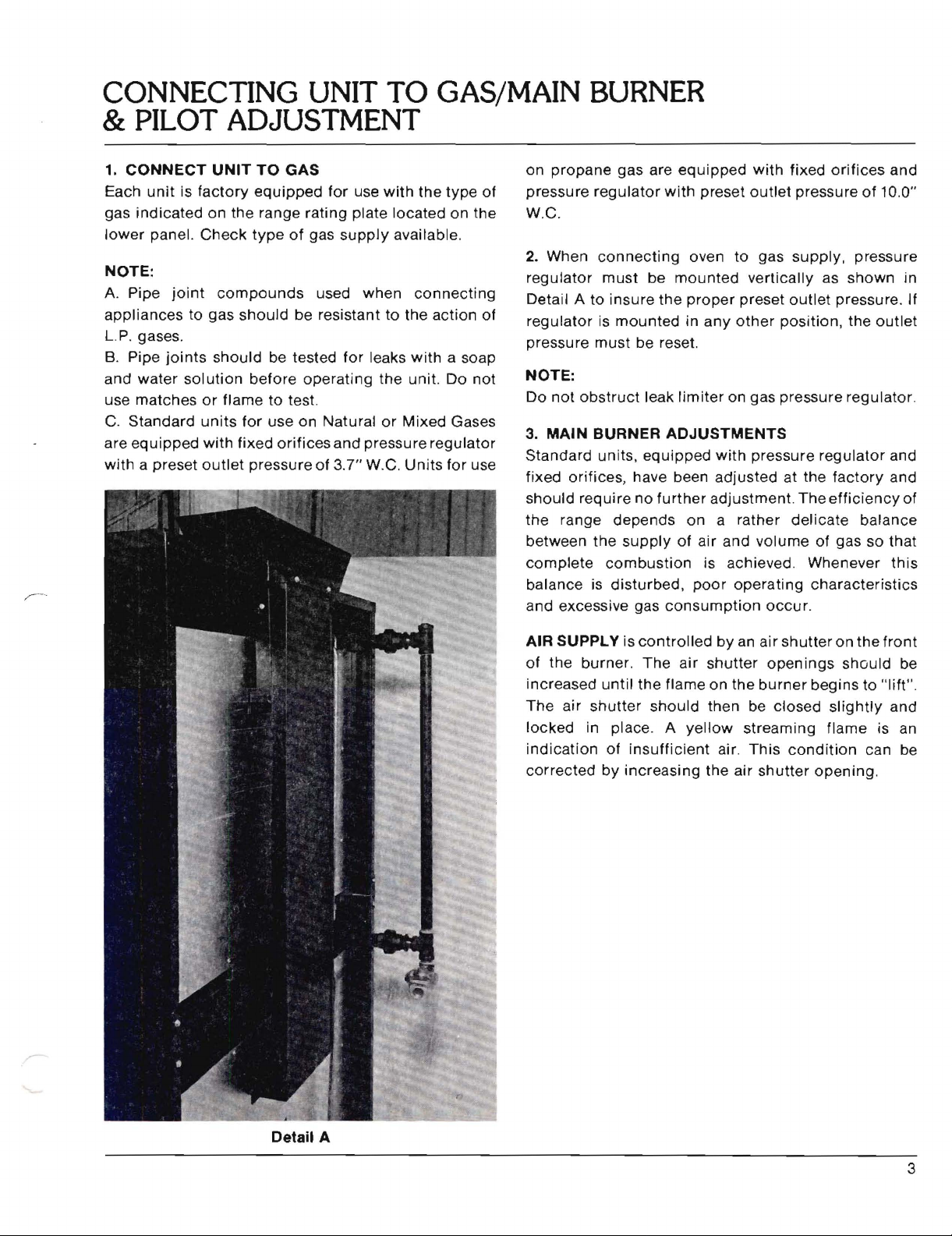
CONNECTING
UNIT
TO
& PILOT ADJUSTMENT
1.
CONNECT
Each
unit
gas
indicated
lower
panel.
NOTE:
A. Pipe
appliances
LP.
gases.
B.
Pipe
and
water
use matches
C.
Standard
are
equipped
with a preset
is
joint
to gas
joints
solution
UNIT
TO
factory
Check
or
units
with
outlet
equipped
on
the range
type
compounds
should
should
before
flame to test.
for
fixed
pressure of 3.7" W.C.
GAS
for
use
with
rating
of
be resistant to the action of
be tested
operating
use on Natural
orifices
plate located
gas
supply
used
when
for
and pressure
available.
connecting
leaks
with
the
unit. Do
or
Mixed Gases
Units
GAS/MAIN BURNER
on
the
type
on
a soap
regulator
for use
of
the
not
propane
pressure
W.C.
2.
When
regulator
Detail A
regulator
pressure
NOTE:
Do
not
3. MAIN BURNER
Standard units,
fixed orifices, have been adjusted at the
should
the
range depends on a rather
between the
complete
balance is
and excessive gas
gas are
regulator
connecting
must
to
insure
is
mounted
must
obstruct
require
supply
combustion
disturbed,
be
the
be reset.
leak
equipped
no
further
equipped
with
preset
oven to gas
mounted
proper
in
any
limiter
ADJUSTMENTS
of air and
is achieved Whenever
poor
consumption
with
fixed
outlet
supply,
vertically
preset
other
on gas pressure regulator.
with
adjustment.
operating
outlet
position,
pressure
delicate
volume
occur.
orifices
pressure
The
characteristics
of
pressure
as
shown
pressure. If
the
regulator
factory
efficiency
balance
of gas
so
outlet
and
10.0"
in
and
and
of
that
this
AIR SUPPLY is
of
the
burner.
increased
The
locked
indication
corrected
until
air
shutter
in place. A
of
by
increasing
controlled
The
air
the
flame on
should
yellow
insufficient
by
an air
shutter
the
then be
streaming
air.
This
the air
shutter
openings
burner
closed
condition
shutter
on the
should
begins to
slightly
flame
can be
opening.
front
be
"11ft".
and
is an
Detail A
3
Page 6

OVEN LIGHTING & SAFETY PILOT
NOTE:
4.
Remove
the
under
valve
pilot
burner
pilot will still
pilot. Remove
adjusting
Grayson
OVEN
LIGHTING
lower
side. Refer to Detail B. Depress red valve
each oven and
button
to
heat
off, then
screw
safety valve
panel and
depressed
the
thermocouple
wait
not
stay lit,
dust
cap above red
for
pilot
shown
& SAFETY
swing
ignite
five
pilot. See Detail C. Keep
for
one
ti
minutes
insufficient
gas. See
PILOT
lighting
minute
p.
If
hole
button
after
pilot
goes out, tu
before
Detail
relighting.
gas is reaching
button
to
C.
cover
"A"
lighting
expose
Detail B
to
rn
If
PILOT
1.
Remove
2.
Adjust
3.
Replace
GRAYSON
BURNER
pilot
pilot
key
pilot
Detail C
ADJUSTMENT:
adjustment
to
provide
adjustment
cap
properly
cap
GENERAL
B.
(Grayson)
sized flame.
B.
(Grayson)
A
B
4
Page 7

THERMOSTAT
DIAL
ASSEMBLY
01
AL
FOU~
SLEEVEHOTCHES
PILOT
AO~UITOR
"ETAL
DIAL
5.
THERMOSTAT
To
Adjust
When
dial
the
By-Pass Flame:
the
oven reaches
is
set, the oven
amount
temperature.
pass
enough
maintain
carefully
this
and
IH~
T
(Minimum
the
temperature
control
required
to
cuts
keep
Always, however,
gas
to
keep
the
entire
minimum
accurately,
flame, the by-pass
as
follows
down
the
the
burner
Burner
at
the
flow
oven at
control
must
- Detail
Flame)
which
of
gas
must
lighted.
be set
D.
Detail D
the
to
that
by-
To
IlETAINE~
TE ..PERATURE
1.
Light
2.
After
beyond
3.
Remove dial and bezel.
4.
With a screwdriver,
counterclockwise
decrease it,
over
the
5.
Replace bezel and dial,
locks
in
"AIlKS
the
oven
5 minutes,
first
mark
until
there
entire
the
burner.
"Off"
burner,
turn
on dial
to
position.
then
dial
clockwise
(Shown
turn
increase
is a
flame
turning
lolOUHTING FLANGE
turn
dial
to
to
point
by "X").
by-pass
the
flame,
clockwise
approximately
dial
clockwise
"Broil".
slightly
adjustor
Ve"
until
to
high
it
5
Page 8

RECALIBRATE OVEN CONTROL
TO RECALIBRATE OVEN
The
oven is a
calibrated
dial
settings
recalibration
resorted
cooking
maintaining
Recalibration
the by-pass
To
check
test
Place
thermometer
1.
Remove dial and push metal insert (See Detail D).
2.
Replace dial,
burner.
3.
After
oven temperature. Oven
short a time
to
see
to
results
oven
instrument
the
burner
the
precision
at
the
factory -that
match actual oven temperatures. Field
is
seldom
unless
definitely
the
temperatures
should
flame
has been adjusted.
temperatures
or
a reliable
thermocouple
in
the
middle
turn
has been on
as
possible. Use a
thermometer
CONTROL
instrument.
is, it is so adjusted
necessary, and
considerable
proves
to
not
be
undertaken,
when
mercury
of
test
of
the oven.
to
400 mark, and
about
door
should
flashlight,
reading clearly.
It is
should
experience
that
the
control
which
the dial is set.
however, until
recalibrating,
thermometer.
instrument
15
minutes
be open
if necessary,
carefully
light
that
not
be
with
is
not
use a
or
the
oven
check
for
4.
Continue
intervals, until
degrees
The
control
not
within
If
recalibration
taken are these:
5.
Hold
dial, and push
(Do
not
6.
While
screwdriver, turn dial
temperature
thermometer.
stem
...
replace dial insert.
7.
Set dial at 450 mark.
as
instructed
not
within
it means
as
control
should
to
two
of
each other.
should
10
degrees
is required, the
dial
firmly,
calibration
turn
this stem.)
holding
as
in (3) and (4).
20 degrees
that
the
be replaced.
check
shown
Release pressure on
sensing
temperature, at
successive readings are
be
recalibrated
of
the dial
insert
calibration
screwdriver
stem (See Detail C)
until
it
is set at
by
your
Check
of
oven
If
the dial
element
if
setting
additional
stem in
test
temperature
the oven
setting
is
inoperative
your
through
the
5-minute
within
reading is
(400 degrees).
steps
to
be
center
inward
firmly
actual oven
instrument
calibration
temperature
(450 degrees),
with
again,
and
or
the
5
is
6
Page 9

EXTERIOR
BODY
PARTS
4
2
__
...
--
/5
~
.~
...
,:;~
Description
1.
+
6"
Legs
+
6"
Legs (SS)
2.
3.
4.
5.
SS: Stainless Steel
+:
Specify
Model
Model
Manifold
Lower
+ Flue
+ Flue
+ Oven
+Oven Dial
No. 319A-77R is a
No. 399A-77R is a
Panel
Deflector
Deflector
Dial(Fahrenheit)
Finish
or
Cover
Assembly
Assembly
(SS)
Celcius(Optional)
Type
Single
Double
Deck Oven
Deck Oven
319A-77R
Not
3
Shown
7
Page 10

PILOT & BURNER TUBE ARRANGEMENT
319A-77R
Description 399A-77R
6.
7.
8.
9.
10.
11
13.
14.
15.
16.
NS-Not
Bell
Crank
Turnbuckle & Hooks
Oven
Door
.
Safety
Burner
Spring
Burner
Burner
Pilot
Pilot
Shown
Valve
Nozzle
Clip
Tube
Tube
Tube
Tube
Spring
Safety
Elbow
Elbow
Safety
To
To
To
Nozzle
To
Safety
Safety
Pilot
103956-1
3.0122/
12932
104053-1
105569-2
104079-F
113371-1
113370-1 113370-1
113242-1
113330-1
113328-1
319A-77R
399A~77R
103956-1
3.0122/
12932
104053-1
105569-2
104079-F
113371-1
113242-1
113330-1
113328-1
55
55
<,-)
8
Page 11

OVEN
BOTTOM
& BURNERS
SHOWING
PILOT,
THERMOCOUPLE
Descriplion
17.
+ Pilot (Nat. & Mixed)
+ Pilot (L.P. Gas)
18.
19.
20. Oven
21.
22. "V" Baffle (NS)
+:
Specify type
NS:
Thermocouple
Secondary
Oven
Not
Shown
Burner
Bottom
of
gas
Air
Pan
Assembly
(NS)
319A-77R
399A-77R 399A-77R
112787-1 112787-1
112787-2 112787-2
112788-1 112788-1
113165-1 113165-1
113225-G1 113225-G1
113234-1 113234-1
113228-1 113228-1
319A-77R
SS
SS
9
Page 12

OVEN DOOR PARTS
31
Description
6,
7,
8.
24.
25,
26.
29,
30.
31.
32. Left
33.
34.
Bell
Turnbuckle & Hooks
Oven
Bell
Hinge
Cotter
Oven
Oven
Oven
Right
Left
Right
Y;3
Crank
Door
Spring
Crank
Door
Bell
Pin
Pin
Door
Door
Door
Door
Crank
Bell
Pin
Assembly
Assembly
Handle
Handle
Handle
Hook
Crank
Hook
Post
Post
26
r
~
(Ref,)
(Ref.) (SS)
.7
2\1'
.......-
319A-77R 319A-77R
399A-77R
103956-1
3.0122/
12932
104053-1
103971-1
113201-1
10597
113267-G1
-
113257-1
113416-1
113416-2
113381-2
113381-1
a
399A-77R
103956-1
3.0122/
12932
104053-1
103971-1
113201-1
10597
113267-G2
113257-1
113416-1
113416-2
113381-2
113381-1
6
55
55
'-....--"
/
Ref: Reference
SS: Stainless Steel
10
Number
for
Complete
Assembly
Page 13
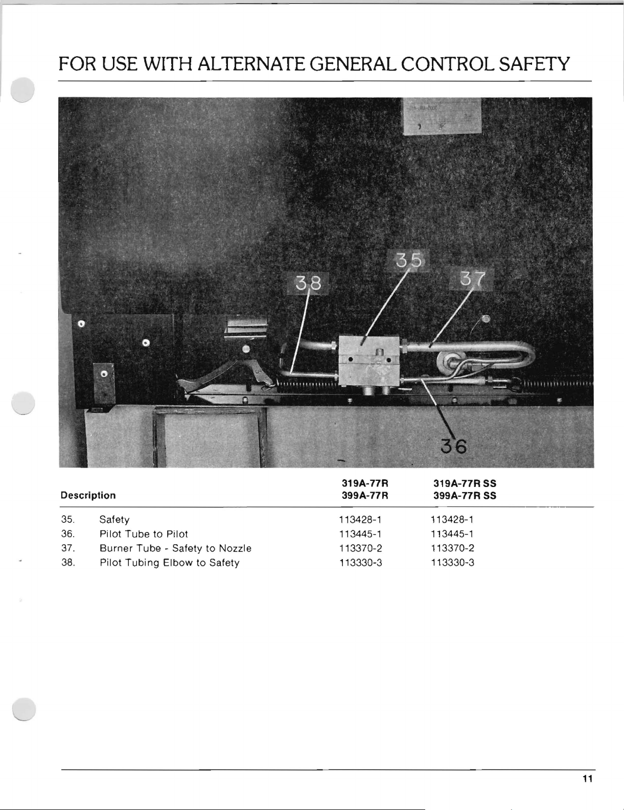
FOR USE
WITH
ALTERNATE GENERAL
CONTROL
SAFETY
319A-77R
Description 399A-77R
35.
36.
37.
38.
Safety
Pilot
Tube
Burner
Pilot
TUbing
to
Tube·
Pilot
Safety
Elbow
to Nozzle
to
Safety
113428-1
113445-1
113370-2
113330-3
319A-77R SS
399A-77R SS
113428-1
113445-1
113370-2
113330-3
11
Page 14

MANU'AL
PA:RT
NO.: 113902
REV.
SUB
BLOCK
. DATE
SIGN
FOR MODELS: 319A-77R
& 399A-77R
DESCRIPTION: Installation, Service,
And Parts Manual
1
2/2/82
DML
I
 Loading...