

Page 1
INSTALLATION, SERVICE & PARTS
MANUAL FOR
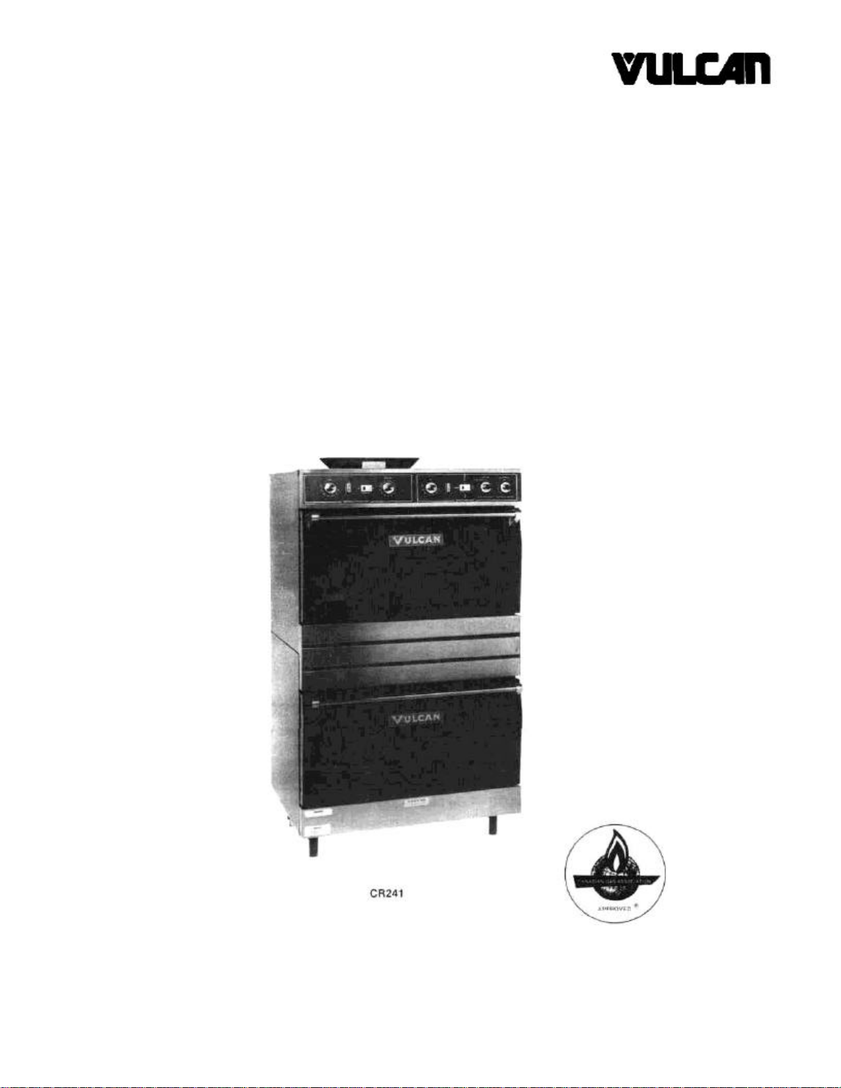
141 AND 241 SERIES
GAS OVENS
VULCAN-HART CORPORATION, 3600 NORTH POINT BOULEVARD, BALTIMORE, MARYLAND 21222,
TELEPHONE (301) 284-0660 VULCAN-HART CANADA, INC. 79 WEST STREET SOUTH, ORILLIA. ONTARIO L3V 6K5,
TELEPHONE (705) 326-6401
Page 2

IMPORTANT
OPERATING, INSTALLATION AND SERVICE PERSONNEL
Operating information for this equipment has been prepared for use by qualified and/or authorized
operating personnel.
All installation and service on this equipment is to be performed by qualified, certified, licensed
and/or authorized installation or service personnel, with the exception of any marked with a š in
front of the part number.
Service may be obtained by contacting the Factory Service Department, Factory Representative or
Local Service Agency.
DEFINITIONS
QUALIFIED AND/OR AUTHORIZED OPERATING PERSONNEL
Qualified or authorized operating personnel are those who have carefully read the information in
this manual and are familiar with the equipment's functions or have had previous experience with
the operation of the equipment covered in this manual.
QUALIFIED INSTALLATION PERSONNEL
Qualified installation personnel are individuals, a firm, corporation or company which either in
person or through a representative are engaged in, and are responsible for:
1. The installation of gas piping from the outlet side of the gas meter, or the service regulator
when the meter is not provided, and the connection and installation of the gas appliance.
Qualified installation personnel must be experienced in such work, be familiar with all
precautions required, and have complied with all requirements of state or local authorities
having jurisdiction. Reference in the United States of America - National Fuel Gas code ANSI
Z223.1 (Latest Edition). In Canada-Canadian Standard CAN1-B149.1 NAT. GAS (Latest
Edition) or CAN1-B149.2 PROPANE (Latest Edition).
2. The installation of electrical wiring from the electric meter, main control box or service outlet to
the electric appliance. Qualified installation personnel must be experienced in such work, be
familiar with all precautions required, and have complied with all requirements of state or local
authorities having jurisdiction. Reference: In the United States of America-National Electrical
Code ANSI NFPA No. 70 (Latest Edition). In Canada-Canadian Electrical Code Part 1 CSAC22.1 (Latest Edition).
QUALIFIED SERVICE PERSONNEL
Qualified service personnel are those who are familiar with Vulcan equipment who have been
endorsed by the Vulcan-Hart Corporation. All authorized service personnel are required to be
equipped with a complete set of service parts manuals and stock a minimum amount of parts for
Vulcan equipment.
SHIPPING DAMAGE CLAIM PROCEDURE
For your protection, please note that equipment in this shipment was carefully inspected and
packed by skilled personnel before leaving the factory. The transportation company assumes full
responsibility for safe delivery upon acceptance of this shipment.
If shipment arrives damaged:
1. VISIBLE LOSS OR DAMAGE — Be certain this is noted on freight bill or express receipt
and signed by person making delivery.
2. FILE CLAIM FOR DAMAGES IMMEDIATELY — Regardless of extent of damage.
3. CONCEALED LOSS OR DAMAGE — If damage is unnoticed until merchandise is
unpacked, notify transportation company or carrier immediately, and file "concealed damage"
claim with them. This should be done within (15) days of date of delivery is made to you. Be
sure to retain container for inspection.
We cannot assume responsibility for damage or loss incurred in transit. We will, however, be
glad to furnish you with necessary documents to support your claim.
PLEASE RETAIN THIS MANUAL FOR FUTURE REFERENCE
Page 3
ADDENDUM GAS COOKING EQUIPMENT MANUALS
WARNING
IMPROPER INSTALLATION, ADJUSTMENT, ALTERATION
OR MODIFICATION, SERVICE OR MAINTENANCE CAN
CAUSE PROPERTY DAMAGE, INJURY OR DEATH. READ
THE INSTALLATION, OPERATING AND MAINTENANCE
INSTRUCTIONS THOROUGHLY BEFORE INSTALLING OR
SERVICING THIS EQUIPMENT.
Clearances listed in this manual apply to combustible and non-combustible materials. H Series Gas Range clearances
are now 9" at the sides and 6" at the rear.
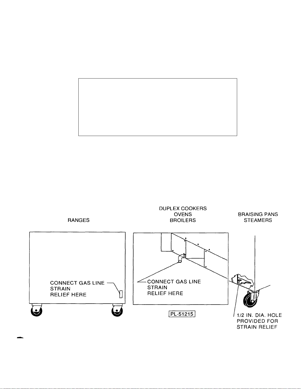
If machine is equipped with casters, the installer must provide a restraining device for the gas line to limit movement of
the equipment without depending on the connector and/or any quick-disconnect device or its associated piping to limit
movement of the equipment. Attach the restraining device to the rear of the machine where shown below.
Page 4
IMPORTANT NOTES FOR ALL VULCAN APPLIANCES
1. These units are produced with the best possible workmanship and material. Proper installation is vital if best
performance and appearance are to be achieved. Installer must follow the installation instructions carefully.
2. Information on the construction and installation of ventilating hoods may be obtained from the "Standard for the
installation of equipment for the removal of smoke and grease laden vapors from commercial cooking equipment,"
NFPA No. 96 (latest edition) available from the National Fire Protection Association, Battery March Park, Quincy
MA 02269.
3. For an appliance equipped with a flexible electric supply cord, the cord is equipped with a three prong (grounding)
plug. This grounding plug is for your protection against shock hazard and should be plugged directly into a properly
grounded three prong receptacle. Do not cut or remove the grounding prong from this plug. If the appliance is not
equipped with a grounding plug, and electric supply is needed, ground the appliance by using the ground lug
provided (refer to the wiring diagram).
(FOR GAS APPLIANCES ONLY)
4. Do not obstruct the air flow into and around the appliance. This air flow is necessary for proper combustion of
gases and for ventilation of the appliance. Provisions for ventilation of incoming air supply for the equipment in the
room must be in accordance with National Fuel Gas Code ANSI Z223.1 (latest edition).
5. Do not obstruct the flow of flue gases from the flue duct (when so equipped) located on the rear (or sides) of the
appliance. It is recommended that the flue gases be ventilated to the outside of the building through a ventilation
system installed by qualified personnel.
6. For an appliance equipped with casters, (1) the installation shall be made with a connector that complies with the
Standard for Connectors for Movable Gas Appliances, ANSI Z21.69 (latest edition), and Addenda, Z21.69a (latest
edition), and a quick-disconnect device that complies with the Standard for Quick-Disconnect Devices for Use With
Gas Fuel, ANSI Z21.41 (latest edition), and Addenda, Z21.41 a (latest edition) and Z21.41 b (latest edition), and (2)
adequate means must be provided to limit the movement of the appliance without depending on the connector and
the quick-disconnect device or its associated piping to limit the appliance movement. If disconnection of the
restraint is necessary, reconnect this restraint after the appliance has been returned to its originally installed
position.
7. The appliance and its individual shutoff valve must be disconnected from the gas supply piping system during any
pressure testing of that system at test pressures in excess of psig (3.45 k Pa).
8. The appliance must be isolated from the gas supply system by closing its individual manual shutoff valve during
any pressure testing of the gas supply system at test pressures equal to or less than 1/2 psig (3.45 k Pa).
CAUTIONS
FOR YOUR SAFETY
DO NOT STORE OR USE GASOLINE OR OTHER FLAMMABLE VAPORS AND LIQUIDS
IN THE VICINITY OF THIS EQUIPMENT OR ANY OTHER APPLIANCE.
1. KEEP THE APPLIANCE FREE AND CLEAR FROM ALL COMBUSTIBLE SUBSTANCES.
2. IN THE EVENT A GAS ODOR IS DETECTED, SHUT UNIT(S) DOWN AT THE MAIN
SHUTOFF VALVE AND CONTACT THE LOCAL GAS COMPANY OR GAS SUPPLIER
FOR SERVICE.
3. POST IN A PROMINENT LOCATION, INSTRUCTIONS TO BE FOLLOWED IN THE EVENT
THE SMELL OF GAS IS DETECTED. THIS INFORMATION MAY BE OBTAINED FROM A
LOCAL GAS SUPPLIER.
Page 5
CAUTION
Reference: ANSI/NFPA 96-1984 4-1.2.2.2. of the
National Fire Protection Association, Inc., Batterymarch
Park, Quincy, MA 02269, and National Building Code
1976
Sec. 1015.7b (2) of The American Insurance Association.
Engineering and Safety Service, 85 John Street, New York, NY
10038
4
Page 6
CAUTION NOTES (Continued)
IMPORTANT
This appliance must be installed under a ventilation hood, when equipped with a flue deflector.
WARNING — ELECTRICAL GROUNDING INSTRUCTIONS:
This appliance is equipped with a three prong (grounding) plug for your protection against shock
hazard and should be plugged directly into a properly grounded three prong receptacle. Do not cut
or remove the grounding prong from this plug.
When this appliance is connected to a direct vent, a down draft diverter must be used. Vent pipe
must be minimum of 6" diameter and should be periodically checked for obstructions to maintain
satisfactory performance.
NOTE:
All wiring diagrams are packaged separately in a clear plastic envelope resting on top of the oven
rack.
FROM THE TERMINATION OF THE APPLICANCE FLUE VENT TO THE FILTERS OF THE
HOOD VENTING SYSTEM, AN 18 INCH MINIMUM CLEARANCE MUST BE MAINTAINED.
REFERENCE: ANSI/NFPA 96—1984 4-1.2.2.2 OF THE NATIONAL FIRE PROTECTION ASSOCIATION, INC., BATTERYMARCH PARK, QUINCY, MASS. 02269. AND NATIONAL BUILDING
CODE 1976 SEC. 1015.7b (2) OF THE AMERICAN INSURANCE ASSOCIATION, ENGINEERING
AND SAFETY SERVICE, 85 JOHN STREET, NEW YORK, N.Y. 10038.
5
THIS EQUIPMENT IS DESIGN CERTIFIED BY A NATIONALLY
RECOGNIZED TESTING LABORATORY TO THE APPROPRIATE
NATIONAL STANDARDS AS INDICATED ON THE EQUIPMENT
RATING PLATE. ANY MODIFICATION WITHOUT WRITTEN
PERMISSION OF VULCAN-HART CORPORATION VOIDS THE
CERTIFICATION AND WARRANTY OF THIS UNIT.
Page 7

141 &241 SERIES OVEN
INSTALLATION, SERVICE & PARTS MANUAL INDEX
Your Vulcan Oven is produced with the best possible
workmanship and material. Proper usage and
maintenance will result in many years of satisfactory
performance.
DESCRIPTION PAGE
The manufacturer suggests that you thoroughly read this
entire manual and carefully follow all of the instructions
provided.
DEFINITIONS OF PERSONNEL (Operating, Installation and Service)
and SHIPPING DAMAGE CLAIM PROCEDURE
CAUTION NOTES 4-5
INDEX 6
BUMPER BAR INSTALLATION INSTRUCTION SHEET 7
SECTION I (INSTALLATION INSTRUCTIONS)
CONNECTING OVEN TO GAS/MAIN BURNER ADJUSTMENT 8
SECTION II (SERVICE INSTRUCTIONS)
OVEN LIGHTING 9
SERVICE REPLACEMENT 10-14
BURNER ORIFICE DATA & PILOT ADJUSTMENT 13
SECTION III
REPLACEMENT PARTS 15-24
REVISION PAGE (Inside Back Cover)
(Inside Front Cover)
Model 141 is a single deck oven.
Model 241 is a double deck oven.
The rating plate is located on the inside of the
lower front panel. The rating plate states the model
number, serial number, and type of gas that the
unit requires.
The following is a description of model number prefix:
C = Convection Snorkel™ Oven
S = Standard Oven
This unit is to be installed with a 6 inch clearance
at the sides and a 6 inch clearance at the rear
adjacent to combustible construction.
R = Roast & Hold in Standard Oven
Z = Convection Snorkel™ Oven with "Roast and Hold"
6
Page 8
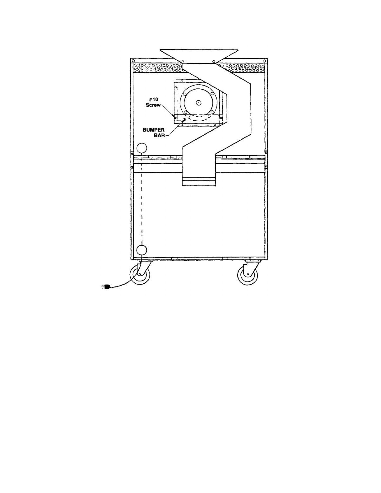
INSTALLATION PROCEDURE: 1 REMOVE EXISTING #10 SCREWS INDICATED.
2 POSITION BUMPER BAR AS SHOWN.
3 REPLACE #10 SCREWS AND SECURE BUMPER BAR.
WARNING FAILURE TO INSTALL BUMPER BAR MAY CAUSE MOTOR DAMAGE
AND WILL VOID WARRANTY.
141 OR 241 UNIT BUMPER BAR INSTALLATION INSTRUCTIONS
7
Page 9

CONNECTING UNIT TO GAS/MAIN BURNER ADJUSTMENT
CONNECT UNIT TO GAS
1. Each unit is factory equipped for use with the type of
gas indicated on the range rating plate located on the
lower panel. Check type of gas supply available.
NOTE:
A. Pipe joint compounds used when connecting
appliances to gas should resist the action of L.P.
gases.
B. Pipe joints should be tested for leaks with a soap and
water solution before operating the unit. Do not use
matches or flame to test.
C. Standard units for use on natural or mixed gases are
equipped with fixed orifices and a pressure regulator
with a preset outlet pressure of 3.7" W.C. Units for
use on propane gas are equipped with fixed orifices
and pressure regulator with preset outlet pressure of
10.0" W.C.
2. When connecting the oven to the gas supply, the pres-
sure regulator must be mounted vertically as shown in
Detail A2 to insure the proper preset outlet pressure.
If the regulator is mounted in any other position, the
outlet pressure must be reset.
NOTE:
The unit and its individual shut-off valve must be disconnected from the gas supply piping system during any
pressure testing of that system at test pressures in
excess of 1/2 psig (3.45 L PA.) The appliance must also
be isolated
from the gas supply piping system by closing its
individual manual shut-off valves during any pressure
testing of the gas supply piping system at test pressures
equal to or less than 1/2 psig (3.45 L PA.) as stated by
the American National standards Z83.11-1986. Copies of
this standard are available from the American Gas
Association, 1515 Wilson Blvd., Arlington, VA 22209.
NOTE:
Do not obstruct the leak limiter on the gas pressure regulator.
3. MAIN BURNER ADJUSTMENT
Standard units, equipped with a pressure regulator and
fixed orifices, have been adjusted at the factory and
should require no further adjustment. The efficiency of
the oven depends on a rather delicate balance between
the supply of air and volume of gas so that complete
combustion is achieved. Whenever this balance is
disturbed, poor operating characteristics and excessive
gas consumption occur.
AIR SUPPLY is controlled by an air shutter on the front
of the burner. The air shutter openings should be increased until the flame on the burner begins to "lift". The
air shutter should then be closed slightly and locked in
place. A yellow streaming flame is an indication of insufficient air. This condition can be corrected by increasing
the air shutter opening.
8
Page 10

OVEN LIGHTING
OVEN LIGHTING
To check the oven burner pilots for standard and Snorkel
ovens, remove the lower front panel and lift up the
lighting hole cover. If the pilot is out, relight as described
below.
LIGHTING INSTRUCTIONS
1. Turn the oven and the pilot valve on.
2. If the pilot is out, turn the power switch and thermostat
"off", wait five minutes before relighting.
3. Depress the button and ignite the pilot, hold the
button in 30 seconds until the pilot remains lit.
4. Turn the power switch "on", set the temperature dial
to the desired temperature.
5. For complete shut down, turn the oven valve, pilot
valve, power switch and thermostat to "off". (Refer to
Detail E)
The above lighting instructions for the standard and
Snorkel ovens can also be found on the inside lower
front panel of each unit.
DETAIL E
9
Page 11

SERVICE REPLACEMENT
REPLACEMENT OF SOLENOID VALVE (DETAIL F)
Turn off the gas supply at the shut off valve and the pilot
valve.
Break the compression fitting at the pilot outage protection
device and solenoid valves.
Break the compression fitting at the pilot line in the pilot
outage protection device.
Disconnect the wires to the solenoid.
Pull the solenoid out of unit.
Remount the solenoid by reversing the above procedure.
REPLACEMENT PARTS ORDERING
The following information must accompany a replacement
parts order or it cannot be filled.
A. Model and Style or Serial Number.
B. Natural or propane gas.
C. Voltage Finish: Black or stainless steel, etc. (If
applicable to part to be replaced.) This information
can be found on the rating plate. Parts may be
ordered from your dealer, service agency, or the
factory.
Orders to the factory should be addressed to:
Vulcan-Hart Corporation, 3600 North Point Blvd.,
Baltimore, MD21222.
Warning: Turn the main gas valve and power
disconnect switch to "Off" before servicing the
equipment. Reconnect the leads of the replacing
components exactly to the original position and
reverse the procedure for adding the new
component.
DETAIL F
10
Page 12

SERVICE REPLACEMENT (Continued)
A. SWITCH PANEL
Remove the two screws securing the switch panel to the
control compartment. Drop the panel, exposing the
switch panel components, and disconnect wiring at
connector.
1. Rocker switches and the indicator lights
Remove all wire connections to the component.
Make a note of terminal positions.
Compress spring clips on the top and bottom of
component while forcing it out the front of the Switch
Panel.
Replace the component in the original position by pushing through the front face of the switch panel until the
spring clips lock into place.
Reconnect the wires to the proper terminals.
2. Thermostat
Remove the body top.
Remove the thermostat bulb from the two retaining clips
located in the rear corner of the oven cavity.
Push bulb and capillary tube through the grommet in the
cavity top.
Push the bulb and the capillary through the hole in the
switch panel compartment.
Remove the silicone tubing from the capillary and save
for reinstallation.
Disconnect wires from the thermostat. Remove control
knobs and the mounting screws. Pull thermostat off the
panel back.
When reinstalling thermostat, reverse the procedure
listed above. Do not kink capillary or cause a sharp bend
in the bulb.
Thermostat Calibration Check
Place a calibrated potentiometer with a thermocouple in
the center of the fan guard assembly.
Set thermostat knob to a mid range temperature. Allow
adequate time for the temperature to stabilize.
Thermostat Calibration
Remove the knob from dial shaft "B", (Detail B). Turn
screw "A" clockwise to decrease the temperature and
counterclockwise to increase the temperature. Note: 1/4
turn of screw "A" represents a temperature shift of 35
degrees F.
11
Page 13

SERVICE REPLACEMENT (Continued)
3. Buzzer
Signaled by the timer, the buzzer sounds when the preset time is completed. (Detail A).
To replace, disconnect the wires from the switch panel at
the connector. Remove the bracket holding the defective
buzzer replace the buzzer, replace the bracket and
reconnect the wires.
4. Timer (One hour or 12 hour models).
The normally open and common contacts of the electric
timer are connected together, energizing the timer motor
when the knob is set to the desired position. Once the
timer completes its set interval (at the zero mark) the
common terminal disconnects from timer motor (shuts
the motor off) and connects with the buzzer on one hour
model, or with the "hold" thermostat on the twelve hour
models. The buzzer will continue to sound until the knob
is manually turned to the "hold" position where all
contacts
are opened (timer motor and buzzer turned off). The 12
hour model shifts the unit from the cooking thermostat to
the holding thermostat. No buzzer will sound. When the
knob is manually turned to the "oven holding" position the
oven will be controlled by the cooking thermostat. (See
Diagram A1)
To replace, remove the knob and the locknut — reinstall
them.
5. Relay ("Roast & Hold" Models)
The S.P.D.T. relays control switching of the oven operation from the normal to the "hold" mode. To replace,
disconnect the wiring at the connector and remove the
two mounting screws, remove the bracket and replace
the defective relay. To reinstall reverse procedure. (See
Detail D)
12
Page 14

SERVICE REPLACEMENT (Continued)
PRESSURE REG.
D. Shut-off and pilot valve service
The gas shut -off valves located in the front of the unit
should be used to shut the unit down when service is
required to gas components. These valves should also
be used to turn all gas off to the unit when the unit is
being shut down for an extended period of time.
If the shut off valves require service this may be ac complished by turning off the gas supply upstream of
the valves.
NOTE: The unit and its individual shut-off valve must
be disconnected from the gas supply piping system
during any pressure testing of that system at test pres sures in excess of 1/ 2 PS1G (3.45 k PA.)
The appliance must also be isolated from the gas supply piping system by closing its individual manual shut off valves during any pressure testing of the gas
supply piping system at test pressures equal to or less
than 1/ 2 PS1G (3.45L PA.) as stated by the American
National Standards Z83.11a-1983. Copies of this
standard are available from The American Gas
Association, 1515 Wilson Blvd., Arlington, VA. 22209.
Pilot Burner Adjustment
(See Detail C)
Pilot Burner Adjustment
1. Remove the pilot adjustment Cap B (Grayson).
2. Adjust the pilot key to provide a properly sized flame.
3. Replace the pilot adjustment Cap B (Grayson).
Blockage of the pressure regulator leak limiter will result in erratic burner operation and pilot outage.
NOTE: Prior to replacing a pressure regulator, in an
effort to correct problems traced to this component,
remove and clean the leak limiter.
E. Pressure Regulator Service
The pressure regulator is located at the rear of the unit
upstream of the shut off valve. If the pressure
regulator requires service, this may be accomplished
by turning off the gas supply upstream of the pressure
regulator and then removing the pressure regulator.
BURNER ORIFICE DATA
MAXIMUM BTU
MODEL
INPUT PER
BURNER
C&Z141 &241 30,000 3.7" W.C. #36 Natural
C&Z141 &241 30,000 10.0" W.C. #51 Propane
S&R141 &241 35,000 3.7" W.C. #33 Natural
S&R141 &241 35,000 10.0" W,C. #49 Propane
SETTING
ORIFICE DRILL
SIZE
GAS
13
Page 15

SERVICE REPLACEMENT (Continued)
B. Blower Motor
The blower motor has internal thermal protection, and its
sealed bearings do not require any lubrication. The
mounting of the blower assembly allows servicing from
inside the oven as follows:
Remove the fan cover.
Loosen the set screw on the airotor with an allen wrench.
Pull the airotor forward off the motor shaft with a wheel
puller.
Remove the four nuts holding the motor mounting plate.
Remove the junction box cover and the supply leads.
Rest the motor on its back. Remove the four flat head
screws, lockwashers, nuts and spacers used to fasten
the motor mounting plate to the motor.
To install new motor reverse the above procedure.
C. Door Switch
With the oven door closed, the normally open contact
of the door switch is closed providing power to the
heat and motor controls. When the door opens, the
normally open contact is de-energized, and the
solenoid and the blower are turned off. Detail G.
To adjust the door switch, bend the actuating arm
that engages the bell crank. Adjust this to energize
the blower when the oven door is approximately 3"
from being closed.
To replace the door switch, remove the mounting
screws on the door switch support bracket and
remove the defec tive switch from the bracket.
DETAIL G
14
Page 16

REPLACEMENT PARTS
REPLACEMENT PARTS ORDERING
The following information must accompany a
replacement parts order or it cannot be filled.
A. Model and Style Number.
B. Type of gas.
C. Appliance finish, black or stainless steel. (If
applicable to part to be replaced.)
This information can be found on the rating plate.
Parts may be ordered from your Dealer, Service
Agency or Parts Distributor, OR IN CANADA—VULCAN-HART CANADA INC. 79 WEST STREET
SOUTH, ORILLIA, ONTARIO L3V 6K5.
15
DESCRIPTION PART NUMBER
1. +6" Legs 113112-1
+6"Legs(SS) 113112-2
2. Center Cover Assembly 114904-G1
3. Lower Panel Assembly 113172-G2
4. + Flue Deflector 112640-5
+ Flue Deflector (SS) 112640-6
5. + Draft Diverter Assembly (Not Shown) 113602-G5
+ Draft Diverter Assembly (SS) (Not Shown) 113602-G6
SS: Stainless Steel
+: Specify Finish or Type
Model No. 141 is a single deck oven
Model No. 241 is a double deck oven 141 not shown
Page 17

REPLACEMENT PARTS
DESCRIPTION PART NUMBER
6. Bell Crank 103956-1
7. Turnbuckle & Hooks 3.0122/12932
8. Oven Door Spring 104053-1
24. Bell Crank Pin 103971-1
25. Hinge Pin 113201-1
26. Cotter Pin 10597
29. Oven Door Assembly (Ref.) 113267-G1
Oven Door Assembly (Ref.) (SS) 113267-G2
30. Oven Door Handle 113257-1
31. Right Door Handle Post 113416-1
32. Left Door Handle Post 113416-2
33. Left Bell Crank Hook 113381-2
34. Right Bell Crank Hook 113381-1
Ref: Reference Number for Complete Assembly
SS: Stainless Steel
16
Page 18

REPLACEMENT PARTS
31.
Thermostat (Snorkel)
111506
-3
17
DESCRIPTION PART NUMBER
80. Rack (Snorkel) 113991-2
83. Snorkel Tube Assembly 113637-G2
84. Fan Cover Assembly 113990-G4
85. 7" Dia. Blower Wheel 3.1300-8
90. Air Director 114001-2
91. Vent Tube Assembly 113588-G2
92. Rack Support 113979-2
Page 19

REPLACEMENT PARTS
DESCRIPTION PART NUMBER
80. Oven Rack (Snorkel Oven) 113991-2
81. Oven Rack (Standard Oven) 113300-1
86. Door Gasket 114417-1
87. Oven Door Lining (Snorkel Oven) 113171-2
88. Oven Door Lining (Standard Oven) 113171-1
89. Oven Door Panel (Snorkel Oven) Not Shown 113169-3
89A.Oven Door Panel (Standard Oven) Not Shown
94. Oven Deck Clamp 107639-2
113169-1
18
Page 20

REPLACEMENT PARTS
DESCRIPTION PART NUMBER
11. Control Knob 111242-1
12. Power Switch 111496-B4
13. Function Switch 111496-B6
14. 1 Hour Timer 111690-1
15. 12Hour Timer 111690-7
16. "Hold" Thermostat 130°-170°F 111506-5
17, Std. Thermostat 200° -500°F 111506-3
18. Signal Light 111496-E3
93. Buzzer 120V 111499-2
21. Relay 120V 114151-2
19
Page 21

REPLACEMENT PARTS
DESCRIPTION PART NUMBER
23. Motor 115V 113994-1
24. Motor Insulator 114367-1
25. Spacer 112630-2
26. 1/4-20 Flat Head Bolt 2" Long 102084-32
27. 1/4-20 Lock Nut 3.0174-2
28. 1/4" Helical Lockwasher 102523
29. Motor Mounting Plate (Not Shown) 113987-1
85. 7" Dia. Blower Sheel (Not Shown) 3.1300-8
20
Page 22

REPLACEMENT PARTS
DESCRIPTION PART NUMBER
17. + Pilot (Nat. & Mixed) 112787-1
+ Pilot (L.P. Gas) 112787-2
18. Thermocouple 112788-1
19. Secondary Air Pan 113165-1
20. Oven Burner Assembly 113225-G1
21. Oven Bottom (Std. Oven Only) 113234-1
22. "V" Baffle (Std. Oven Only) 113228-1
+: Specify type of gas
NS: Not Shown
21
Page 23

REPLACEMENT PARTS
DESCRIPTION PART NUMBER
20. Buzzer 120V 111499-2
21. Relay 120V 114151-2
22. Relay 120V (Used on Z Units Only) 111497-A1
22
Page 24

REPLACEMENT PARTS
DESCRIPTION PART NUMBER
30. Safety Valve 105569-2
31. Solenoid Valve 111497-F1
32. Service Valve 107789-3
33. Valve Handle 3.0502
34. "B" Valve-Pilot 104949-1
35 Pilot Tubing 115012-1
36. Tubing-Valve to Nozzle 113370-4
37. Burner Chamber Door 114370-1
38. Door Switch 111496-F1
23
Page 25

REPLACEMENT PARTS
39.
Supply Cord
105016
-1
DESCRIPTION PART NUMBER
40. Pressure Regulator (Natural) 108279-1
40A. Pressure Regulator (Propane) 108279-3
41. Bumper Bar 114479-1
24
 Loading...