

Page 1
INSTALLATION, SERVICE & PARTS
MANUAL FOR
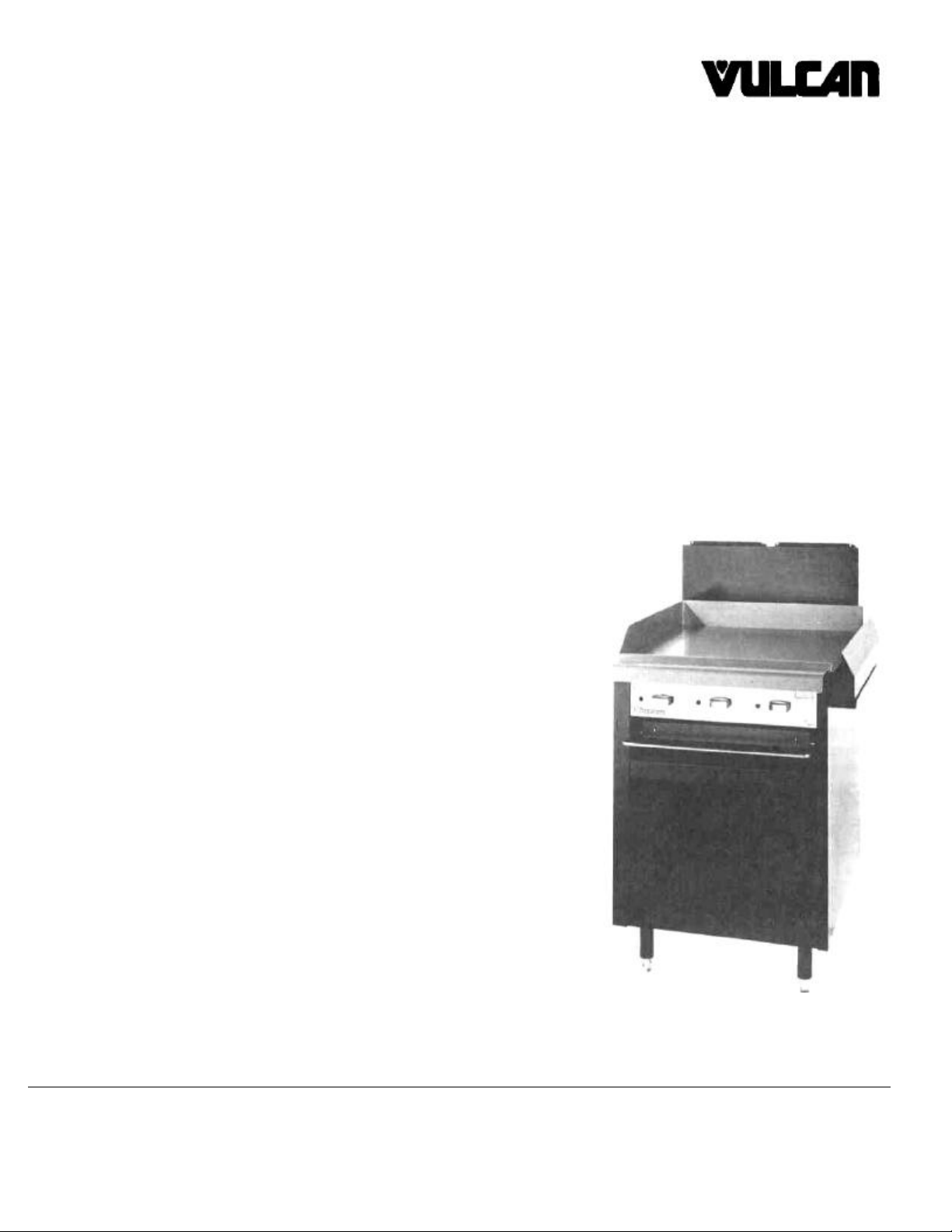
BROILER/GRIDDLE
MODEL 100L-77R
VULCAN-HART CORPORATION, 3600 NORTH POINT BOULEVARD, BALTIMORE, MARYLAND 21222
Page 2

IMPORTANT
Operating information for this equipment has been prepared for use by qualified and/or authorized operating
personnel.
All installation and service on this equipment is to be performed by qualified, certified, licensed and or
authorized installation or service personnel, with the exception of any marked with a ^ in front of the part
number.
Service may be obtained by contacting the Factory Service Department, Factory Representative or Local
Service Agency.
DEFINITIONS
QUALIFIED AND/OR AUTHORIZED OPERATING PERSONNEL
Qualified or authorized operating personnel are those who have carefully read the information in this manual
and are familiar with the equipment s functions or have had previous experience with the operation of the
equipment covered in this manual
QUALIFIED INSTALLATION PERSONNEL
Qualified installation personnel are individuals a firm, corporation or company which either in person or
through a representative are engaged in and are responsible for
1. The installation of gas piping from the outlet side of the gas meter, or the service regulator when the meter
is not provided, and the connection and installation of the gas appliance. Qualified installation personnel
must be experienced in such work, be familiar with all precautions required, and have complied with all
requirements of state or local authorities having jurisdiction Reference in the United States of America National Fuel Gas code ANSI Z223.1 (Latest Edition) In Canada-Canadian Standard CAN1-B149.1 NAT.
GAS (Latest Edition) or CAN1-B149.2 PROPANE (Latest Edition).
2. The installation of electrical wiring from the electric meter, main control box or service outlet to the electric
appliance Qualified installation personnel must be experienced in such work, be familiar with all
precautions required and have complied with all requirements of state or local authorities having
jurisdiction. Reference: In the United States of America-National Electrical Code ANSI NFPA No. 70
(Latest Edition). In Canada-Canadian Electrical Code Part 1 CSA-C22.1 (Latest Edition).
QUALIFIED SERVICE PERSONNEL
OPERATING, INSTALLATION AND SERVICE PERSONNEL
Qualified service personnel are those who are familiar with Vulcan equipment who have been endorsed by
the Vulcan-Hart Corporation All authorized service personnel are required to be equipped with a complete set
of service parts manuals and stock a minimum amount of parts for Vulcan equipment.
SHIPPING DAMAGE CLAIM PROCEDURE
For your protection, please note that equipment in this shipment was carefully inspected and packed by
skilled personnel before leaving the factory The transportation company assumes full responsibility for safe
delivery upon acceptance of this shipment.
If shipment arrives damaged:
1. VISIBLE LOSS OR DAMAGE — Be certain this is noted on freight bill or express receipt and signed by
person making delivery.
2. FILE CLAIM FOR DAMAGES IMMEDIATELY — Regardless of extent of damage.
3. CONCEALED LOSS OR DAMAGE — If damage is unnoticed until merchandise is unpacked, notify
transportation company or carrier immediately, and file “concealed damage" claim with them. This should
be done within (15) days of date of delivery is made to you. Be sure to retain container for inspection.
We cannot assume responsibility for damage or loss incurred in transit. We will, however, be glad to
furnish you with necessary documents to support your claim.
PLEASE RETAIN THIS MANUAL FOR FUTURE REFERENCE
Page 3

IMPORTANT NOTES FOR ALL VULCAN APPLIANCES
1. These units are produced with the best possible workmanship and material. Proper installation is vital if best performance and
appearance are to be achieved. Installer must follow the installation instructions carefully.
2. Information on the construction and installation of ventilating hoods may be obtained from the “Standard for the installation of
equipment for the removal of smoke and grease laden vapors from commercial cooking equipment,” NFPA No. 96 (latest
edition) available from the National Fire Protection Association, Battery March Park, Quincy MA 02269.
3. For an appliance equipped with a flexible electric supply cord, the cord is equipped with a three prong (grounding) plug. This
grounding plug is for your protection against shock hazard and should be plugged directly into a properly grounded three prong
receptacle. Do not cut or remove the grounding prong from this plug. If the appliance is not equipped with a grounding plug, and
electric supply is needed, ground the appliance by using the ground lug provided (refer to the wiring diagram).
(FOR GAS APPLIANCES ONLY)
4. Do not obstruct the air flow into and around the appliance. This air flow is necessary for proper combustion of gases and for
ventilation of the appliance. Provisions for ventilation of incoming air supply for the equipment in the room must be in
accordance with National Fuel Gas Code ANSI Z223.1 (latest edition).
5. Do not obstruct the flow of flue gases from the flue duct (when so equipped) located on the rear (or sides) of the appliance. It is
recommended that the flue gases be ventilated to the outside of the building through a ventilation system installed by qualified
personnel.
6. For an appliance equipped with casters, (1) the installation shall be made with a connector that complies with the Standard for
Connectors for Movable Gas Appliances, ANSI Z21 69 (latest edition), and Addenda, Z21.69a (latest edition), and a quickdisconnect device that complies with the Standard for Quick-Disconnect Devices for Use With Gas Fuel, ANSI Z21.41 (latest
edition), and Addenda, Z21.41a (latest edition) and Z21.41b (latest edition) and (2) adequate means must be provided to limit
the movement of the appliance without depending on the connector and the quick-disconnect device or its associated piping to
limit the appliance movement.
If disconnection of the restraint is necessary, reconnect this restraint after the appliance has been returned to its originally
installed position.
7. The appliance and its individual shutoff valve must be disconnected from the gas supply piping system during any pressure
testing of that system at test pressures in excess of 1/2 psig (3.45 k Pa).
8. The appliance must be isolated from the gas supply system by closing its individual manual shutoff valve during any pressure
testing of the gas supply system at test pressures equal to or less than 1/2 psig (3.45 k Pa)
CAUTIONS
FOR YOUR SAFETY
DO NOT STORE OR USE GASOLINE OR OTHER FLAMMABLE VAPORS AND LIQUIDS
IN THE VICINITY OF THIS EQUIPMENT OR ANY OTHER APPLIANCE.
1. KEEP THE APPLIANCE FREE AND CLEAR FROM ALL COMBUSTIBLE SUBSTANCES.
2. IN THE EVENT A GAS ODOR IS DETECTED, SHUT UNIT(S) DOWN AT THE MAIN
SHUTOFF VALVE AND CONTACT THE LOCAL GAS COMPANY OR GAS SUPPLIER FOR
SERVICE.
3. POST IN A PROMINENT LOCATION, INSTRUCTIONS TO BE FOLLOWED IN THE EVENT
THE SMELL OF GAS IS DETECTED. THIS INFORMATION MAY BE OBTAINED FROM A
LOCAL GAS SUPPLIER.
Page 4

VULCAN 100L-77 BROILER/GRIDDLE
DESCRIPTION
PAGE
INSTALLATION, SERVICE AND PARTS MANUAL
Your Vulcan broiler griddle is produced with the best
possible workmanship and material. Proper usage and
maintenance will result in many years of satisfactory
performance.
DEFINITIONS OF PERSONNEL (Operating, Installation & Service) and
SHIPPING DAMAGE CLAIM PROCEDURE
CAUTIONS 1
INDEX 2
CONNECTING UNIT TO GAS 3
MAIN BURNER & PILOT ADJUSTMENT 3-4
TROUBLE SHOOTING 4
REPLACEMENT PARTS LIST 5-6
REVISION PAGE (Inside Back Cover)
A rating plate is located on the inside lower left hand wall
of the broiler cabinet. The rating plate states the model
number, serial number and type of gas the unit requires.
The manufacturer suggests that you thoroughly read this
entire manual and carefully follow all of the instructions
provided.
vital if best performance and appearance is to be
achieved. Please follow the installation instructions
carefully.
INDEX
(Inside Front Cover)
Vulcan units are produced with the best possible
workmanship and material. Proper installation is
WARNING: back and sides of unit must be installed
6" from combustible construction material.
CAUTION
FROM THE TERMINATION OF THE APPLIANCE FLUE VENT TO THE FILTERS OF THE HOOD VENTING SYSTEM, AN 18 INCH
MINIMUM CLEARANCE MUST BE MAINTAINED.
REFERENCE: ANSI/NFPA 96-1980 4-1.2.2.2. OF THE NATIONAL FIRE PROTECTION ASSOCIATION, INC., BATTERYMARCH PARK,
QUINCY, MA 02269 AND NATIONAL BUILDING CODE 1976 SEC. 1015.7b (2) OF THE AMERICAN INSURANCE ASSOCIATION,
ENGINEERING AND SAFETY SERVICE, 85 JOHN STREET, NEW YORK, N.Y. 10038.
2
Page 5

CONNECTING UNIT TO GAS
BURNER & PILOT ADJUSTMENT
1. CONNECT UNIT TO GAS
Each unit is factory equipped for use with the type of gas
indicated on the range rating plate. Check type of gas supply
available.
NOTE:
A. Pipe joint compounds used when connecting appliances to
gas should be resistant to the action of L.P. propane gases.
B. Pipe joints should be tested for leaks with a soap and water
solution before operating the unit.
4. If the pilot fails to light, turn off the gas, wait 5 minutes and
repeat steps 1 thru 3.
NIGHTLY SHUTDOWN
1. Turn the burner valve off, the pilot will remain lit.
SEASONAL SHUTDOWN
1. Turn the burner valve off, the pilot will remain lit.
2. Extinguish the pilot.
3. Turn the main gas supply off.
C. Standard units for use on Natural or Mixed Gases are
equipped with fixed orifices and pressure regulator with a preset outlet pressure of 3.7" W.C. (Water Column) Units for use on
propane gas are equipped with fixed orifices and pressure
regulator with a pre-set outlet pressure of 10.0" W.C.
2. PRESSURE REGULATOR
When connecting unit to gas supply, pressure regulator must be
mounted vertically as shown in Detail A to insure the proper
preset outlet pressure. If regulator is mounted in any other
position, the outlet pressure must be reset.
NOTE:
Do not obstruct leak limiter on gas pressure regulator.
3. BURNER AND PILOT ADJUSTMENTS
Standard units are equipped with a pressure regulator and
should require no further adjustments.
4. LIGHTING BROILER/GRIDDLE PILOT
1. Turn the main gas supply on.
2. Turn the burner valve on and purge air from lines
Turn the valve off.
3. Using a taper, light the pilot.
5. Pilot Adjustment—Turn one burner on to remove air from
the line. Turn burner off when gas begins to flow. Light top pilots
and adjust, if necessary, by rotating adjusting screw in pilot
valve on manifold. (Clockwise to decrease and counterclockwise to increase flame.)
6. Burner Adjustment—The efficiency of the unit depends on
a rather delicate balance between the supply of air and volume
of gas so that complete combustion is achieved. Whenever this
balance is disturbed poor operating characteristics and excessive gas consumption occur.
7. Air Supply—Is controlled by an air shutter on the front of the
burner. The air shutter on the front of the burner. The air shutter
openings should be increased until the flame on the burner
begins to "lift". The air shutter should then be closed slightly and
locked in place. A yellow streaming flame is an indication of
insufficient air. This condition can be corrected by increasing the
air shutter opening.
DETAIL A
3
Page 6

CONNECTING UNIT TO GAS
BURNER AND PILOT ADJUSTMENT
8. CERAMICS—Vulcan Restaurant Range Broilers are equipped
with ceramic radiants for the most efficient operation. These
radiants are packed separately. Parts page shows ceramics in
place.
TROUBLE SHOOTING
Burner Operation
Improper Burner Combustion
Excessive Valve Handle Temperatures Improper Ventilation
Sticking Burner Valves
Poor Ignition
Insufficient Gas Input
Poor Air-Gas Adjustment
Restriction In Pilot Orifice
Restriction In Burner Ignition Port
9. ORIFICE DAT A
Regulated Nat. & Mixed Propane
Griddle/Broiler 48 48 63
4
Page 7

PARTS LIST
REPLACEMENT PARTS ORDERING: The following
information must accompany a replacement parts
order or it cannot be filled.
A. Model and Style or Serial Number.
B. Appliance Finish, Black, Stainless Steel, etc.
(if applicable to part to be replaced.)
This information can be found on the instruction
plate on the unit.
Parts may be ordered from your dealer, service
agency, or the factory.
Orders to the factory should be addressed to
Vulcan-Hart Corp., 3600 North Point Blvd.,
Baltimore, MD 21222.
5
Page 8

PARTS LIST
DESCRIPTION 100L-77R
6.
BURNER VALVE HANDLE 113157-1
14.
LIGHTER VALVE 104193-1
+15.
BROILER BURNER VALVE (LESS HOOD) 404076
OVEN HOOD (NAT ) 418051-48
OVEN HOOD (PROPANE) 418051-63
41.
BURNER ASSEMBLY 112793-G1
42.
SIDE CERAMICS 104146 1
43.
CENTER CERAMICS 104145-1
44.
GRID PAN ASSEMBLY 108766-G1
45.
GRID 104149-2
46.
BURNER TRAY ASSEMBLY (NOT SHOWN) 111607-G1
47.
PILOT TUBING 110662-G1
50.
BURNER TRAY HANDLE 113343-1
BURNER TRAY HANDLE (SS) 113343-2
64.
GREASE COLLECTOR SUPPORT 113317-1
GREASE COLLECTOR SUPPORT (SS) 113317-2
+ SPECIFY TYPE OF GAS (SS) STAINLESS STEEL
6
Page 9

MANUAL PART NO.:
113998
-1
REV. BLOCK
FOR MODEL: 100L-77R
DESCRIPTION: BROILER/GRIDDLE
INSTALLATION, SERVICE
AND PARTS MANUAL
REV.#
DATE SIG.
2 3/82 DML
3 8/84 DML
 Loading...