

VTS Medical Systems VOLCANO VR Series, VOLCANO VR1, VOLCANO VR2, VOLCANO VR3, VOLCANO VR Mini Technical Documentation Manual
...
EN
Check us on
VR-ver.2.1 (09.2017)
Technical documentation
VOLCANO VR Mini
VOLCANO VR1
VOLCANO VR2
VOLCANO VR3
VOLCANO VR-D

VOLCANO VR Mini
VOLCANO VR1
VOLCANO VR2
VOLCANO VR3
VOLCANO VR-D
ORIGINAL INSTRUCTION
TABLE OF CONTENTS
1. INTRODUCTION
1.1 Precautions, requirements, recommendations
1.2 Transport
1.3 Initial steps taken before instalation
2. DESIGN, USE, PRINCIPLE OF OPERATION
2.1 Intended use
2.2 Principle of operation
2.3 Construction of the device
2.4 Overall dimensions
3. TECHNICAL DATA
4. INSTALLATION
4.1 Installation with a bracket
4.2 Installation instructions
5. AUTOMATIC DEVICES
5.1 Automatic devices
6. START-UP, OPERATION, MAINTENANCE
6.1 Start-up
6.2 Operation and maintenance
7. OCCUPATIONAL HEALTH AND SAFETY
INSTRUCTIONS
8. CODING
9. TECHNICAL INFORMATION TO THE REGULATION
(EU) NO 327/2011 IMPLEMENTING DIRECTIVE
2009/125/EC
10. SERVICE
10.1 Procedures in case of defects
10.2 Complaint procedure
2
1. INTRODUCTION
1.1 PRECAUTIONS, REQUIREMENTS, RECOMMENDATIONS
Read the documentation carefully, install and use the equipment according to the specications, and follow all the safety regulations in order to ensure proper and safe use of the device. Any
use that is incompatible with these instructions can cause serious injuries. Restrict access by unauthorized persons and train the operational personnel.The term operational personnel refers
to people who are suitably trained and have appropriate experience and knowledge of relevant norms, documentation and occupational health and safety regulations, and are authorized to
conduct the required work and can identify possible threats and avoid them. This operation and maintenance manual, which is delivered with the device, includes detailed information on all
possible congurations of the heaters, examples of their assembly, start, use, repair and maintenance. To operate this device correctly, this manual includes instructions sufcient for qualied
personnel.The documentation should be placed close to the device for ease of access by the service team. The manufacturer reserves the right to introduce changes to the
manual or the specications of the device, which may alter its operation, without prior notice. VTS POLSKA Sp. z o.o. shall not be held liable for current maintenance, servicing,
programming, damage caused by standstill of the device awaiting warranty service, any damage to customer’s possessions other than the device, or faults resulting from the wrong assembly or
use of the device.
1.2 TRANSPORT
Prior to the installing and taking the device out of the cardboard box, it is required to check whether the cardboard box has not been damaged in any way and/or the adhesive tape (installed
at the company) has not been broken off or cut. It is recommended to check whether the device’s casing has not been damaged in transport. Should any of the above situation occur, please
contact us through telephone or e-mail: Tel. 0 801 080 073, email: vts.pl@vtsgroup.com, fax: (+48) 12 296 50 75. The device should be transported by two people. Use appropriate tools,
when transporting the device, so as to avoid the damaging of goods and potential hazard to health.
1.3 INITIAL STEPS TAKEN BEFORE THE INSTALLATION
Record the serial number of the device in the warranty card, prior to the commencement of the installation process. It is required to properly ll-in the warranty card, after the completion
of the assembly. Prior to the commencing of any installation or maintenance work, it is required to disconnect power supply and protect it against unintentional activation.
2. STRUCTURE, INTENDED USE, PRINCIPLE OF OPERATION
2.1 INTENDED USE
VOLCANO VR has been designed to ensure ease of use and optimum performance.
The device is available in four versions:
VOLCANO VR Mini (3-20 kW, 2100 m3/h)
VOLCANO VR 1 (5-30 kW, 5300 m3/h)
VOLCANO VR 2 (8-50 kW, 4850 m3/h)
VOLCANO VR 3 (13-75 kW, 5700 m3/h)
VOLCANO VR-D (6500 m3/h)
VOLCANO combines state-of-the-art technology, innovative design and high effectiveness. Unique technical solutions such as the design of the heat exchanger, improved fan and increased
range of air stream, allow the VOLCANO heater to achieve optimal heating power, perfect for the size and type of room. APPLICATION: production halls, warehouses, wholesale outlets, sports
facilities, greenhouses, supermarkets, church buildings, farm buildings, workshops, health care facilities, pharmacies, hospitals. MAIN ADVANTAGES: high effectiveness, low maintenance
costs, full parameter control, easy and quick assembly.
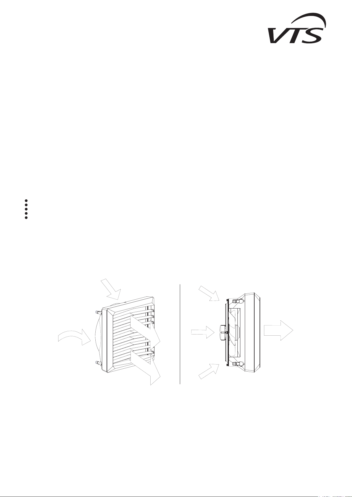
2.2 PRINCIPLE OF OPERATION
The heating medium (hot water) gives up heat to the heat exchanger using a highly developed heat exchanger, ensuring great heating power (Volcano VR Mini – 3-20 kW, VR 1 – 5-30 kW,
VR 2 – 8-50 kW, VR 3 – 13-75 kW). A highly effective axial fan (1100-5700 m3/h) draws air in from the room, pumps it through the heat exchanger and then sends it back into the room.
Volcano VR-D de-straties the heated air from the sub-ceiling zone to the above-ground zone. Hot air exhaust results in a leveling of the temperature gradient in particular air layers and
contributes to reducing the costs of heating by lowering the temperature in the ceiling zone, thus limiting heat loss through the roof. The VOLCANO VR-D de-stratier will be the most effective
in combination with VR Mini, VR1, VR2 and VR3 air heaters. Cooperation of both of these device types will allow for achieving optimal temperature comfort fast due to the support of the heating
system through more efcient distribution of hot air.
3
VOLCANO VR Mini
310 mm 395 mm
381 mm
381 mm
355 mm 425 mm
550 mm
550 mm
VOLCANO VR1
VOLCANO VR2
VOLCANO VR3
VOLCANO VR-D
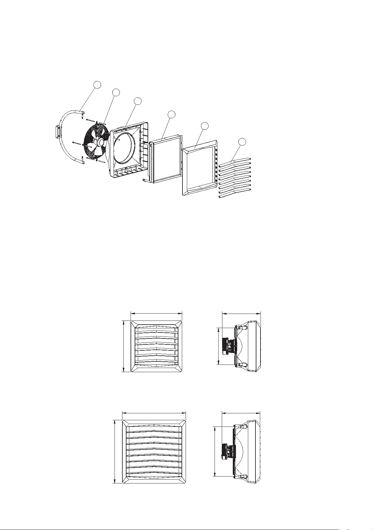
2.3 DEVICE STRUCTURE (VOLCANO)
5
2
3
1. HEAT EXCHANGER;
2. AXIAL FAN;
3. COVER;
4. AIR GUIDES;
5. SAMPLE CONSOLE
1
3
4
EN: HEAT EXCHANGER: maximum parameters of a heating medium for a heat exchanger are: 130°C, 1,6MPa. Aluminium and copper construction using copper tubes, coil pipe and
1.
aluminium lamellas. Connecting ferrules (male thread ¾”) are on the back panel of the unit. Our series of types includes a single-row heat exchanger in VOLCANO VR1 5-30 kW and two-row
heat exchanger in VOLCANO VR Mini 3-20kW and VOLCANO VR2 8-50kW and in VOLCANO VR3 13-75kW - three-row heat exchanger.
AXIAL FLOW FAN: maximum working temperature is 60°C, nominal power supply voltage is 230V/50Hz. EC Engine protection is IP44, insulation class F. Air feed is performed by the axial
2.
flow fan, which is secured with a protective grate. Adequate blade prole and proper bearings guarantee silent and unfailing operation of the device. High engine power allows for achieving
high efciency at low power consumption rates, maintaining full air feed regulation. Properly proled housing lowers the noise emission levels, which makes the device particularly user-friendly,
suitable for buildings with higher acoustic requirements.
HOUSING: consists of the body and the front panel, made of high quality plastic guaranteeing compatibility with devices powered by heating medium with temperature parameter up to 130°C.
3.
Colorful side panels allow for matching the device color to the interior décor. Volcano VR-D operates circulation air, improving its distribution and performing the de-stratication function.
AIR GUIDES: allow the hot air stream to be directed in 4 directions. Optimum air stream range and direction are achieved through the special fan blade prole.
4.
ASSEMBLY CONSOLE: an element of additional equipment - its ergonomic, light structure allows for rotating the device on the horizontal plane for -60°÷0÷60°, to direct the stream of hot air
5.
wherever it is necessary.
2.4 OVERALL DIMENSIONS
EC
VOLCANO VR Mini
530 mm
530 mm
395 mm
381 mm
EC
VOLCANO VR1, VR2, VR3, VR-D
700 mm
425 mm
700 mm
550 mm
4
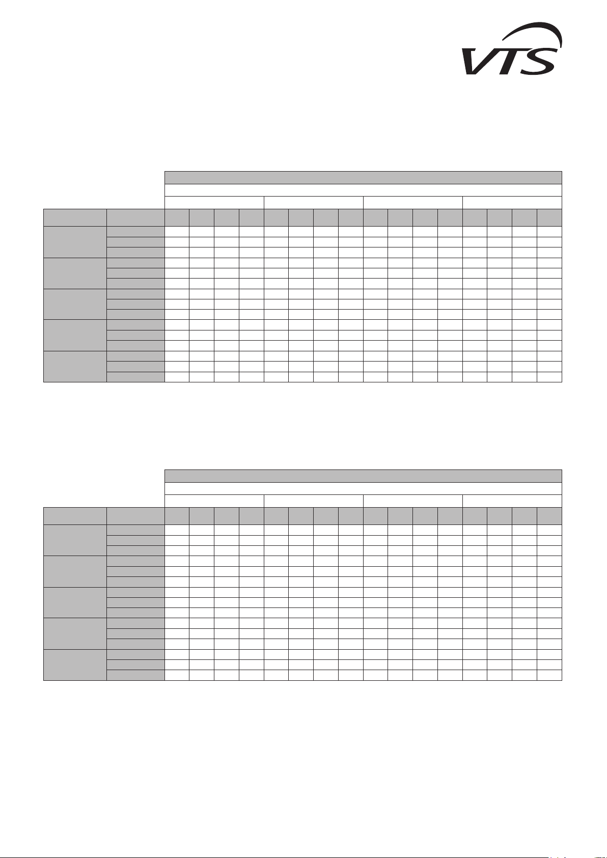
3. TECHNICAL DATA
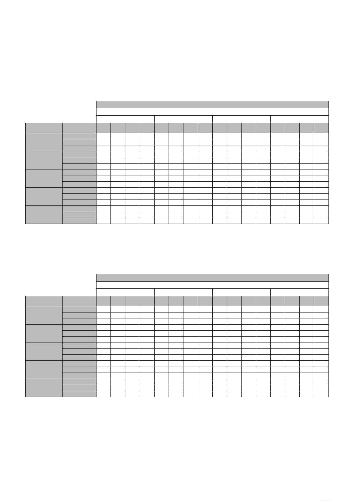
Tz – inlet water temperature; Tp – outlet water temperature; Tp1 – inlet air temperature; Tp2 – outlet air temperature; Pg – heating capacity; Qw – water flow; Qp- air flow rate; Δp –
pressure drop in the heat exchanger
Volcano VR Mini
Parameters Tz/Tp [°C]
90/70 [°C] 80/60 [°C] 70/50 [°C] 50/30 [°C]
Tp1
[°C]
0
5
10
15
20
Qp
[m³/h]
2100 20.7 29.5 0.92 13.9 17.9 25.4 0.79 10.7 15.1 21.4 0.66 7.9 9.2 13.1 0.4 3.4
1650 18.1 32.6 0.8 10.7 15.6 28.2 0.69 8.3 13.1 23.7 0.58 6.1 8 14.6 0.35 2.6
1100 14.1 38.3 0.63 6.8 12.2 33.2 0.54 5.3 10.3 27.9 0.45 3.9 6.3 17.2 0.28 1.7
1650 16.9 35.6 0.75 9.5 16.6 28.6 0.73 9.3 13.7 24.5 0.6 6.6 7.6 16.1 0.34 2.5
2100 19.4 32.6 0.86 12.3 14.5 31.1 0.64 7.2 12 26.6 0.53 5.2 6.8 17.4 0.3 2
1100 13.3 40.9 0.59 6 11.3 35.8 0.5 4.6 9.4 30.5 0.41 3.3 5.4 19.6 0.23 1.3
2100 18.1 35.7 0.8 10.8 15.3 31.7 0.67 8 12.4 27.6 0.54 5.5 6.4 19.1 0.28 1.7
1650 15.8 35.5 0.7 8.4 13.3 34.1 0.59 6.2 10.8 29.5 0.47 4.3 5.6 20.1 0.24 1.4
1100 12.4 43.5 0.55 5.3 10.4 38.3 0.46 3.9 8.5 33 0.37 2.8 4.4 21.9 0.19 0.9
2100 16.8 38.8 0.74 9.4 13.9 34.8 0.61 6.7 11 30.7 0.48 4.4 4.9 22 0.22 1.1
1650
1100 11.5 46.1 0.51 4.6 9.5 40.9 0.42 3.3 7.6 35.5 0.33 2.2 3.3 24.1 0.15 0.5
2100 15.5 41.9 0.69 8 12.6 37.9 0.56 5.6 9.7 33.7 0.42 3.5 3.3 24.7 0.14 0.5
1650 13.5 44.3 0.6 6.2 11 39.8 0.48 4.3 8.4 35.2 0.37 2.7 2.8 25.1 0.12 0.4
1100 10.6 48.6 0.47 4 8.6 43.4 0.38 2.8 6.6 38 0.29 1.8 1.9 25.2 0.08 0.2
Pg
Tp2
Qw
Δp
Pg
Tp2
Qw
Δp
Pg
T
Qw
Δp
[kW]
[°C]
[m³/h]
[kPa]
[kW]
[°C]
[m³/h]
[kPa]
[kW]
14.6 41.4 0.65 7.3 12.1 37 0.54 5.2 9.6 32.4 0.42 3.5 4.3 22.8 0.19 0.9
[°C]
p2
[m³/h]
[kPa]
Pg
[kW]
Tp2
[°C]
Qw
[m³/h]
Δp
[kPa]
Tz – inlet water temperature; Tp – outlet water temperature; Tp1 – inlet air temperature; Tp2 – outlet air temperature; Pg – heating capacity; Qw – water flow; Qp- air flow rate; Δp –
pressure drop in the heat exchanger
Volcano VR1
Parameters Tz/Tp [°C]
90/70 [°C] 80/60 [°C] 70/50 [°C] 50/30 [°C]
Tp1
[°C]
0
5
10
15
20
Qp
[m³/h]
5300 29.9 16.8 1.33 26 25.8 14.5 1.14 20 21.7 12.2 0.95 14.6 13.2 7.5 0.58 6.2
3900 25.4 19.4 1.12 19.1 21.9 16.7 0.97 14.7 18.4 14.1 0.81 10.8 11.3 8.6 0.49 4.6
2800 21.2 22.6 0.94 13.6 18.3 19.5 0.81 10.5 15.4 16.4 0.68 7.8 9.4 10.1 0.41 3.3
5300 28 20.8 1.24 23 23.9 18.4 1.05 17.3 19.7 16.1 0.87 12.3 11.3 11.3 0.49 4.6
3900 23.8 23.2 1.05 16.9 20.3 20.5 0.9 12.8 16.8 17.8 0.74 9.1 9.6 12.3 0.42 3.4
2800 19.9 26.2 0.88 12.1 16.9 23.1 0.75 9.1 14 19.9 0.62 6.6 8 13.6 0.35 2.5
5300 26.1 24.7 1.16 20.2 22 22.4 0.97 14.8 17.8 20 0.78 10.2 9.2 15.2 0.4 3.2
3900 22.2 27 0.98 14.9 18.7 24.3 0.82 10.9 15.1 21.6 0.66 7.6 7.9 16 0.34 2.4
2800 18.5 29.7 0.82 10.6 15.6 26.6 0.69 7.8 12.7 23.5 0.56 5.4 6.6 17 0.29 1.8
5300 24.2 28.6 1.07 17.5 20 26.3 0.88 12.5 15.8 23.9 0.7 8.2 7.2 19 0.31 2
3900 20.5 30.7 0.91 12.9 17 28 0.75 9.2 13.5 25.3 0.59 6.1 6.1 19.7 0.27 1.5
2800 17.2 33.3 0.76 9.2 14.2 30.2 0.63 6.6 11.3 27 0.5 4.4 5.1 20.4 0.22 1.1
5300 22.2 32.5 0.99 15 18.1 30.2 0.8 10.3 13.8 27.8 0.61 6.4 5 22.8 0.22 1.1
3900 18.9 34.5 0.84 11.1 15.4 31.8 0.68 7.6 11.8 29 0.52 4.8 4.2 23.2 0.18 0.8
2800 15.8 36.8 0.7 7.9 12.9 33.7 0.57 5.5 9.9 30.5 0.43 3.5 3.5 23.7 0.15 0.6
Pg
[kW]
Tp2
[°C]
Qw
[m³/h]
Δp
[kPa]
Pg
[kW]
Tp2
[°C]
Qw
[m³/h]
Δp
[kPa]
Pg
[kW]
T
[°C]
Qw
Δp
p2
[m³/h]
[kPa]
Pg
[kW]
Tp2
[°C]
Qw
[m³/h]
Δp
[kPa]
5
VOLCANO VR Mini
VOLCANO VR1
VOLCANO VR2
VOLCANO VR3
VOLCANO VR-D
Tz – inlet water temperature; Tp – outlet water temperature; Tp1 – inlet air temperature; Tp2 – outlet air temperature; Pg – heating capacity; Qw – water flow; Qp- air flow rate; Δp –
pressure drop in the heat exchanger
Volcano VR2
Parameters Tz/Tp [°C]
90/70 [°C] 80/60 [°C] 70/50 [°C] 50/30 [°C]
Tp1
[°C]
0
5
10
15
20
Qp
[m³/h]
4850 50.1 30.7 2.21 23.8 43.1 26.5 1.9 18.3 36.2 22.3 1.59 13.5 22.3 13.7 0.97 5.7
3600 41.9 34.7 1.86 17.2 36.5 30 1.6 13.3 30.5 25.3 1.34 9.8 18.8 15.6 0.82 4.2
2400 32.7 40.6 1.45 10.8 28.3 35.2 1.25 8.4 23.9 29.7 1.05 6.2 14.8 18.4 0.64 2.7
4850 46.7 33.7 2.07 21.1 39.9 29.5 1.76 15.9 33.1 25.3 1.45 11.4 19 16.7 0.83 4.3
3600 39.3 37.5 1.74 15.2 33.6 32.8 1.48 11.5 27.9 28.1 1.22 8.3 16.1 18.3 0.7 3.1
2400 30.6 43.1 1.36 9.6 26.2 37.6 1.16 7.3 21.8 32.1 0.96 5.3 12.6 20.7 0.55 2
4850 43.6 36.8 1.93 18.5 36.7 32.6 1.62 13.6 29.8 28.4 1.31 9.4 15.6 19.6 0.68 3
3600 36.6 40.4 1.62 13.4 30.9 35.6 1.36 9.9 25.2 30.9 1.11 6.8 13.2 21 0.58 2.2
2400
4850 40.4 39.8 1.79 16 33.5 35.6 1.48 11.5 26.6 31.3 1.17 7.6 12.2 22.5 0.53 1.9
3600
2400
4850 37.2 42.8 1.65 13.7 30.3 38.6 1.34 9.5 23.3 34.3 1.02 5.9 8.4 25.2 0.37 1
3600 31.3 45.9 1.39 10 25.5 41.1 1.13 6.9 19.7 36.3 0.86 4.3 7 25.8 0.31 0.7
2400
Pg
Tp2
Qw
Δp
Pg
Tp2
Qw
Δp
Pg
T
Qw
Δp
[kW]
[°C]
[m³/h]
[kPa]
[kW]
[°C]
[m³/h]
[kPa]
[kW]
28.6 45.5 1.27 8.4 24.2 40 1.07 6.3 19.7 34.5 0.87 4.4 10.4 22.9 0.45 1.4
34 43.1 1.51 11.6 28.2 38.4 1.25 8.3 22.4 33.6 0.99 5.5 10.3 23.5 0.45 1.4
26.5 48 1.18 7.3 22.1 42.5 0.98 5.3 17.6 36.9 0.77 3.5 8 25 0.35 0.9
24.5 50.4 1.09 6.3 20 44.8 0.88 4.4 15.5 39.2 0.68 2.8 5.3 26.6 0.23 0.4
[°C]
p2
[m³/h]
[kPa]
Pg
[kW]
Tp2
[°C]
Qw
[m³/h]
Δp
[kPa]
Tz – inlet water temperature; Tp – outlet water temperature; Tp1 – inlet air temperature; Tp2 – outlet air temperature; Pg – heating capacity; Qw – water flow; Qp- air flow rate; Δp –
pressure drop in the heat exchanger
Volcano VR3
Parameters Tz/Tp [°C]
90/70 [°C] 80/60 [°C] 70/50 [°C] 50/30 [°C]
Tp1
[°C]
0
5
10
15
20
Qp
[m³/h]
5700 75.1 39 3.31 32.6 64.5 33.8 2.85 25.1 54.3 28.4 2.39 18.4 33.6 17.6 1.46 7.8
4100 60.6 44.1 2.69 22 52.5 38.2 2.32 17 44.3 32.2 1.95 12.5 27.5 20 1.2 5.4
3000 49.5 49.2 2.19 15 42.9 42.7 1.89 11.6 36.3 36.1 1.59 8.6 22.6 22.5 0.98 3.7
5700 69.9 41.6 3.1 28.9 59.8 36.3 2.64 21.7 49.6 31 2.18 15.5 28.7 20 1.25 5.8
4100 56.8 46.3 2.52 19.5 48.7 40.4 2.15 14.8 40.5 34.4 1.78 10.6 23.5 22.1 1.02 4
3000 46.4 51.1 2.06 13.3 39.8 44.6 1.76 10.1 33.1 37.9 1.46 7.3 19.3 24.2 0.84 2.8
5700 65.2 44.1 2.89 25.3 55 38.8 2.43 18.6 44.8 33.4 1.97 12.8 23.7 22.4 1.03 4.1
4100 53 48.6 2.35 17.1 44.9 42.6 1.98 12.7 36.6 36.6 1.61 8.8 19.4 24.1 0.84 2.8
3000 43.3 53.1 1.92 11.7 36.7 46.5 1.62 8.7 30 39.8 1.32 6.1 15.9 25.8 0.69 2
5700 60.4 46.6 2.68 21.9 50.2 41.3 2.22 15.7 40 35.9 1.76 10.3 18.4 24.6 0.8 2.6
4100 49.2 50.8 2.18 14.9 41 44.8 1.81 10.7 32.7 38.8 1.44 7.1 15.1 26 0.66 1.8
3000 40.2 55 1.78 10.2 33.6 48.4 1.48 7.4 26.8 41.6 1.18 4.9 12.4 27.3 0.54 1.2
5700 55.6 49.1 2.47 18.8 45.4 43.8 2 13 35 38.3 15.4 8.1 12.8 26.7 0.56 1.3
4100 45.3 53 2.01 12.8 37.1 47 1.64 8.9 28.7 40.9 1.26 5.6 10.4 27.5 0.45 0.9
3000 37.1 56.9 1.64 8.8 30.4 50.2 1.34 6.1 23.6 43.4 1.04 3.9 8.3 28.2 0.36 0.6
Pg
[kW]
Tp2
[°C]
Qw
[m³/h]
Δp
[kPa]
Pg
[kW]
Tp2
[°C]
Qw
[m³/h]
Δp
[kPa]
Pg
[kW]
T
[°C]
Qw
Δp
p2
[m³/h]
[kPa]
Pg
[kW]
Tp2
[°C]
Qw
[m³/h]
Δp
[kPa]
6

Parameter Unit of measure
Number of rows in the heater 2 1 2 3 ---
Maximum air ow rate m³/h 2100 5300 4850 5700 6500
Heating power range kW 3-20 5-30 8-50 13-75 -
Maximum temperature of the heating agent °C 130 -
Maximum operating pressure* MPa 1.6 -
Maximum horizontal air stream range m 14 23 22 25 28
Maximum vertical air stream range m 8 12 11 12 15
Water capacity dm³ 1.12 1.25 2.16 3.1 -
Ferrule diameter " 3/4 -
Weight of the device kg 14 21 21,5 24,5 15,5
Power supply voltage V/Hz 1 ~ 230/50
VOLCANO
VR Mini
VOLCANO
VR1
VOLCANO
VR2
VOLCANO
VR3
VOLCANO
VR-D
Motor power EC kW 0.095 0.25 0.37
Motor current EC A 0.51 1.3 1.7
Motor speed rpm 1450 1430 1400
Motor IP EC 44
NOTE Data concerning VOLCANO working parameters for a heating agent with a different temperature can be provided upon request
7

VOLCANO VR Mini
VOLCANO VR1
VOLCANO VR2
VOLCANO VR3
VOLCANO VR-D
Volcano VR Mini
fan speed III II I
air flow m³/h 2100 1650 1100
noise level for Volcano EC* dB(A) 50 40 27
EC motor electric power** W 95 56 39
horizontal air stream range
vertical air stream range
* reference conditions: room volume 1500m³, measurement taken at a distance of 5m.
** EC motor electric power for the air ow mentioned in the table
fan speed III II I
air flow m³/h 5300 3900 2800
noise level for Volcano EC* dB(A) 54 49 38
EC motor electric power** W 250 190 162
horizontal air stream range
vertical air stream range
* reference conditions: room volume 1500m³, measurement taken at a distance of 5m.
** EC motor electric power for the air ow mentioned in the table
m
m
Volcano VR1
m
m
14 8 5
8 5 3
23 20 15
12 9 7
Volcano VR2
fan speed III II I
air flow m³/h 4850 3600 2400
noise level for Volcano EC* dB(A) 54 49 38
EC motor electric power** W 250 190 162
horizontal air stream range
vertical air stream range
* reference conditions: room volume 1500m³, measurement taken at a distance of 5m.
** EC motor electric power for the air ow mentioned in the table
m
m
Volcano VR3
fan speed III II I
air flow m³/h 5700 4100 3000
noise level for Volcano EC* dB(A) 55 49 43
EC motor electric power** W 370 285 218
horizontal air stream range
vertical air stream range
* reference conditions: room volume 1500m³, measurement taken at a distance of 5m.
** EC motor electric power for the air ow mentioned in the table
m
m
Volcano VR-D
fan speed III II I
air flow m³/h 6500 4600 3400
noise level for Volcano EC* dB(A) 56 50 43
EC motor electric power** W 370 285 218
horizontal air stream range
vertical air stream range
* reference conditions: room volume 1500m³, measurement taken at a distance of 5m.
** EC motor electric power for the air ow mentioned in the table
m
m
22 19 14
11 8 6
25 22 17
12 9 7
28 24 19
15 11 9
8

4. ASSEMBLY
OPT. 2-5m (Volcano V mini)
OPT. 2,5-8m (Volcano VR1, VR2, VR3)
OPT. 3-8m (Volcano V mini)
OPT. 3-11m (Volcano VR1, VR2)
OPT. 3-12m (Volcano VR3)
OPT. 6-15m (Volcano VR-D)
NOTE Installation location should be suitably selected with special consideration of potential loads and vibrations.
Prior to any installation or maintenance works, disconnect the device from the power supply and secure it against accidental power-up.
Use lters in the hydraulic system. Before you connect the hydraulic lines (especially supply lines) to the device, you should clean/rinse the installation by draining two litres out of it.
NOTE It is necessary to maintain a minimum distance of 0.4m from the wall or the ceiling; otherwise the device can malfunction, the fan can be damaged or its operating noise can increase.
If the device will be installed on a wall or under a ceiling, observe the following factors:
mounting height
* for vertical air guides adjustment
distance between units – recommended distance 6-12m (Volcano VR1, VR2, VR3), 3-7m (Volcano VR Mini), in order to ensure even hot air diffusion
OPT. 3-7m
OPT. 6-12m
(Volcano VR Mini)
(Volcano VR1, VR2, VR3)
OPT. 2-5m (Volcano VR Mini)
OPT. 2,5-8m (Volcano VR1, VR2, VR3)
range of air stream
* for horizontal air guide adjustment
** for symmetric air guide adjustment at an angle of 45°
Max. 14m* (Volcano V mini)
Max. 22m* (Volcano VR1, VR2)
Max. 25m* (Volcano VR3)
Max. 28m* (Volcano VR-D)
Max. 2m** (Volcano V mini)
Max. 13m* (Volcano VR1, VR2)
Max. 15m* (Volcano VR3, VR-D)
device noise level (depending on acoustic characteristics of a room)
operation mode of the heating device, e.g. it can also operate as an air mixing device preventing air stratication
direction of air distribution should be controlled in a way that prevents draughts. Air stream must not be directed at walls, brackets, girders, cranes, shelves, machines, etc.
9

VOLCANO VR Mini
supply
return
VOLCANO VR1
VOLCANO VR2
VOLCANO VR3
VOLCANO VR-D
Examples of arrangement of air heating units mounted on a wall
Top view
4.1 INSTALLATION WITH A BRACKET
The bracket is optional. In order to attach a bracket to the device, use crown drill bits to drill holes in the top and bottom panels of the heating unit (in places marked by 6), and insert sleeves
into the holes. Slide holder arms onto the sleeves. Insert M10x80mm screws into the top and bottom sleeves, and x the bracket position in relation to the heater while tightening the screws.
When you adjust the device in the right position, t plugs onto the bracket.
1
3
2
4
6
5
The bracket unit consists of:
1. ARM (1 piece); 2. HOLDER; 3. M8x60mm SCREW WITH A WASHER AND NUT FASTENING THE CLAMP (2 sets); 4. M8x60mm SCREW FASTENING THE HOLDER TO THE UNIT
HEATER (2 pieces); 5. PLUG (2 pieces); 6. MOUNTING SLEEVE (2 pieces)
rotation of the device when mounted on a console
120°
10

4.2 INSTALLATION INSTRUCTIONS AND MOUNTING DISTANCES
Installation of the heating medium supply system While installing the piping for the heating medium, secure the exchanger connection against twisting 1. The piping should not overload the
heater connections. It is possible to connect the piping with exible connections (adjustable angle of the airow).
VOLCANO VR Mini, VR1, VR2, VR3 VOLCANO VR Mini VOLCANO VR1, VR2, VR3, VR-D
425 mm
395 mm
return
381 mm
550 mm
supply
3
2
4
1
5
7
RETURN
SUPPLY
6
EXAMPLE OF A HYDRAULIC SYSTEM:
1. UNIT HEATER; 2. POWER-OPERATED VALVE; 3. VENT VALVE; 4. CUT-OFF VALVE; 5. FILTER; 6. CIRCULATION PUMP; 7. BOILER
11

VOLCANO VR Mini
VOLCANO VR1
VOLCANO VR2
VOLCANO VR3
VOLCANO VR-D
Heater vent/ heating medium drain
The device will be vented when you loosen the vent bolt 1 placed on the connection pipe. The heating medium is drained through the drain plug 2, placed on the bottom connection pipe. When
starting the device after the heating agent has been drained, remember to vent the heater.
You need to pay special attention to secure the device against water accidentally getting into the heater casing during the agent draining process.
1
2
Connecting to the power supply
NOTICE The installation must be equipped with disconnectors at all power supply poles. Recommended safety: overload disconnector VOLCANO VR Mini – 1 A, VOLCANO VR1, VR2 – 2
A, VOLCANO VR3, VR-D - 4A) and differential current safety. VOLCANO VR Mini, VR1, VR2, VR3, VR-D (fan) are equipped with a terminal block accepting 7 x 2,5 mm2 electric
wires. NOTICE We recommend connecting the wires to the terminal block with pre-installed bushings.
VOLCANO VR Mini, VR1, VR2, VR3, VR-D/
EC
Adjusting the air guides
Volcano air guides are mounted on the pivot 1, which provides smoothly change of air direction 4. In order to change position of air blade should turn it in both hands (grasping the edges of the
enclosure) to turn the blade at the same time on both pins.
Power supply: 3 x 1,5mm2
0-10Vdc: LiYCY 2x0,75 (shielded)
Control:
1
VOLCANO VR Mini, VR1, VR2, VR3, VR-D/
12

5. AUTOMATICS
74
5.1 ELEMENTS OF AUTOMATICS
Electric connections may only be made by well-trained electricians, and according to:
Occupational health and safety regulations
Assembly instructions
Technical documentation for each of the automatic elements
NOTE Before starting the assembly process and connecting the system, familiarize yourself with the original documentation attached to the automatic devices.
MODEL SCHEMAT DANE TECHNICZNE UWAGI
VTS: 1-4-0101-0457
CONTROLLER VOLCANO EC
VOLCANO EC CONTROLLER
● power supply: 1~230V +/-10%/50Hz
● maximum output current for valve or valves with actuator:
3(1)A
● power consumption: 1.5VA
● temperature set-up range: -10~+99°C
● parameters of the working conditions: 0~50°C
● relative humidity: 10-90%, without condensation
● display: blue backlight
● built-in sensor: NTC 10K
● outside sensor: option to connect the outside NTC sensor
● accuracy of measurement: + 1°C (measurement every +0.5°C)
● weekly calendar scheduling: 5+1+1
● operating mode: heating/cooling
● control options: automatic (0-10V)/manual (30%, 60%, 100%)
● clock: 24h
● displayed temperature: room temperature or set temperature
● programming of heating/cooling: two periods of heating per
24h (5+1+1) or continuous operation
● anti-frost protections: valve opening due room temperature
drop below 8°C
● ingress protection rating: IP30
● mounting method: flush mounted box 60mm
● operating: external keyboard
● maximum length of the signal cable: 120m
● casing: ABS
● dimensions/weight: 89x130x16 mm/0,19 kg
● external communication: MODBUS RTU
● suggested diameter of supply cable: 2x1mm
2
● Detailed description of the programmable temperature regulator, see
manual at www.vtsgroup.com
● Thermostat and programmable temperature regulator should be
installed in a visible location.
● Avoid places directly exposed to solar radiation, electromagnetic
waves, etc.
● The automation element drawings are only a visualization of sample
products.
HMI VR (VTS: 1-4-0101-0169)
74
VR EC (0-10V)
POTENTIOMETER
VTS: 1-4-0101-0453
HMI VR CONTROLLER
● power supply: 1~230V +/-10%/50Hz
● maximum output current for valve or valves with actuator:
3(1)A
● power consumption: 1.5VA
● temperature set-up range: 5~40°C
● parameters of the working conditions: 5~50°C
● relative humidity: 0,85
● display: gray, blue backlight
● built-in sensor: NTC 10K, 3950 Ohm at 25°C
● outside sensor: option to connect the outside NTC sensor
● accuracy of measurement: + 1°C (measurement every +0.5°C)
● weekly calendar scheduling: 5+1+1
● operating mode: heating/cooling
● control options: automatic (0-10V)/manual (30%, 60%, 100%)
● clock: 24h
● displayed temperature: room temperature or set temperature
● programming of heating/cooling: two periods of heating per
24h (5+1+1) or continuous operation
● anti-frost protections: valve opening due room temperature
drop below 8°C
● ingress protection rating: IP30
● mounting method: flush mounted box 60mm
● operating: external keyboard
● maximum length of the signal cable: 120m
● casing: ABS UL94-5 (re retardant plastic)
● colour: RAL 9016
● dimensions/weight: 86x86x54mm/0.12kg
● external communication: RS485 (MODBUS)
● suggested diameter of supply cable: 2x1mm
POTENTIOMETER VR EC (0-10V)
● power suply: ~230/1/50 V/ph/Hz
● permissible load: 0,02 A for 0-10 V
● working mode: manual
● output signal 0-10 V DC
● protection rating: IP30
2
● Detailed description of the programmable temperature regulator, see
manual at www.vtsgroup.com
● Thermostat and programmable temperature regulator should be
installed in a visible location.
● Avoid places directly exposed to solar radiation, electromagnetic
waves, etc.
● The automation element drawings are only a visualization of sample
products.
● Power connection should be done with a cable min. 2 x 0.75 mm2.
● Automation element drawings are only a visualisation of sample
products.
VTS: 1-4-0101-0473
THERMOSTAT VR EC
POTENTIOMETER WITH
74
74
POTENTIOMETER WITH THERMOSTAT VR EC
● power suply: ~230/1/50 V/ph/Hz
● permissible load: 0,02 A for 0-10 V
● setting range: 5…40oC
● temperature measurement integrated in the device
● output signal 0-10 V DC
● protection rating: IP30
● Power connection should be done with a cable min. 2 x 0.75 mm2.
● Automation element drawings are only a visualisation of sample
products.
13

VOLCANO VR Mini
VOLCANO VR1
VOLCANO VR2
VOLCANO VR3
VOLCANO VR-D
MODEL SCHEMAT DANE TECHNICZNE UWAGI
TWO-WAY VALVE
VTS: 1-2-1204-2019
WITH VR ACTUATOR VR
VTS: 1-2-1205-0007
NTC TEMP SENSOR
TWO-WAY VALVE
● Connection diameter: 3/4”
● Operation mode: on/off
● Maximum differential pressure 90 kPa
● Pressure degree PN 16
● Airflow degree factor kvs: 4.5 m3/h
● Maximum heat agent temperature: 105°C
● Work environment paramet ers: 0-60°C
VALVE ACTUATOR
● Power consumption 7 VA
● Power supply voltage: 230 V AC +/- 10%
● Closing/opening time 4-5/9-11s
● Item without supply: closed
● Type of protection: IP54
● Work environment parameters: 0-60°
2x
φ
4.5
39
49
37
51
NTC temp sensor
● resistant sensing element: NTC 10K
● ingress protection rating: IP66
● mounting method: wall mounted
● maximum length of the signal cable: 100m
● parameters of the working conditions: -20...+70oC
● temperature measurement range: -20...+70oC
● dimensions: 36x49x71mm (w/o a probe)
59
● suggested diameter of supply cable (shielded cable):
2x0,5mm
2
● Two-way valve should be installed on the return (outlet) pipeline.
● Automation element drawings are only a visualisation of sample
products.
● Power connection should be done with a cable min. 2 x 0.75 mm2.
● Automation element drawings are only a visualisation of sample
products.
● NTC temperature sensor should be installed in the representative
location
● Avoid places directly exposed to sunlight, electromagnetic waves
etc.
● The automation element drawings are only a visualisation of sample
products
6. START-UP, OPERATION, MAINTENANCE
6.1 START-UP/PUTTING INTO OPERATION
● Prior to any installation or maintenance works, disconnect the device from the power supply and secure it against accidental power-up.
● Use lters in the hydraulic system. Before you connect the hydraulic lines (especially supply lines) to the device, you should clean/rinse the installation by draining a few litres out of it.
● Install vent valves at the highest point of the installation.
● Install cut-off valves directly behind the device, so it can be easily disassembled.
● Secure the device against pressure increase according to the permitted maximum pressure value of 1.6 MPa.
● Hydraulic pipes need to be free from any stresses and loads.
● Prior to the rst start-up of the heater, check the hydraulic connections (vent and collector air-tightness, installed ttings).
● Prior to the rst start-up of the heater, check the electric connections (connection of automatic devices, power supply, fan).
● It is suggested to use additional external current differential protection.
NOTE All connections should be made according to this technical documentation and the documentation enclosed with the automatic devices.
6.2 OPERATION AND MAINTENANCE
●
Device casing does not require any maintenance.
● Heat exchanger needs to be regularly cleaned of dirt and grease. Especially before the heating season, the heat exchanger needs to be cleaned with the use of compressed air on the
side of the air guides (but the device does not need to be disassembled). Pay attention to the exchanger’s lamellas, as these are delicate.
● If lamellas bend, straighten them with a special tool.
● The fan motor does not require any maintenance. It may only require cleaning of the protective mesh, fan blades and dust and grease deposits.
● If the device is not used for a long time, disconnect the voltage supply.
● Heat exchanger does not have re protection.
● It is recommended to periodically blow through the heat exchanger, preferably with compressed air.
● The heat exchanger can freeze (fracture) when the room temperature falls below 0°C and the heating agent temperature decreases at the same time.
● The level of air pollutants should meet the criteria allowable concentrations of pollutants in indoor air, for non-industrial areas, the level of dust concentration up to 0.3 g / m³. It is forbidden
to use device for the duration of the construction works except for the start-up of the system.
● The equipment must be operated in rooms used throughout the year, and in which there is no condensation (large fluctuations in temperature, especially below the dew point of the
moisture content). The device should not be exposed to direct UV rays.
The device should be operated at the supply water temperature up to 130 ° C with working fan.
●
7. INDUSTRIAL SAFETY INSTRUCTION
Special instructions concerning safety NOTE
● Prior to any work connected with the device, the device must be disconnected from the power supply and be secured properly. Wait until the fan stops.
● Use stable assembly platforms and hoists.
● Depending on the heating agent temperature, piping, parts of the casing, heat exchanger surface can be very hot, even after the fan stops.
● There may be some sharp edges! During transport, use protective gloves, protective clothing and safety shoes.
● The health and safety instructions must be followed.
● Loads can be fastened only in places designed for it in a transport unit. While devices are lifted by an assembly unit, their edges need to be secured. Distribute the load evenly.
● The device needs to be protected against moisture and dirt and should be stored in rooms secured against atmospheric influences.
● Disposal: Take care to dispose of used materials, packaging material and spare pars in a safe way, one which is not harmful to the environment and is in accordance with local regulations.
8. CODING
VOLCANO VR MINI EC
EC – type of motor
MINI – do 20 kW (90/70/0)
1 – up to 30 kW (90/70/0)
2 – up to 50 kW (90/70/0)
3 – up to 75 kW (90/70/0)
D – destratier
Water heater VOLCANO VR
14

9. TECHNICAL INFORMATION TO THE REGULATION (EU) NO
327/2011 IMPLEMENTING DIRECTIVE 2009/125/EC
Mode l: VOLCANO VR Mini EC VOLCANO VR1/VR2 EC VOLCANO VR3 EC
1. 28.5% 27. 5 % 28%
2. B
3. Static
4. 21
5. VSD-No
6. 2016
7. VTS Plant Sp. z o.o., KRS 0000144190, Polska
8. 1-2-2701-0304 1-2-2701-0289 1-2-2701-0290
9. 0,41kW, 2826m³/h, 145Pa 0,48kW, 4239m³/h, 124Pa 0,68kW, 6006m³/h, 128Pa
10. 1376RPM 1370 RPM 1372RPM
11. 1,0
Disassembly of the machine must be carried out and/or supervised by qualied personnel with appropriate expert
knowledge.
Contact a certied waste disposal organization in your vicinity. Clarify what is expected in terms of the quality of
dismantling the machine and provision of the components.
Dismantle the machine using the general procedures commonly used in mechanical engineering.
WARNING
Machine par ts can fall The machine is made up of heavy parts. These parts are liable to fall during dismantling. This can
result in death, serious injury, or material damage.
Follow the safety rules:
1. Disconnect all electrical connections.
12.
13.
14. Inlet ring, fan grid
2. Prevent reconnection.
3. Make sure that the equipment is at zero voltage.
4. Cover or isolate nearby components that are still live.
To energize the system, apply the measures in reverse order.
Components:
The machines consist for the most part of steel and various proportions of copper, aluminum and plastics and rubberneoprene (seat of bearings/hub, gasket). Metals are generally considered to be unlimitedly recyclable.
Sort the components for recycling according to whether they are:
Iron and steel, aluminum, non-ferrous metal, e.g. windings (the winding insulation is incinerated during copper recycling),
insulating materials, cables and wires, electronic waste (capacitor ect.), plastic parts (impeller, junction box, winding
cover ect.), rubber par ts (neoprene). The same goes for cloths and cleaning substances which have been used while
working on the machine.
Dispose of the separated components according to local regulations or via a specialist disposal company.
Long failure-free operation depends on keeping the product/device/fan within performance limitations described by
selection software or maintenance manual.
For proper operation, read carefully maintenance manual, with special attention on “installation”, “start-up”, and
“maintenance” chapters.
1) general efciency (η)
2) measurement category used to determine the energy efciency
3) efciency category
4) efciency coefcient in the point of optimal energy efciency
5) whether rotational speed regulation was taken into account in the calculation of fan efciency
6) year of manufacture
7) manufacturer’s name or trademark, business register number and place of manufacture
8) product model number
9) rated motor power consumption (kW), flow volume and pressure in the point of energy efciency
10) rotations per minute in the point of energy efciency
11) characteristic coefcient
12) essential information to facilitate disassembly, recycling or dispose of the product after the end of its use
13) essential information to minimize the effect on the environment and to guarantee optimum use period,
referring to disassembly, use and technical service of the fan
14) description of additional elements used in determining the energy efciency of the fan
15

VOLCANO VR Mini
VOLCANO VR1
VOLCANO VR2
VOLCANO VR3
VOLCANO VR-D
10. SERVICING
10.1 PROCEDURES IN CASE OF DEFECTS
Problem Check points Description
● assembly of the exchanger connections with two wrenches (adjustment), which
safeguards against internal twisting of the collectors,
● Check if the leakage may be associated with mechanical damage to the
exchanger,
● Vent valve or drain plug leaking,
● Heating agent parameters (pressure and temperature) – should not exceed
Heat exchanger leaking
Fan works too loud
Fan does not work
Damaged casing
Actuator does not open
the valve
permitted values,
● type of heating agent (it cannot be aggressive to Al and Cu),
● Circumstances when the leakage appears (e.g. during the rst, tentative
installation start-up, when the installation is lled up after the heating agent
has been drained) and outside temperature at the time of failure (risk that the
exchanger may freeze),
● Possibility of operating in aggressive conditions (e.g. high concentration of
ammonia in the air in a sewage-treatment plant),
● check the device assembly for conformity with the instructions in operation and
maintenance manual (e.g. distance from wall/ceiling),
● Device appropriately level led,
● Correctness of electric connections and qualications of the wireman,
● Inlet current parameters (e.g. voltage, frequency),
● noise at lower gears (possible controller failure?),
● Noise only at higher gears (regular situation explained by aerodynamic
characteristics of the device, if there outlet air chokes),
● type of other devices operating in the building (e.g. induced draught fans) –
intensied noise caused by simultaneous operation of many machines,
● Does the fan rub against the casing?
● Is the fan evenly screwed to the casing?
● Correctness and quality of electric connections and qualications of the wireman,
● Inlet current parameters (e.g. voltage, frequency) on the clamp block of fan
engine,
● Correctness of operation of other devices installed in the building,
● Correctness of wire connections on the engine side acc. to the manual, in
comparison to wires clamped in the engine terminal strip,
● PE conductor voltage (if present, may mean there is a break-down),
● Is N conductor correctly connected to the fan.
● Circumstances when it was damaged – notes on the bill of ladings, stock issue
conrmation, condition of the box,
● Correctness of electric connections and qualications of the wireman,
● Correctness of the thermostat operation (characteristic tick sound during change-
over),
● Inlet current parameters (e.g. voltage),
VR Mini, VR1, VR2, VR3, VR-D
Pay special attention that the exchanger may freeze during winter
time. 99% of registered leakages appear during installation start-up/
pressure tests. The defect can be removed by pulling back vent or
drain valve.
min. 40 cm
Level of operating noise of VOLCANO devices is perceived
subjectively. If the device is made of plastic, it should operate
quietly.It is recommended to unscrew the clamping screws and
tightening them up again. If the fault does not disappear, you should
make a complaint.
Electrical connection need to be done strictly according to the
drawings in the manual.
If the casing is damaged, make photos of the box and device, and
photos conrming that the device serial number on the device
and on the box are the same. If the device was damaged during
transport, it is necessary to write down an appropriate statement by
the driver, who delivered the damaged device.
The most important is to check whether the actuator responded to
the electric impulse.
It is forbidden to place, dispose of and store worn-out electric and electronic equipment, together with other waste. Dangerous compound contained in electronic
and electric equipment have a very adverse impact on plants, micro-organisms, and, most importantly, on humans, as they damage our central and peripheral
nervous system, as well as circulatory and internal system. Additionally, they cause serious allergic reactions. Worn-out equipment is to be delivered to a local
collection point for used electric equipment, which carries out a selective collection of waste.
REMEMBER!
The user of equipment intended for households, and which has been worn out, is obliged to transfer such equipment to a collecting unit that collects worn-out
electric and electronic equipment. The selective collecting and further processing of waste from households contributes to the protection of environment, reduces
the penetration of hazardous substances into the atmosphere and surface waters.
10.2 COMPLAINT PROCEDURE
In order to report a problem with the device or elements of automation, please ll in and send the appropriate form, using one of the three available ways:
1. E-mail: vts.pl@vtsgroup.com
2. Fax: (+48) 12 296 50 75
3. Website: www.vtsgroup.pl\PRODUKT\VTS Service\formularz zgłoszeniowy
Our service department will contact you immediately.
In the case of damage in transport, send a complaint notication, including the delivery documentation (bill of lading, inventory issue) and photographs showing the defects.
Should you have any questions, please contact us, using this telephone number: 0 801 080 073
IMPORTANT!
The complaint procedure shall be initiated when the Service Department has received a correctly lled complaint notication, a copy of the purchase invoice and the Warranty Card, lled by the
company that carried out the installation.
16

Complaint Form
VTS POLSKA Sp. z o.o.
Al. Grunwaldzka 472 A
80-309 Gdańsk
Polska
EN
www.vtsgroup.com
The company submitting the notication:
The company that installed the equipment:
Date of notication:
Type of device:
Factory number*:
Date of purchase:
Date of installation:
Place of installation:
Detailed description of defect:
Contact person:
Name and surname:
Telephone:
E-mail:
* This eld must be lled, if the complaint notication refers to the following equipment: VR Mini, VR1, VR2, VR3, VR-D.
VTS POLSKA Sp. z o.o.
Al. Grunwaldzka 472 A
80-309 Gdańsk
Polska
EN
www.vtsgroup.com
17
 Loading...