

VTS Medical Systems VOLCANO Series, VOLCANO VR Mini, VOLCANO VR1, VOLCANO VR3, VOLCANO VR-D Technical Documentation Manual
...
Technical documentation
Check us on
VR-ver.0.1 (11.2017)

TABLE OF CONTENTS
1.1 PRECAUTIONS, REQUIREMENTS, RECOMMENDATIONS .................................................................................................................................... 3
1.2 TRANSPORT ....................................................................................................................................................................................................... 3
1.3 INITIAL STEPS TAKEN BEFORE THE INSTALLATION ............................................................................................................................................ 3
2. STRUCTURE, INTENDED USE, PRINCIPLE OF OPERATION .................................................................................................................................... 3
2.1 INTENDED USE ................................................................................................................................................................................................... 3
2.2 PRINCIPLE OF OPERATION ................................................................................................................................................................................. 3
2.3 DEVICE STRUCTURE (VOLCANO) ........................................................................................................................................................................ 4
3. TECHNICAL DATA ............................................................................................................................................................................................... 5
4. ASSEMBLY ................................................................................................................................................................................................................. 8
4.1 INSTALLATION WITH A BRACKET ...................................................................................................................................................................... 9
4.2 INSTALLATION INSTRUCTIONS AND MOUNTING DISTANCES ......................................................................................................................... 10
5. AUTOMATICS .......................................................................................................................................................................................................... 12
5.1 ELEMENTS OF AUTOMATICS ........................................................................................................................................................................... 12
6. START-UP, OPERATION, MAINTENANCE ................................................................................................................................................................. 12
6.1 START-UP/PUTTING INTO OPERATION ........................................................................................................................................................... 12
6.2 OPERATION AND MAINTENANCE ................................................................................................................................................................... 12
7. INDUSTRIAL SAFETY INSTRUCTION ......................................................................................................................................................................... 13
8. SERVICING ............................................................................................................................................................................................................... 13
8.1 PROCEDURES IN CASE OF DEFECTS .................................................................................................................................................................. 13
8.2 COMPLAINT PROCEDURE ................................................................................................................................................................................ 14
9. ELECTRICAL DIAGRAMS ........................................................................................................................................................................................... 15
9.1. Connection of Volcano VR Mini, VR1, VR2, VR3, VR-D to the HMI VR controller ............................................................................................ 15
9.2. Connection of Volcano VR Mini, VR1, VR2, VR3 to the HMI VR controller and valve actuator ....................................................................... 15
9.3. Connection of Volcano VR Mini, VR1, VR2, VR3 to the HMI VR controller and external temperature sensor ................................................ 16
9.4. Connection of Volcano VR Mini, VR1, VR2, VR3 to the HMI VR controller, valve actuator and external temperature sensor ....................... 16
10. VTS STANDARD WARRANTY TERMS AND CONDITIONS FOR EUROHEAT PRODUCTS ............................................................................................ 18
11. TABLE OF INSPECTION AND MAINTANANCE ......................................................................................................................................................... 19
2

1. INTRODUCTION
1.1 PRECAUTIONS, REQUIREMENTS, RECOMMENDATIONS
Read the documentation carefully, install and use the equipment according to the specifications, and follow all the safety regulations in order to
ensure proper and safe use of the device. Any use that is incompatible with these instructions can cause serious injuries. Restrict access by
unauthorized persons and train the operational personnel. The term operational personnel refers to people who are suitably trained and have
appropriate experience and knowledge of relevant norms, documentation and occupational health and safety regulations, and are authorized to
conduct the required work and can identify possible threats and avoid them. This operation and maintenance manual, which is delivered with
the device, includes detailed information on all possible configurations of the heaters, examples of their assembly, start, use, repair and
maintenance. To operate this device correctly, this manual includes instructions sufficient for qualified personnel. The documentation should be
placed close to the device for ease of access by the service team. The manufacturer reserves the right to introduce changes to the manual or
the specifications of the device, which may alter its operation, without prior notice. VTS POLSKA Sp. z o.o. shall not be hel d liable for current
maintenance, servicing, programming, damage caused by standstill of the device awaiting warranty service, any damage to custo mer’s
possessions other than the device, or faults resulting from the wrong assembly or use of the device.
1.2 TRANSPORT
Prior to the installing and taking the device out of the cardboard box, it is required to check whether the cardboard box has not been damaged
in any way and/or the adhesive tape (installed at the company) has not been broken off or cut. It is recommended to check whether the
device’s casing has not been damaged in transport. Should any of the above situation occur, please contact us through telephone or e-mail: Tel.
0 801 080 073, email: vts.pl@vtsgroup.com, fax: (+48) 12 296 50 75. The device should be transported by two people. Use appropriate tools,
when transporting the device, so as to avoid the damaging of goods and potential hazard to health.
1.3 INITIAL STEPS TAKEN BEFORE THE INSTALLATION
Record the serial number of the device in the warranty card, prior to the commencement of the installation process. It is required to properly
fill-in the warranty card, after the completion of the assembly. Prior to the commencing of any installation or maintenance work, it is required
to disconnect power supply and protect it against unintentional activation.
2. STRUCTURE, INTENDED USE, PRINCIPLE OF OPERATION
2.1 INTENDED USE
VOLCANO VR has been designed to ensure ease of use and optimum performance.
The device is available in fife versions:
VOLCANO VR Mini (10-68 MBH, 1236 CFM)
VOLCANO VR 1 (17-102 MBH, 3119 CFM)
VOLCANO VR 2 (27-170 MBH, 2855 CFM)
VOLCANO VR 3 (44-256 MBH, 3355 CFM)
VOLCANO VR-D (3826 CFM)
VOLCANO combines state-of-the-art technology, innovative design and high effectiveness. Unique technical solutions such as the design of the
heat exchanger, improved fan and increased range of air stream, allow the VOLCANO heater to achieve optimal heating power, perfect for the
size and type of room. APPLICATION: production halls, warehouses, wholesale outlets, sports facilities, greenhouses, supermarkets, church
buildings, farm buildings, workshops, health care facilities, pharmacies, hospitals. MAIN ADVANTAGES: high effectiveness, low maintenance
costs, full parameter control, easy and quick assembly.
2.2 PRINCIPLE OF OPERATION
The heating medium (hot water) gives up heat to the heat exchanger using a highly developed heat exchanger, ensuring great heating power
(Volcano VR Mini – 10-68 MBH, VR 1 – 17-102 MBH, VR 2 – 27-170 MBH, VR 3 – 44-256 MBH). A highly effective axial fan (674-3355 m3/h)
draws air in from the room, pumps it through the heat exchanger and then sends it back into the room.
Volcano VR-D de-stratifies the heated air from the sub-ceiling zone to the above-ground zone. Hot air exhaust results in a leveling of the
temperature gradient in particular air layers and contributes to reducing the costs of heating by lowering the temperature in the ceiling zone,
thus limiting heat loss through the roof. The VOLCANO VR-D de-stratifier will be the most effective in combination with VR Mini, VR1, VR2 and
VR3 air heaters. Cooperation of both of these device types will allow for achieving optimal temperature comfort fast due to the support of the
heating system through more efficient distribution of hot air.
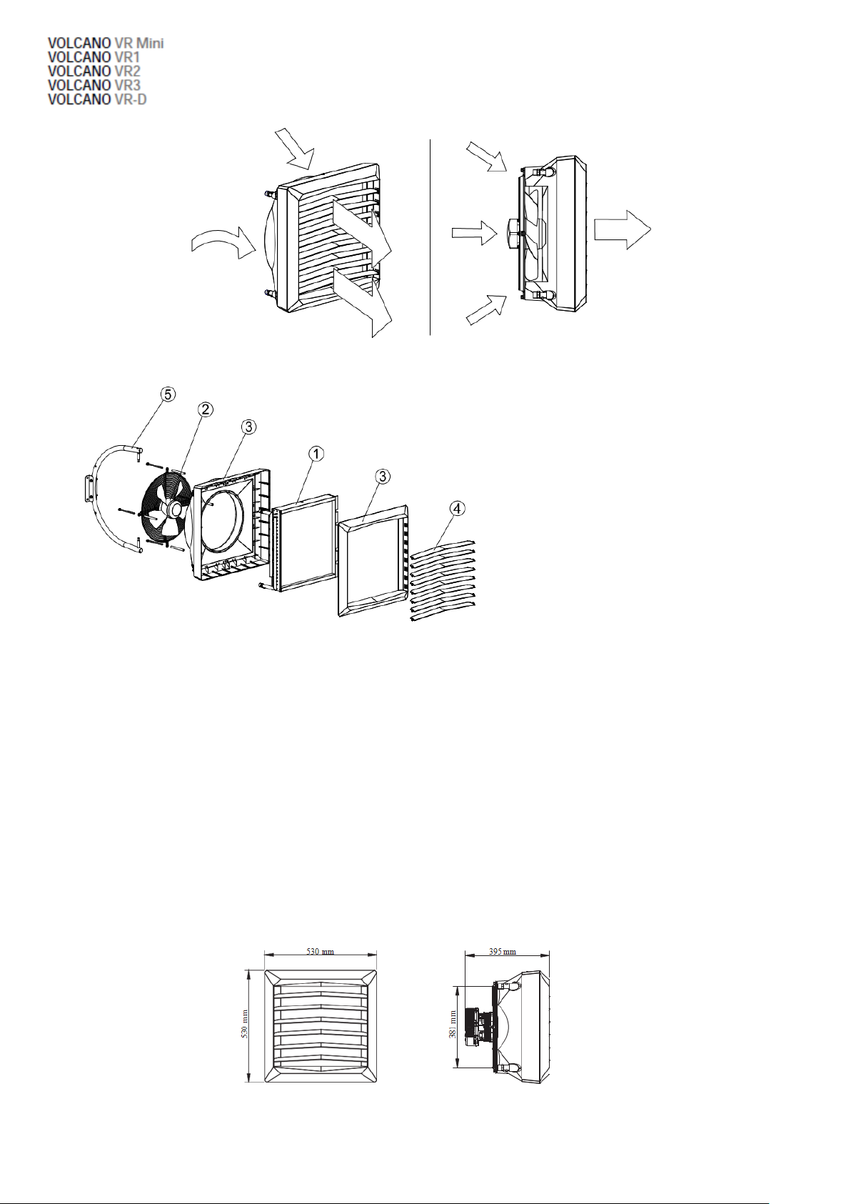
1. HEAT EXCHANGER;
2. AXIAL FAN;
3. COVER;
4. AIR GUIDES;
5. SAMPLE CONSOLE
2.3 DEVICE STRUCTURE (VOLCANO)
1. HEAT EXCHANGER: maximum parameters of a heating medium for a heat exchanger are: 266°F, 232PSI. Aluminium and copper construction
using copper tubes, coil pipe and aluminium lamellas. Connecting ferrules (male thread ¾”) are on the back panel of the unit. Our series of types
includes a single-row heat exchanger in VOLCANO VR1 17-102 MBH and two-row heat exchanger in VOLCANO VR Mini 10-68 MBH and VOLCANO
VR2 27-170 MBH and in VOLCANO VR3 44-256 MBH - three-row heat exchanger.
2. AXIAL FLOW FAN: maximum working temperature is 140°F, nominal power supply voltage is 120/60Hz or 240V/50Hz. EC Engine protection is
IP44, insulation class F. Air feed is performed by the axial flow fan, which is secured with a protective grate. Adequate blade profile and proper
bearings guarantee silent and unfailing operation of the device. High engine power allows for achieving high efficiency at low power
consumption rates, maintaining full air feed regulation. Properly profiled housing lowers the noise emission levels, which makes the device
particularly user-friendly, suitable for buildings with higher acoustic requirements.
3. HOUSING: consists of the body and the front panel, made of high quality plastic guaranteeing compatibility with devices powered by heating
medium with temperature parameter up to 266°F. Colorful side panels allow for matching the device color to the interior décor. Volcano VR-D
operates circulation air, improving its distribution and performing the de-stratification function.
4. AIR GUIDES: allow the hot air stream to be directed in 4 directions. Optimum air stream range and direction are achieved through the special
fan blade profile.
5. ASSEMBLY CONSOLE: an element of additional equipment - its ergonomic, light structure allows for rotating the device on the horizontal plane
for -140°÷0÷140°, to direct the stream of hot air wherever it is necessary.
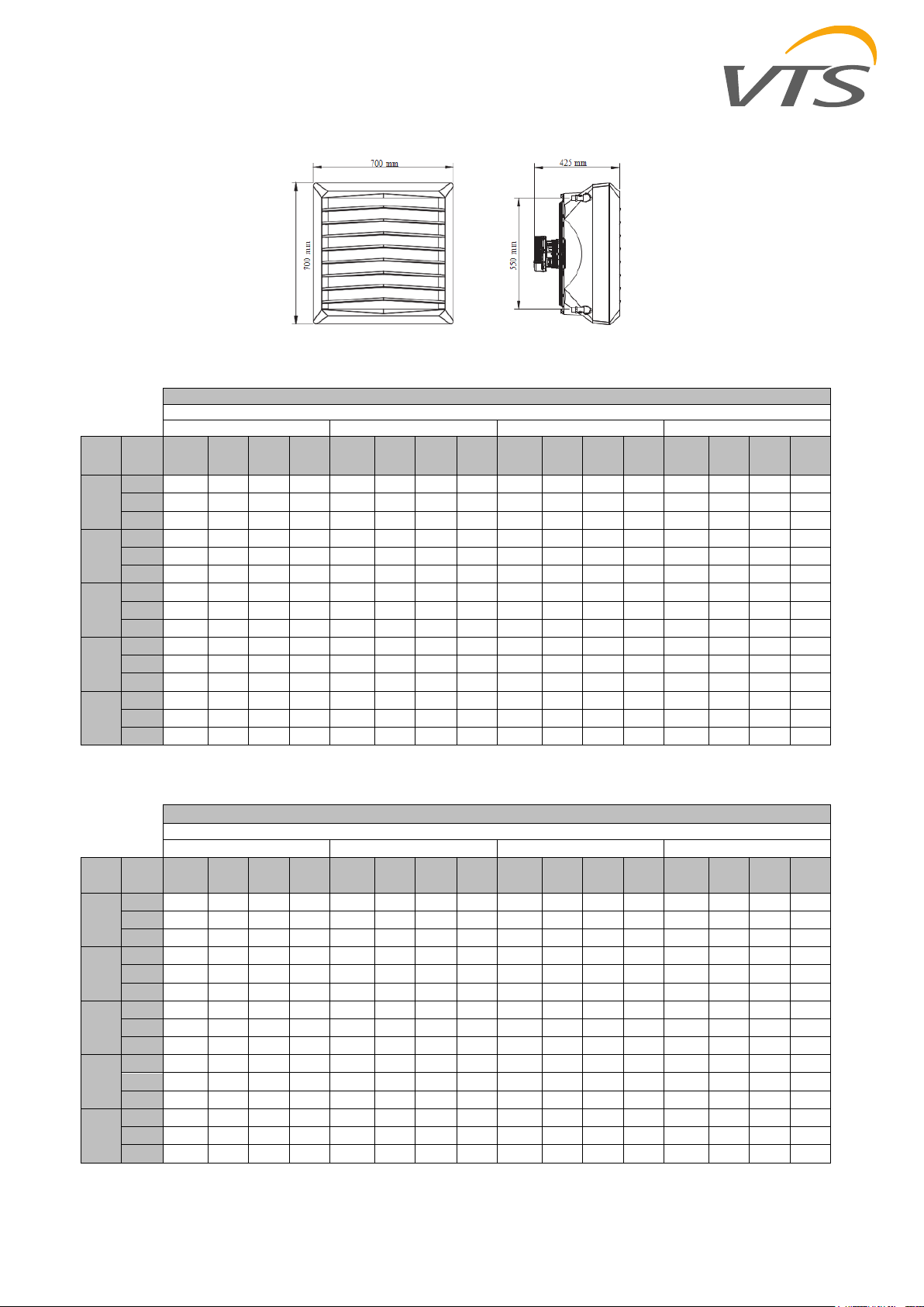
2.4 OVERALL DIMENSIONS
VOLCANO VR Mini
4
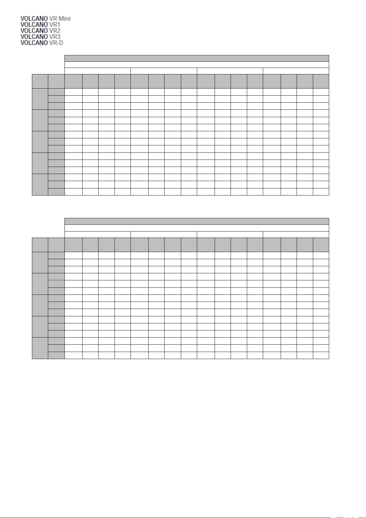
Volcano VR mini
Parameters Tz /Tp [°F]
194/158
176/140
158/122
122/86
Tp1
[°F]
Qp
[CFM]
Pg
[MBH]
Tp2
[°F]
Qw
[CFM]
Δp
[psi]
Pg
[MBH]
Tp2
[°F]
Qw
[CFM]
Δp
[psi]
Pg
[MBH]
Tp2
[°F]
Qw
[CFM]
Δp
[psi]
Pg
[MBH]
Tp2
[°F]
Qw
[CFM]
Δp
[psi]
32
1236
70,6
85,1
0,54
2,0
61,1
77,7
0,46
1,6
51,5
70,5
0,39
1,1
31,4
55,6
0,24
0,5
971
61,8
90,7
0,47
1,6
53,2
82,8
0,41
1,2
44,7
74,7
0,34
0,9
27,3
58,3
0,21
0,4
647
48,1
100,9
0,37
1,0
41,6
91,8
0,32
0,8
35,1
82,2
0,26
0,6
21,5
63,0
0,16
0,2
41
971
57,7
96,1
0,44
1,4
56,6
83,5
0,43
1,3
46,7
76,1
0,35
1,0
25,9
61,0
0,20
0,4
1236
66,2
90,7
0,51
1,8
49,5
88,0
0,38
1,0
40,9
79,9
0,31
0,8
23,2
63,3
0,18
0,3
647
45,4
105,6
0,35
0,9
38,6
96,4
0,29
0,7
32,1
86,9
0,24
0,5
18,4
67,3
0,14
0,2
50
1236
61,8
96,3
0,47
1,6
52,2
89,1
0,39
1,2
42,3
81,7
0,32
0,8
21,8
66,4
0,16
0,2
971
53,9
95,9
0,41
1,2
45,4
93,4
0,35
0,9
36,9
85,1
0,28
0,6
19,1
68,2
0,14
0,2
647
42,3
110,3
0,32
0,8
35,5
100,9
0,27
0,6
29,0
91,4
0,22
0,4
15,0
71,4
0,11
0,1
59
1236
57,3
101,8
0,44
1,4
47,4
94,6
0,36
1,0
37,5
87,3
0,28
0,6
16,7
71,6
0,13
0,2
971
49,8
106,5
0,38
1,1
41,3
98,6
0,32
0,8
32,8
90,3
0,25
0,5
14,7
73,0
0,11
0,1
647
39,2
115,0
0,30
0,7
32,4
105,6
0,25
0,5
25,9
95,9
0,19
0,3
11,3
75,4
0,09
0,1
68
1236
52,9
107,4
0,41
1,2
43,0
100,2
0,33
0,8
33,1
92,7
0,25
0,5
11,3
76,5
0,08
0,1
971
46,1
111,7
0,35
0,9
37,5
103,6
0,28
0,6
28,7
95,4
0,22
0,4
9,6
77,2
0,07
0,1
647
36,2
119,5
0,28
0,6
29,3
110,1
0,22
0,4
22,5
100,4
0,17
0,3
6,5
77,4
0,05
0,03
Volcano VR1
Parameters Tz /Tp [°F]
194/158
176/140
158/122
122/86
Tp1
[°F]
Qp
[CFM]
Pg
[MBH]
Tp2
[°F]
Qw
[CFM]
Δp
[psi]
Pg
[MBH]
Tp2
[°F]
Qw
[CFM]
Δp
[psi]
Pg
[MBH]
Tp2
[°F]
Qw
[CFM]
Δp
[psi]
Pg
[MBH]
Tp2
[°F]
Qw
[CFM]
Δp
[psi]
32
3119
102,0
62,2
0,78
3,8
88,0
58,1
0,67
2,9
74,0
54,0
0,56
2,1
45,0
45,5
0,34
0,9
2295
86,7
66,9
0,66
2,8
74,7
62,1
0,57
2,1
62,8
57,4
0,48
1,6
38,6
47,5
0,29
0,7
1648
72,3
72,7
0,55
2,0
62,4
67,1
0,48
1,5
52,5
61,5
0,40
1,1
32,1
50,2
0,24
0,5
41
3119
95,5
69,4
0,73
3,3
81,6
65,1
0,62
2,5
67,2
61,0
0,51
1,8
38,6
52,3
0,29
0,7
2295
81,2
73,8
0,62
2,5
69,3
68,9
0,53
1,9
57,3
64,0
0,44
1,3
32,8
54,1
0,25
0,5
1648
67,9
79,2
0,52
1,8
57,7
73,6
0,44
1,3
47,8
67,8
0,36
1,0
27,3
56,5
0,21
0,4
50
3119
89,1
76,5
0,68
2,9
75,1
72,3
0,57
2,1
60,7
68,0
0,46
1,5
31,4
59,4
0,24
0,5
2295
75,7
80,6
0,58
2,2
63,8
75,7
0,48
1,6
51,5
70,9
0,39
1,1
27,0
60,8
0,20
0,3
1648
63,1
85,5
0,48
1,5
53,2
79,9
0,41
1,1
43,3
74,3
0,33
0,8
22,5
62,6
0,17
0,3
59
3119
82,6
83,5
0,63
2,5
68,2
79,3
0,52
1,8
53,9
75,0
0,41
1,2
24,6
66,2
0,18
0,3
2295
69,9
87,3
0,54
1,9
58,0
82,4
0,44
1,3
46,1
77,5
0,35
0,9
20,8
67,5
0,16
0,2
1648
58,7
91,9
0,45
1,3
48,5
86,4
0,37
1,0
38,6
80,6
0,29
0,6
17,4
68,7
0,13
0,2
68
3119
75,7
90,5
0,58
2,2
61,8
86,4
0,47
1,5
47,1
82,0
0,36
0,9
17,1
73,0
0,13
0,2
2295
64,5
94,1
0,49
1,6
52,5
89,2
0,40
1,1
40,3
84,2
0,31
0,7
14,3
73,8
0,11
0,1
1648
53,9
98,2
0,41
1,1
44,0
92,7
0,34
0,8
33,8
86,9
0,25
0,5
11,9
74,7
0,09
0,09
VNO VR1, VR2, VR3, VR-D
3. TECHNICAL DATA
Tz – inlet water temperature; Tp – outlet water temperature; T
pressure drop in the heat exchanger
– inlet air temperature; T
p1
– outlet air temperature; Pg – heating capacity; Qw – water flow; Qp- air flow rate; Δp –
p2
Tz – inlet water temperature; Tp – outlet water temperature; T
pressure drop in the heat exchanger
– inlet air temperature; T
p1
– outlet air temperature; Pg – heating capacity; Qw – water flow; Qp- air flow rate; Δp –
p2
Volcano VR2
Parameters Tz /Tp [°F]
194/158
176/140
158/122
122/86
Tp1
[°F]
Qp
[CFM]
Pg
[MBH]
Tp2
[°F]
Qw
[CFM]
Δp
[psi]
Pg
[MBH]
Tp2
[°F]
Qw
[CFM]
Δp
[psi]
Pg
[MBH]
Tp2
[°F]
Qw
[CFM]
Δp
[psi]
Pg
[MBH]
Tp2
[°F]
Qw
[CFM]
Δp
[psi]
32
2855
170,9
87,3
1,30
3,5
147,1
79,7
1,12
2,7
123,5
72,1
0,94
2,0
76,1
56,7
0,57
0,8
2119
143,0
94,5
1,09
2,5
124,5
86,0
0,94
1,9
104,1
77,5
0,79
1,4
64,1
60,1
0,48
0,6
1413
111,6
105,1
0,85
1,6
96,6
95,4
0,74
1,2
81,6
85,5
0,62
0,9
50,5
65,1
0,38
0,4
41
2855
159,3
92,7
1,22
3,1
136,1
85,1
1,04
2,3
112,9
77,5
0,85
1,7
64,8
62,1
0,49
0,6
2119
134,1
99,5
1,02
2,2
114,6
91,0
0,87
1,7
95,2
82,6
0,72
1,2
54,9
64,9
0,41
0,4
1413
104,4
109,6
0,80
1,4
89,4
99,7
0,68
1,1
74,4
89,8
0,57
0,8
43,0
69,3
0,32
0,3
50
2855
148,8
98,2
1,14
2,7
125,2
90,7
0,95
2,0
101,7
83,1
0,77
1,4
53,2
67,3
0,40
0,4
2119
124,9
104,7
0,95
1,9
105,4
96,1
0,80
1,4
86,0
87,6
0,65
1,0
45,0
69,8
0,34
0,3
1413
97,6
113,9
0,75
1,2
82,6
104,0
0,63
0,9
67,2
94,1
0,51
0,6
35,5
73,2
0,26
0,2
59
2855
137,9
103,6
1,05
2,3
114,3
96,1
0,87
1,7
90,8
88,3
0,69
1,1
41,6
72,5
0,31
0,3
2119
116,0
109,6
0,89
1,7
96,2
101,1
0,74
1,2
76,4
92,5
0,58
0,8
35,1
74,3
0,26
0,2
1413
90,4
118,4
0,69
1,1
75,4
108,5
0,58
0,8
60,1
98,4
0,45
0,5
27,3
77,0
0,21
0,1
68
2855
126,9
109,0
0,97
2,0
103,4
101,5
0,79
1,4
79,5
93,7
0,60
0,9
28,7
77,4
0,22
0,1
2119
106,8
114,6
0,82
1,5
87,0
106,0
0,67
1,0
67,2
97,3
0,51
0,6
23,9
78,4
0,18
0,1
1413
83,6
122,7
0,64
0,9
68,2
112,6
0,52
0,6
52,9
102,6
0,40
0,4
18,1
79,9
0,14
0,06
Volcano VR3
Parameters Tz /Tp [°F]
194/158
176/140
158/122
122/86
Tp1
[°F]
Qp
[CFM]
Pg
[MBH]
Tp2
[°F]
Qw
[CFM]
Δp
[psi]
Pg
[MBH]
Tp2
[°F]
Qw
[CFM]
Δp
[psi]
Pg
[MBH]
Tp2
[°F]
Qw
[CFM]
Δp
[psi]
Pg
[MBH]
Tp2
[°F]
Qw
[CFM]
Δp
[psi]
32
3355
256,3
102,2
1,95
4,7
220,1
92,8
1,68
3,6
185,3
83,1
1,41
2,7
114,6
63,7
0,86
1,1
2413
206,8
111,4
1,58
3,2
179,1
100,8
1,37
2,5
151,2
90,0
1,15
1,8
93,8
68,0
0,71
0,8
1766
168,9
120,6
1,29
2,2
146,4
108,9
1,11
1,7
123,9
97,0
0,94
1,2
77,1
72,5
0,58
0,5
41
3355
238,5
106,9
1,82
4,2
204,0
97,3
1,55
3,1
169,2
87,8
1,28
2,2
97,9
68,0
0,74
0,8
2413
193,8
115,3
1,48
2,8
166,2
104,7
1,27
2,1
138,2
93,9
1,05
1,5
80,2
71,8
0,60
0,6
1766
158,3
124,0
1,21
1,9
135,8
112,3
1,04
1,5
112,9
100,2
0,86
1,1
65,9
75,6
0,49
0,4
50
3355
222,5
111,4
1,70
3,7
187,7
101,8
1,43
2,7
152,9
92,1
1,16
1,9
80,9
72,3
0,61
0,6
2413
180,8
119,5
1,38
2,5
153,2
108,7
1,17
1,8
124,9
97,9
0,95
1,3
66,2
75,4
0,49
0,4
1766
147,7
127,6
1,13
1,7
125,2
115,7
0,95
1,3
102,4
103,6
0,78
0,9
54,3
78,4
0,41
0,3
59
3355
206,1
115,9
1,58
3,2
171,3
106,3
1,31
2,3
136,5
96,6
1,04
1,5
62,8
76,3
0,47
0,4
2413
167,9
123,4
1,28
2,2
139,9
112,6
1,07
1,6
111,6
101,8
0,85
1,0
51,5
78,8
0,39
0,3
1766
137,2
131,0
1,05
1,5
114,6
119,1
0,87
1,1
91,4
106,9
0,69
0,7
42,3
81,1
0,32
0,2
68
3355
189,7
120,4
1,45
2,7
154,9
110,8
1,18
1,9
119,4
100,9
9,06
1,2
43,7
80,1
0,33
0,2
2413
154,6
127,4
1,18
1,9
126,6
116,6
0,97
1,3
97,9
105,6
0,74
0,8
35,5
81,5
0,26
0,1
1766
126,6
134,4
0,97
1,3
103,7
122,4
0,79
0,9
80,5
110,1
0,61
0,6
28,3
82,8
0,21
0,09
Tz – inlet water temperature; Tp – outlet water temperature; T
pressure drop in the heat exchanger
Tz – inlet water temperature; Tp – outlet water temperature; T
pressure drop in the heat exchanger
– inlet air temperature; T
p1
– inlet air temperature; T
p1
– outlet air temperature; Pg – heating capacity; Qw – water flow; Qp- air flow rate; Δp –
p2
– outlet air temperature; Pg – heating capacity; Qw – water flow; Qp- air flow rate; Δp –
p2
6

Parameter
Unit of
measure
VOLCANO
VR mini
VOLCANO
VR1
VOLCANO
VR2
VOLCANO
VR3
VOLCANO
VR-D
Number of rows in the heater
2 1 2 3
---
Maximum air fl ow rate
CFM
1236
3119
2855
3355
3826
Heating power range
MBH
10-68
17-102
27-171
44-256
---
Maximum temperature of the heating agent
°F
266
---
Maximum operating pressure*
psi
232
---
Maximum horizontal air stream range
ft
46
75
72
82
92
Maximum vertical air stream range
ft
26
39
36
39
49
Water capacity
in³
68
76
131
188
---
Connection diameter " 3/4
---
Weight of the device (without water)
lb
39
61
64
68
49
Power supply voltage
V/Hz
1 ~ 115/60 / 1 ~ 240/60
EC Motor rated power
HP
0,13
0,34
0,50
EC Motor rated current
A
0,51
1,3
1,7
EC Motor speed
rpm
1450
1430
1400
EC Motor IP
---
44
Volcano VR Mini
fan speed
III
II
I
air flow
CFM
1236
971
647
noise level for Volcano EC*
dB(A)
50
40
27
EC motor electric power**
HP
0,12
0,07
0,05
horizontal air stream range
ft
46
26
16
vertical air stream range
ft
26
16
10
Volcano VR1
fan speed
III
II
I
air flow
CFM
3119
2295
1648
noise level for Volcano EC*
dB(A)
54
49
38
EC motor electric power**
HP
0,33
0,25
0,21
horizontal air stream range
ft
75
66
49
vertical air stream range
ft
39
30
23
Volcano VR2
fan speed
III
II
I
air flow
CFM
2855
2119
1413
noise level for Volcano EC*
dB(A)
54
49
38
EC motor electric power**
HP
0,33
0,25
0,21
horizontal air stream range
ft
72
62
46
vertical air stream range
ft
36
26
20
NOTE Data concerning VOLCANO working parameters for a heating agent with a different temperature can be provided upon request
* reference conditions: room volume 52 972 ft³, measurement taken at a distance of 16ft
** EC motor electric power for the air flow mentioned in the table
* reference conditions: room volume 52 972 ft³, measurement taken at a distance of 16ft
** EC motor electric power for the air flow mentioned in the table
* reference conditions: room volume 52 972 ft³, measurement taken at a distance of 16ft
** EC motor electric power for the air flow mentioned in the table

* for vertical air guides adjustment
Volcano VR3
fan speed
III
II
I
air flow
CFM
3355
2413
1766
noise level for Volcano EC*
dB(A)
55
49
43
EC motor electric power**
HP
0,48
0,37
0,28
horizontal air stream range
ft
82
72
56
vertical air stream range
ft
39
30
23
Volcano VR-D
fan speed
III
II
I
air flow
CFM
3826
2707
2001
noise level for Volcano EC*
dB(A)
56
50
43
EC motor electric power**
HP
0,48
0,37
0,28
horizontal air stream range
ft
92
79
62
vertical air stream range
ft
49
36
30
* for vertical air guides adjustment
OPT. 6,5 - 16ft (Volcano VR Mini)
OPT. 8,2 – 26ft (Volcano VR1, VR2, VR3)
* reference conditions: room volume 52 972 ft³, measurement taken at a distance of 16ft
** EC motor electric power for the air flow mentioned in the table
* reference conditions: room volume 52 972 ft³, measurement taken at a distance of 16ft
** EC motor electric power for the air flow mentioned in the table
4. ASSEMBLY
NOTE Installation location should be suitably selected with special consideration of potential loads and vibrations.
Prior to any installation or maintenance works, disconnect the device from the power supply and secure it against accidental power-up.
Use filters in the hydraulic system. Before you connect the hydraulic lines (especially supply lines) to the device, you shou ld clean/rinse the
installation by draining two litres out of it.
NOTE It is necessary to maintain a minimum distance of 0.4m from the wall or the ceiling; otherwise the device can malfunction, the fan can be
damaged or its operating noise can increase.
If the device will be installed on a wall or under a ceiling, observe the following factors:
mounting heigh
distance between units – recommended distance 19,6-39ft (Volcano VR1, VR2, VR3), 9,8-23ft (Volcano VR Mini), in order to ensure even hot air
diffusion
8

* for horizontal air guide adjustment
** for symmetric air guide adjustment at an angle of 45°
range of air stream
device noise level (depending on acoustic characteristics of a room)
operation mode of the heating device, e.g. it can also operate as an air mixing device preventing air stratification
direction of air distribution should be controlled in a way that prevents draughts. Air stream must not be directed at walls, brackets, girders, cranes, shelves, machines, etc.
Examples of arrangement of air heating units mounted on a wall
4.1 INSTALLATION WITH A BRACKET
Each unit is supplied with bracket. In order to attach a bracket to the device, use crown drill bits to drill holes in the top and bottom panels of the heating unit (in places marked
with arrows), and insert sleeves (6) into the holes. Slide holder arms onto the sleeves. Insert M10x80mm screws (4) into the top and bottom sleeves, and fix the bracket position in
relation to the heater while tightening the screws. When you adjust the device in the right position, fit plugs onto the bracket.
The bracket unit consists of:
1. ARM (1 piece); 2. HOLDER; 3. M8x60mm SCREW WITH A WASHER AND NUT FASTENING THE CLAMP (2 sets); 4. M8x60mm SCREW FASTENING
THE HOLDER TO THE UNIT HEATER (2 pieces); 5. PLUG (2 pieces); 6. MOUNTING SLEEVE (2 pieces)

rotation of the device when mounted on a console
4.2 INSTALLATION INSTRUCTIONS AND MOUNTING DISTANCES
Installation of the heating medium supply system While installing the piping for the heating medium, secure the exchanger connection against
twisting 1. The piping should not overload the heater connections. It is possible to connect the piping with flexible connections (adjustable
angle of the airflow).
EXAMPLE OF A HYDRAULIC SYSTEM:
1. UNIT HEATER; 2. POWER-OPERATED VALVE; 3. VENT VALVE; 4. CUT-OFF VALVE; 5. FILTER; 6. CIRCULATION PUMP; 7. BOILER
10

Heater vent/ heating medium drain
The device will be vented when you loosen the vent bolt 1 placed on the connection pipe. The heating medium is drained through the drain plug
2, placed on the bottom connection pipe. When starting the device after the heating agent has been drained, remember to vent the heater.
You need to pay special attention to secure the device against water accidentally getting into the heater casing during the agent draining
process.
Connecting to the power supply
NOTICE The installation must be equipped with disconnectors at all power supply poles. Recommended safety: overload disconnector VOLCANO
VR Mini – 1 A, VOLCANO VR1, VR2 – 2 A, VOLCANO VR3, VR-D - 4A) and differential current safety. VOLCANO VR Mini, VR1, VR2, VR3, VR-D
(fan) are equipped with a terminal block accepting 7 x 14 AWG electric wires. NOTICE We recommend connecting the wires to the terminal
block with pre-installed bushings.
Adjusting the air guides
Volcano air guides are mounted on the pivot (1), which provides smoothly change of air direction. In order to change position of air blade should
turn it in both hands (grasping the edges of the enclosure) to turn the blade at the same time on both pins.
VOLCANO VR Mini, VR1, VR2, VR3, VR-D

MODEL
DIAGRAM
TECHNICAL DATA
COMMENTS
WALL-MOUNTED CONTROL
PANEL
HMI-WING EC
•
Device operation: Capacitive touch buttons
•
Power supply: 230 V AC
•
Temperature measurement: 14 °F ... 210 °F ; NTC10K
•
Outputs:
- 1 analog output 0-10V (8 bit, Imax = 20 mA)
- 2 relays outputs (250 VAC, AC1 500 VA dla 230 VAC)
•
Inputs: 1 digital input type “dry contact”, Imax = 20 mA
•
Communication: Modbus RTU
•
Parameters of working environment: temperature:
32 - 140 °F, humidity: 10 - 90%, without
condensation
•
used for control all types of WING EC curtains
•
touch control panel
•
the main on / off switch (ON / OFF)
•
three-stage adjustable fan speed of the EC motor
•
built-in thermostat with possibility weekly programing
•
continuous mode
•
function of heating and ventilation
•
door sensor operation
•
two-stage adjustable of heating power
•
RS 485 with ModbusRTU
•
Suggested cross sections of electrical cables::
- L, N : 0.08x0.04 in2
- H1, H2 : 0.08x0.04 in2
- AO, GND : 0.08x0.02 in2 LIYCY
- Door sensor : 0.08x0.02 in2 LIYCY
- RS 485 : 0.12x0.03 in2 LIYCY
TWO-WAY VALVE WITH ACTUATOR
TWO-WAY VALVE
● Terminal diameter: 3/4”
● Mode of operation: two-way ON/OFF
● Maximum differential pressure: 13psi
● Pressure class: PN 16
● Kvs flow ratio: 2.65 CFM
● Maximum temperature of heating medium: 221°F
● Parameters of working environment: from 32 to 140°F
VALVE ACTUATOR
● Power consumption: 7 VA
● Supply voltage: 230VAC +/-10%
● Closing/opening time: 4-5/9-11 s
● Position without power: closed
● Level of protection: IP54
● Parameters of working environment: from 89 to 284°F
● It is recommended to install a two-way valve on the return pipeline.
● The drawings with the elements of automatics contain only visualizations of
sample products.
● It is recommended to connect the supply, using a conductor of the min. size
0.08x0.03 in2.
● The drawings with the elements of automatics contain only visualizations of
sample products.
5. AUTOMATICS
5.1 ELEMENTS OF AUTOMATICS
Electric connections may only be made by well-trained electricians, and according to:
Occupational health and safety regulations
Assembly instructions
Technical documentation for each of the automatic elements
NOTE Before starting the assembly process and connecting the system, familiarize yourself with the original documentation attached to the
automatic devices.
6. START-UP, OPERATION, MAINTENANCE
6.1 START-UP/PUTTING INTO OPERATION
Prior to any installation or maintenance works, disconnect the device from the power supply and secure it against accidental power-up.
Use filters in the hydraulic system. Before you connect the hydraulic lines (especially supply lines) to the device, you shou ld clean/rinse
the installation by draining a few litres out of it.
Install vent valves at the highest point of the installation.
Install cut-off valves directly behind the device, so it can be easily disassembled.
Secure the device against pressure increase according to the permitted maximum pressure value of 232psi.
Hydraulic pipes need to be free from any stresses and loads.
Prior to the first start-up of the heater, check the hydraulic connections (vent and collector air-tightness, installed fittings).
Prior to the first start-up of the heater, check the electric connections (connection of automatic devices, power supply, fan).
It is suggested to use additional external current differential protection.
6.2 OPERATION AND MAINTENANCE
Device casing does not require any maintenance.
Heat exchanger needs to be regularly cleaned of dirt and grease. Especially before the heating season, the heat exchanger needs to be
cleaned with the use of compressed air on the side of the air guides (but the device does not need to be disassembled). Pay attention
to the exchanger’s lamellas, as these are delicate.
If lamellas bend, straighten them with a special tool.
The fan motor does not require any maintenance. It may only require cleaning of the protective mesh, fan blades and dust and grease
deposits.
If the device is not used for a long time, disconnect the voltage supply.
Heat exchanger does not have fire protection.
It is recommended to periodically blow through the heat exchanger, preferably with compressed air.
The heat exchanger can freeze (fracture) when the room temperature falls below 0°C and the heating agent temperature decreases at
the same time.
The level of air pollutants should meet the criteria allowable concentrations of pollutants in indoor air, for non-industrial areas, the level
of dust concentration up to 0.3 g / m³. It is forbidden to use device for the duration of the construction works except for the start-up of
the system.
The equipment must be operated in rooms used throughout the year, and in which there is no condensation (large fluctuations in
temperature, especially below the dew point of the moisture content).
The device should not be exposed to direct UV rays.
The device should be operated at the supply water temperature up to 266 °F with working fan.
12

VR Mini, VR1, VR2, VR3, VR-D
Problem
Check points
Description
Heat exchanger leaking
● assembly of the exchanger connections with two wrenches
(adjustment), which safeguards against internal twisting of the
collectors,
● Check if the leakage may be associated with mechanical damage to
the exchanger,
● Vent valve or drain plug leaking,
● Heating agent parameters (pressure and temperature) – should not
exceed permitted values,
● type of heating agent (it cannot be aggressive to Al and Cu),
● Circumstances when the leakage appears (e.g. during the first,
tentative installation start-up, when the installation is filled up after
the heating agent has been drained) and outside temperature at
the time of failure (risk that the exchanger may freeze),
● Possibility of operating in aggressive conditions (e.g. high
concentration of ammonia in the air in a sewage-treatment plant),
Pay special attention that the exchanger may freeze during winter time.
99% of registered leakages appear during installation start-up/ pressure
tests. The defect can be removed by pulling back vent or drain valve.
Fan works too loud
● check the device assembly for conformity with the instructions
in operation and maintenance manual (e.g. distance from
wall/ceiling),
min. 15 inches
● Device appropriately level led,
● Correctness of electric connections and qualifications of the
wireman,
● Inlet current parameters (e.g. voltage, frequency),
● noise at lower gears (possible controller failure?),
● Noise only at higher gears (regular situation explained by
aerodynamic characteristics of the device, if there outlet air
chokes),
● type of other devices operating in the building (e.g. induced draught
fans) – intensified noise caused by simultaneous operation of many
machines,
● Does the fan rub against the casing?
● Is the fan evenly screwed to the casing?
Level of operating noise of VOLCANO devices is perceived subjectively. If the
device is made of plastic, it should operate quietly. It is recommended to
unscrew the clamping screws and tightening them up again. If the fault does
not disappear, you should make a complaint.
Fan does not work
● Correctness and quality of electric connections and qualifications of
the wireman,
● Inlet current parameters (e.g. voltage, frequency) on the clamp
block of fan engine,
● Correctness of operation of other devices installed in the building,
● Correctness of wire connections on the engine side acc. to the
manual, in comparison to wires clamped in the engine terminal
strip,
● PE conductor voltage (if present, may mean there is a break-down),
● Is N conductor correctly connected to the fan.
Electrical connection need to be done strictly according to the
drawings in the manual.
Damaged casing
● Circumstances when it was damaged – notes on the bill of
ladings, stock issue confirmation, condition of the box,
If the casing is damaged, make photos of the box and device, and photos
confirming that the device serial number on the device and on the box
are the same. If the device was damaged during transport, it is necessary
to write down an appropriate statement by the driver, who delivered
the damaged device
Actuator does not open the
valve
● Correctness of electric connections and qualifications of the
wireman,
● Correctness of the thermostat operation (characteristic tick
sound during change- over),
● Inlet current parameters (e.g. voltage),
The most important is to check whether the actuator responded to the
electric impulse.
7. INDUSTRIAL SAFETY INSTRUCTION
Special instructions concerning safety NOTE
Prior to any work connected with the device, the device must be disconnected from the power supply and be secured properly.
Wait until the fan stops.
Use stable assembly platforms and hoists.
Depending on the heating agent temperature, piping, parts of the casing, heat exchanger surface can be very hot, even after t he fan
stops.
There may be some sharp edges! During transport, use protective gloves, protective clothing and safety shoes.
The health and safety instructions must be followed.
Loads can be fastened only in places designed for it in a transport unit. While devices are lifted by an assembly unit, their edges
need to be secured. Distribute the load evenly.
The device needs to be protected against moisture and dirt and should be stored in rooms secured against atmospheric
influences.
Disposal: Take care to dispose of used materials, packaging material and spare parts in a safe way, one which is not harmful to the
environment and is in accordance with local regulations.
8. SERVICING
8.1 PROCEDURES IN CASE OF DEFECTS

REMEMBER!
The user of equipment intended for households, and which has been worn out, is obliged to transfer such equipment to a collecting unit that
collects worn-out electric and electronic equipment. The selective collecting and further processing of waste from households contributes to the
protection of environment, reduces the penetration of hazardous substances into the atmosphere and surface waters.
8.2 COMPLAINT PROCEDURE
In order to report a problem with the device or elements of automation, please fill in and send the appropriate form, using one of the three
available ways:
1. E-mail: vts.pl@vtsgroup.com
2. Fax: (+48) 12 296 50 75
3. Website: www.vtsgroup.pl\PRODUKT\VTS Service\formularz zgłoszeniowy
Our service department will contact you immediately.
In the case of damage in transport, send a complaint notification, including the delivery documentation (bill of lading, inventory issue) and
photographs showing the defects. Should you have any questions, please contact us, using this telephone number: 0 801 080 073
IMPORTANT!
The complaint procedure shall be initiated when the Service Department has received a correctly filled complaint notification, a copy of
the purchase invoice and the Warranty Card, filled by the company that carried out the installation.
it is forbidden to place, dispose of and store worn-out electric and electronic equipment, together with other waste.
Dangerous compound contained in electronic and electric equipment have a very adverse impact on plants, microorganisms, and, most importantly, on humans, as they damage our central and peripheral nervous system, as well as
circulatory and internal system. Additionally, they cause serious allergic reactions. Worn-out equipment is to be delivered
to a local collection point for used electric equipment, which carries out a selective collection of waste.
14

9. ELECTRICAL DIAGRAMS
9.1. Connection of Volcano VR Mini, VR1, VR2, VR3, VR-D to the HMI VR controller
1-supply: 120V – 60Hz /240V - 60Hz*, 2-main switch, fuses*, 3-HMI VR controller, 4-Volcano fan
* the device does not include: the main switch, fuses and feeder cable
9.2. Connection of Volcano VR Mini, VR1, VR2, VR3 to the HMI VR controller and valve actuator
1-supply: 120V – 60Hz /240V - 60Hz *, 2-main switch, fuses*, 3-HMI VR controller, 4-Volcano fan, 5-valve with actuator
* the device does not include: the main switch, fuses and feeder cable

9.3. Connection of Volcano VR Mini, VR1, VR2, VR3 to the HMI VR controller and external temperature sensor
1-supply: 120V – 60Hz /240V - 60Hz *, 2-main switch, fuses*, 3-HMI VR controller, 4-Volcano fan
* the device does not include: the main switch, fuses and feeder cable
9.4. Connection of Volcano VR Mini, VR1, VR2, VR3 to the HMI VR controller, valve actuator and external temperature sensor
1-supply: 120V – 60Hz /240V - 60Hz *, 2-main switch, fuses*, 3-HMI VR controller, 4-Volcano fan, 5-valve with actuator
* the device does not include: the main switch, fuses and feeder cable
16

VTS POLSKA Sp. z o.o.
Al. Grunwaldzka 472 A
80-309 Gdańsk
Polska
www.vtsgroup.com
The company submitting the notification:
The company that installed the equipment:
Date of notification:
Type of device:
Factory number*:
Date of purchase:
Date of installation:
Place of installation:
Detailed description of defect:
Contact person:
Name and surname:
Telephone:
E-mail:
* This field must be filled, if the complaint notification refers to the following equipment: VOLCANO VR1 and VR2 unit, and WING air curtains.

1. Stamp of the company to carry out installation
VTS POLSKA Sp. z o.o.
Al. Grunwaldzka 472 A,
80-309 Gdańsk
Polska
www.vtsgroup.com
2. Factory number of device
3. Place of installation
4. Date of installation
5. Address, street
6. Apartment number
7. City
8. Postal code
Based on these Warranty Terms and Conditions, the company from the VTS Group (hereinafter: VTS) specified in the warranty card hereby guarantees to the owner (hereinafter: Customer) that
the Volcano VR, WING W100 - 200, WING E100 – 200, WING C100 - 200 devices (hereinafter: devices) sold by VTS will work without malfunctions.
are sent for repair.
the costs of transporting spare parts. The current list of VTS Licensed Service Centres, hereinafter service centres, is available on www.vtsgroup.com and in VTS business offices.
Operation & Maintenance Manual or by individuals without proper qualifications.
individuals without proper qualifications.
inspections or maintenance activities were conducted by individuals without proper qualifications.
the devices.
country of purchase, VTS is under no obligation to provide service under the warranty.
application specified above.
specified by VTS. The device serial number must be consistent with the number on the original packaging and in the Warranty Card.
service price list available on www.vtsgroup.com
install the devices,
service performance site meets the requirements defined in legal regulations.
service, the Customer has the right to complain to VTS. Provisions of § 4 hereof shall apply to such a complaint as appropriate.
shall prevail. In such an event, any contradictory provisions of the Proposal and the Purchase Order shall not apply.
prevail.
10. VTS STANDARD WARRANTY TERMS AND CONDITIONS FOR EUROHEAT PRODUCTS
Warranty card
18

INSPECTIONS AND MAINTENANCE
Date
Made by
Company
Cleaning, Cleaning of the heat exchanger
11. TABLE OF INSPECTION AND MAINTANANCE
 Loading...