

VTS Medical Systems VividImage MON-VTS42SDI-MT, VividImage MON-VTS42SDI-MD, VividImage MON-VTS52SDI-MD, VividImage MON-VTS52SDI-MT Operation Manual
MON-VTS42SDI-MD
VividImage
Medical Grade
High Definition Wide Screen Monitor
®
OPERATION MANUAL
MON-VTS42SDI-MD
MON-VTS42SDI-MT
MON-VTS52SDI-MD
MON-VTS52SDI-MT
Document # 82070-639, Revision C CONFIDENTIAL © 2009 Copyright VTS Medical Systems, LLC
1 of 29

Notice for Users
IMPORTANT:
To aid in reporting in the case of loss or theft, or for
service maintenance purposes, please record the
monitor’s model and serial numbers in the space
provided. The numbers are located on the rear of
the monitor.
FCC Statement
WARNING — FCC Regulations state that any unauthorized changes or modifications to this equipment not
expressly approved by the manufacturer could void the user’s authority to operate this equipment.
Note: This equipment has been tested and found to comply with the limits for a Class A digital device, pursuant to
Part 15 of the FCC Rules.
These limits are designed to provide reasonable protection against harmful interference when the equipment is
operated in a commercial environment. This equipment generates, uses, and can radiate radio frequency energy
and, if not installed and used in accordance with the instruction manual, may cause harmful interference to radio
communications. Operat ion of this equip ment in a reside ntia l area is likely to cause harmful interference in which
case the user will be required to correct the interference at his own expense.
Declaration of Conformity
MON-VTS42SDI-MD / MON-VTS52SDI-MD:
This device has been evaluated to the UL 60601-1 standard:
Equipment evaluated to this standard is not suitable for use in the presence of a flammable anesthetic mixture
with air or with oxygen or nitrous oxide (unless additional tests have been passed). Therefore this device is not
suitable for use in the presence of a flammable anesthetic mixture with air or with oxygen or nitrous oxide.
MON-VTS42SDI-MD / MON-VTS42SDI-MT / MON-VTS52SDI-MD / MON-VTS52SDI-MT:
This device complies with Part 15 of the FCC Rules. Operation is subject to the following two conditions: (1) this
device may not cause harmful interference, and (2) this device must accept any interference received, including
interference that may cause undesired operation.
Function, Intended Application and Mode of Operation:
The VividImage Series of monitors are intended to be used in the displaying and viewing of video and graphics for
review and analysis by trained medical practitioners. The mode of operation for this device is continuous
operation.
For a complete list of current certifications, please refer to the Specifications page of this manual.
Model No:
Serial No:
Document # 82070-637, Revision C CONFIDENTIAL © 2009 Copyright VTS Medical Systems, LLC
2 of 29

Table of Contents
Notice for Users ........................................................................................................................................................... 2
FCC Statement ......................................................................................................................................................... 2
Declaration of Conformity .......................................................................................................................................... 2
Tips and Safety Precautions ....................................................................................................................................... 5
Monitor and Accessory Checklist .............................................................................................................................. 5
Mounting ................................................................................................................................................................... 5
Location ..................................................................................................................................................................... 5
Power Cord ............................................................................................................................................................... 5
Manual Scope ........................................................................................................................................................... 5
Connecting and Powering On the Monitor................................................................................................................. 6
Unpacking the carton .................................................................................................................................................. 6
Figure 1: Included Cables ..................................................................................................................................... 6
Mounting the Monitor .................................................................................................................................................. 7
Figure 2: Mounting Holes ...................................................................................................................................... 7
Connecting the Video Inputs....................................................................................................................................... 7
Table 1: Inputs and Connections .......................................................................................................................... 7
Figure 3: Connecting the Power Cord ................................................................................................................... 7
Figure 4: VividImage Monitor Rear View .............................................................................................................. 8
Configuring Touch Capability ..................................................................................................................................... 8
Control Devices ............................................................................................................................................................ 9
Side Control Panel ....................................................................................................................................................... 9
Figure 5: The Side Control Panel, Table 2: Side Control Functions...................................................................... 9
Remote Control .......................................................................................................................................................... 10
Overview of Remote Control Functions ................................................................................................................... 10
Figure 6: The Remote Control, Table 3: Remote Control Functions ................................................................... 10
Changing the Remote Control Battery..................................................................................................................... 10
Figure 7: Changing the Remote Control Battery ................................................................................................. 10
On Screen Display (OSD) .......................................................................................................................................... 11
Navigating OSD Menus .............................................................................................................................................. 11
Figure 8: OSD Menu Layout ............................................................................................................................... 11
Details of OSD Menu Functions ................................................................................................................................ 12
Display Menu .......................................................................................................................................................... 12
Table 4: Display Menu Functions........................................................................................................................ 12
Image menu ............................................................................................................................................................ 13
Table 5: Image Menu Functions ......................................................................................................................... 13
Color menu .............................................................................................................................................................. 14
Table 6: Color Menu Functions ........................................................................................................................... 14
Advanced menu ...................................................................................................................................................... 15
Table 7: Advanced Menu Functions ................................................................................................................... 15
Table 8: OSD Menu Settings Functions .............................................................................................................. 16
Setup menu ............................................................................................................................................................. 17
Table 9: Setup Menu Functions .......................................................................................................................... 17
Document # 82070-637, Revision C CONFIDENTIAL © 2009 Copyright VTS Medical Systems, LLC
3 of 29

Locking the OSD ........................................................................................................................................................ 18
To Lock the OSD ..................................................................................................................................................... 18
Figure 9: Setup Menu ......................................................................................................................................... 18
Figure 10: Setup Menu, Lock Mode Selected ..................................................................................................... 18
Figure 11: Setup Menu, Lock Mode Selections .................................................................................................. 19
Figure 12: Display Menu ..................................................................................................................................... 19
Figure 13: Brightness Function Selections ......................................................................................................... 20
Figure 14: OSD Locked ...................................................................................................................................... 20
Temporarily Overriding the OSD Lock ..................................................................................................................... 20
Figure 15: OSD Unlocked ................................................................................................................................... 20
Adjusting Monitor Settings with Hot Key Controls ................................................................................................. 21
Input Source Selection .............................................................................................................................................. 21
Figure 16: Input Source Selections ..................................................................................................................... 21
Mode Item Selection .................................................................................................................................................. 22
Figure 17: Color Mode Selections....................................................................................................................... 22
Gamma Item Selection ............................................................................................................................................... 22
Figure 18: Gamma Value Selection .................................................................................................................... 22
Using Picture In Picture (PIP) and Picture And Picture (PAP) Modes .................................................................. 23
Selecting PIP and PAP modes ................................................................................................................................ 23
Primary Source and Secondary Source Selection .................................................................................................. 24
Table 10: PIP and PIP Function Availability for Signal Type Combinations ........................................................ 24
Monitor Care / Troubleshooting ................................................................................................................................ 25
Monitor Care ........................................................................................................................................................... 25
Troubleshooting ...................................................................................................................................................... 25
Specifications ............................................................................................................................................................. 26
Table 11: Specifications ...................................................................................................................................... 26
Glossary ...................................................................................................................................................................... 27
Index ............................................................................................................................................................................ 28
Document # 82070-637, Revision C CONFIDENTIAL © 2009 Copyright VTS Medical Systems, LLC
4 of 29

Tips and Safety Precautions
- Do not display a still image for ten (10) or more
hours. An afterimage may remain.
- It may be difficult to see the image on the
screen if the brightness is adjusted to the
minimum s etting.
- The quality of the video signal may influence the
quality of the displayed image.
- Do not open the monitor.
- When unpacking, carrying or mounting the
monitor at least two people are needed. Make
sure the monitor is in the upright position.
Monitor and Accessory Checklist
- Included in the carton are the following items:
1 VividImage HD Wide Screen Monitor
1 DVI Cable
1 VGA Cable
1 S-Video Cable
1 Power Cable
1 Remote
8 Mounting Screws (attached to the monitor)
1 Touch Setup CD (MON-VTS42-SDI-MT /
MON-VTS52SDI-MT only)
1 Quick Start Guide
Notes:
- Retain the carton and packing material for
storing or transporting the monitor.
Mounting
- Always follow mounting instru c tion s to avoid
physical injury and/or damage to the monitor .
Location
- Use the monitor in a suitable environment. See
“Operating Temperature” and “Storage
Temperature” on the Specifications page of this
manual.
- Use caution around liquids as you would with
any electrical appliance.
- Do not insert objects into the monitor.
- Do not place the monitor on unstable surfaces.
- In all cases, refer to the specifications in this
manual to ensure proper monitor performance.
Use of the monitor outside of operating
specifications will void the monitor warranty and
may cause permanent damage to the monitor.
Power Cord
- Do not damage the power cord. Damage to the
cord may result in fire or electric shock.
- Do not add extension cords.
- Use only the power cord included with the
monitor.
- Insert the power plug directly into the AC outlet.
- Do not remove or insert the power plug with wet
hands. Doing so could result in electric shock.
Manual Scope
- This manual is written for use with the MONVTS42SDI-MD /MON-VTS42SDI-MT/ MONVTS52SDI-MD/MON-VTS52SDI-MT. When
describing a different specifi ca tion between the
models, the model number is given. (When the
model number is not given, the description is
true for both models. For product appearance,
illustrations of model MON-VTS42HD-MD are
used in this manual.)
Document # 82070-637, Revision C CONFIDENTIAL © 2009 Copyright VTS Medical Systems, LLC
5 of 29
Connecting and Powering On the Monitor
1 VividImage HD Wide Screen Monitor
This section includes all the information you need to start using your new monitor.
Unpacking the carton
Included in the carton are the following items:
1 DVI cable
1 VGA cable
1 S-Video Cable
1 Power Cable
1 Remote
8 Mounting Screws (Attached to the monitor)
1 Touch Setup CD (MON-VTS42SDI-MT / MON-VTS52SDI-MT only)
1 Quick Start Guide
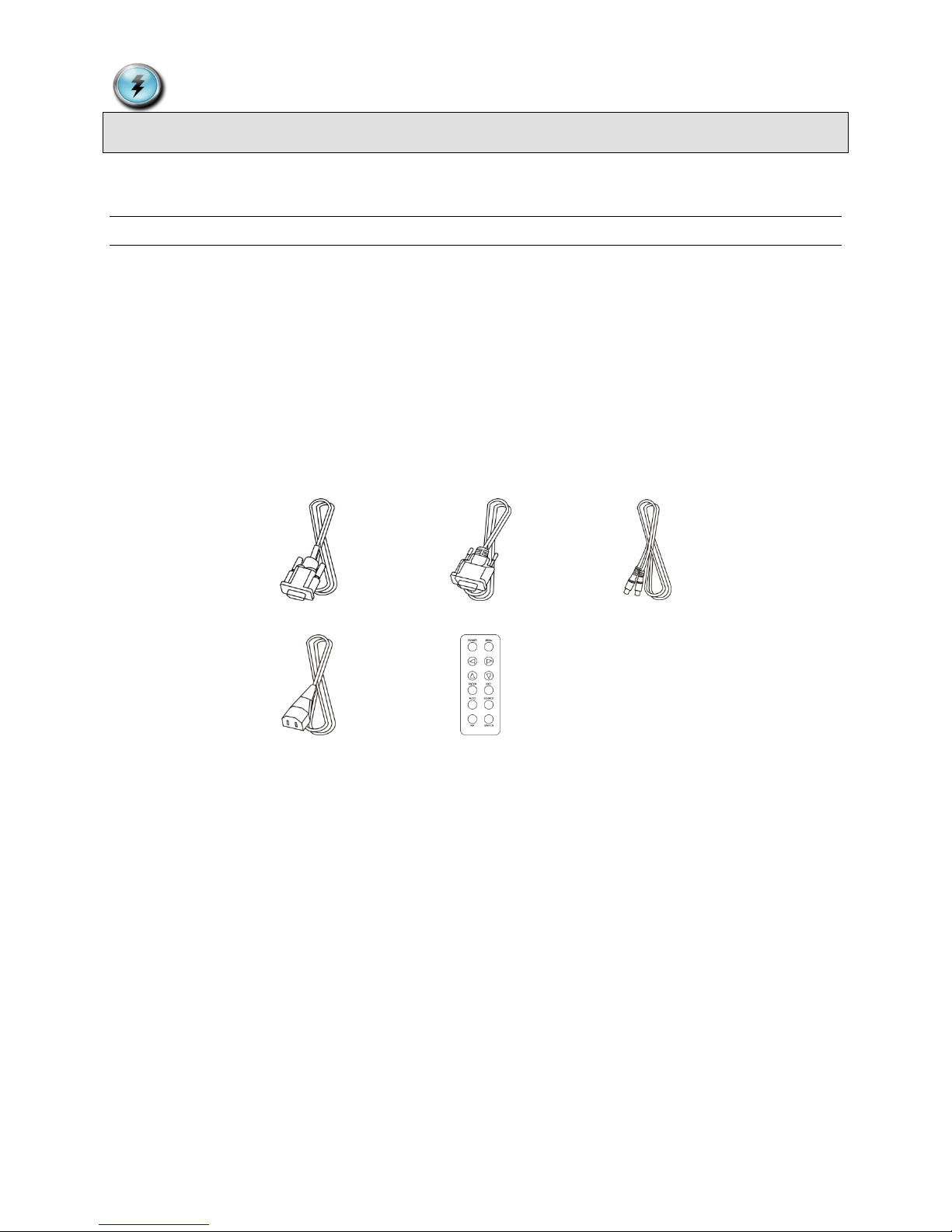
1 DVI Cable 1 VGA Cable 1 S-Video Cable
1 Power Cord 1 Remote Control
Figure 1: Included Cables
If any one of these items is missing, please call VTS Customer Support at (877) VTS-1788.
Document # 82070-637, Revision C CONFIDENTIAL © 2009 Copyright VTS Medical Systems, LLC
6 of 29
Mounting the Monitor
Y/Cb/Cr input
8pin Mini Din (x1)
S-Video input
4pin Mini Din (x1)
Video Input
RCA Jack (x1)
HD-SDI input (Option)
BNC Connector (x3)
RGBSync input (Option)
BNC Connector (x8)
RS-232 control (IN/OUT)
D-Sub 9 pin
USB Touch control( MON-VTS42SDI-MT / MON-VTS52SDI-MT only)
USB-A
RS-232 Serial Touch control (MON-VTS42SDI-MT / MON-VTS52SDI-MT only)
D-Sub 9 pin
AC Switch / Power cord input
AC Power Input
Eight mounting
These ports available on MON-VTS42SDI-MT /
MON-VTS52SDI-MT only
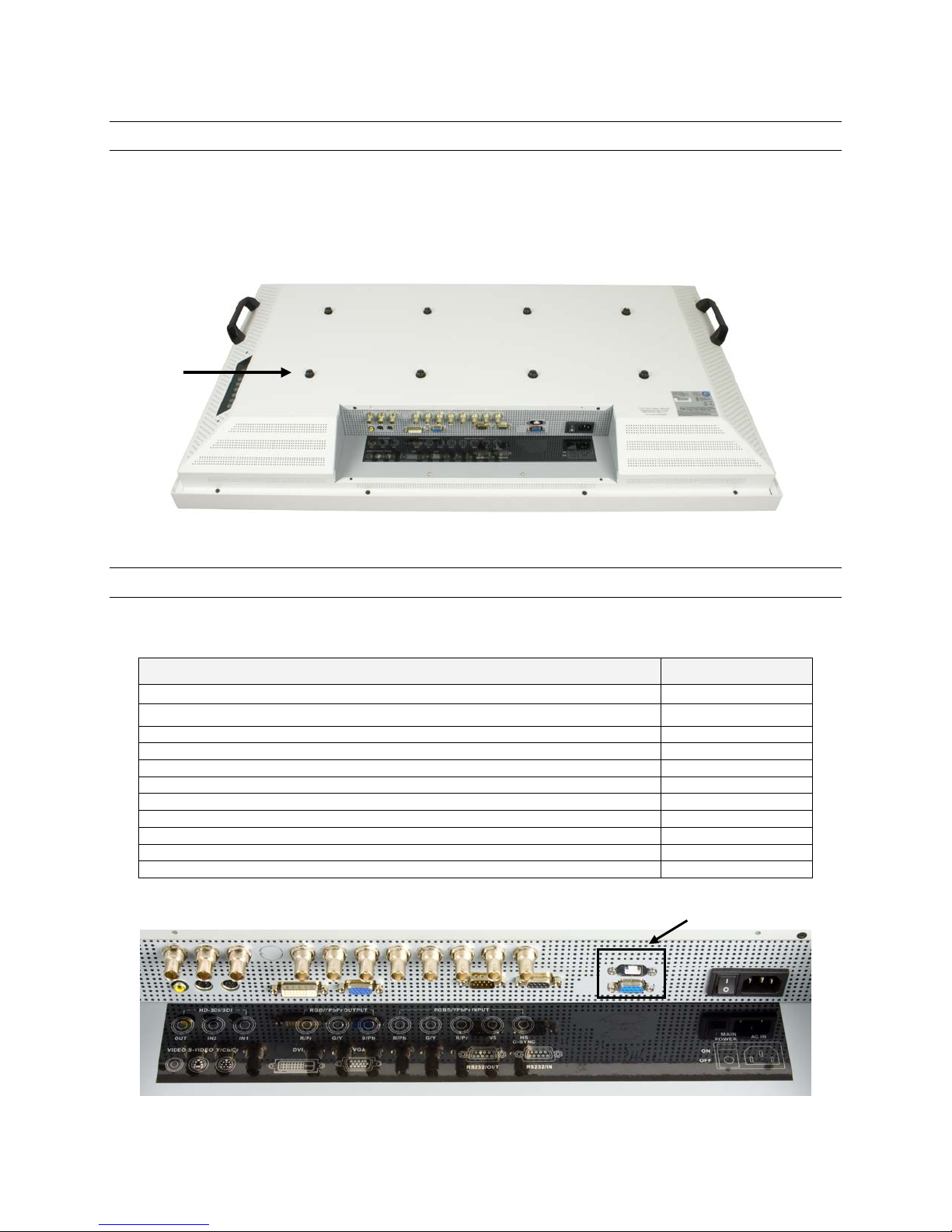
The monitor can be mounted using the eight included screws. The hole pattern for the eight screws neede d to mount
the monitor can be seen in the drawing below.
Unscrew the eight screws from the back cover. It is recommended that you use all eight screws when mounting the
monitor using a wall mount kit (not included). You must use at least four of the screws, either in the four center holes
or the four outer holes. Follow the directions that come with the wall mount kit to complete the installation.
holes and screws
Figure 2: Mounting Holes
Connecting the Video Inputs
The video input cable(s) should be attached to the appropriately labeled ports on the back of the monitor as shown
below. The following inputs are available:
Name Connection Type
VGA (RGB) input D-Sub 15pin (x1)
DVI input DVI-D (x1)
Table 1: Inputs and Connections
Figure 3: Connecting the Power Cord
Document # 82070-637, Revision C CONFIDENTIAL © 2009 Copyright VTS Medical Systems, LLC
7 of 29
Plug the appropriate end of the power cord into the 3-pronged interface on the back of the monitor. Plug the other
end of the power cord into an outlet and turn the main power switch to on.
Input: 100-240 Volts (V) ~ 3 Amperes (A) 50/60 Hertz (Hz)
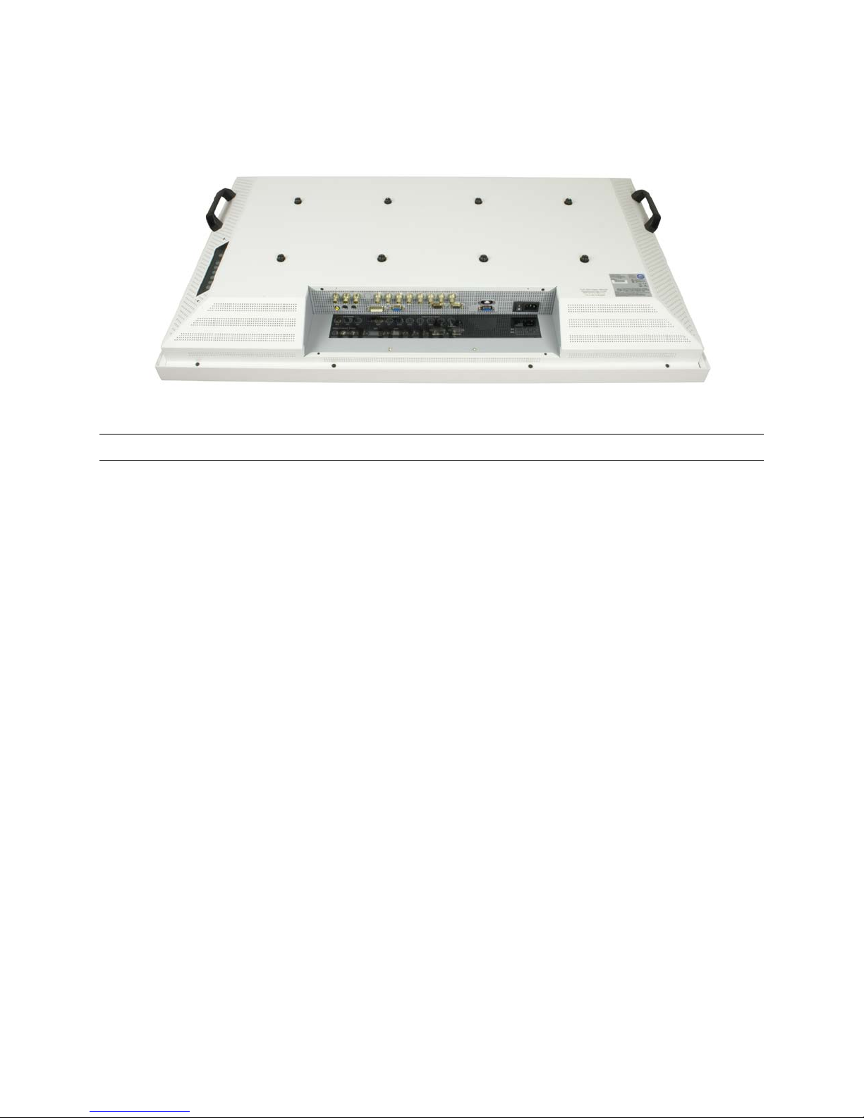
Figure 4: VividImage Monitor Rear View
Configuring Touch Capability
MON-VTS42SDI-MT and MON-VTS52SDI-MT touch enabled monitors come preconfigured for use as a touch panel.
To use the touch capability, a connection to the RS232 Touch Control port or USB Touch port must be made to the
system you wish to control with the touch panel. If neither of these ports is used, the monitor functions as a monitor
only, with no touch capability.
Should you ever need to reconfigure the touch panel, the Crystal Touch Manager Configuration Utility CD is included
with the monitor. Please save this CD. To run the Crystal Touch Manager Configuration Utility, a computer with a
CD player must be connected to the monitor with a USB or RS-232 cable.
Document # 82070-637, Revision C CONFIDENTIAL © 2009 Copyright VTS Medical Systems, LLC
8 of 29
1 2 3
4
5
6
7
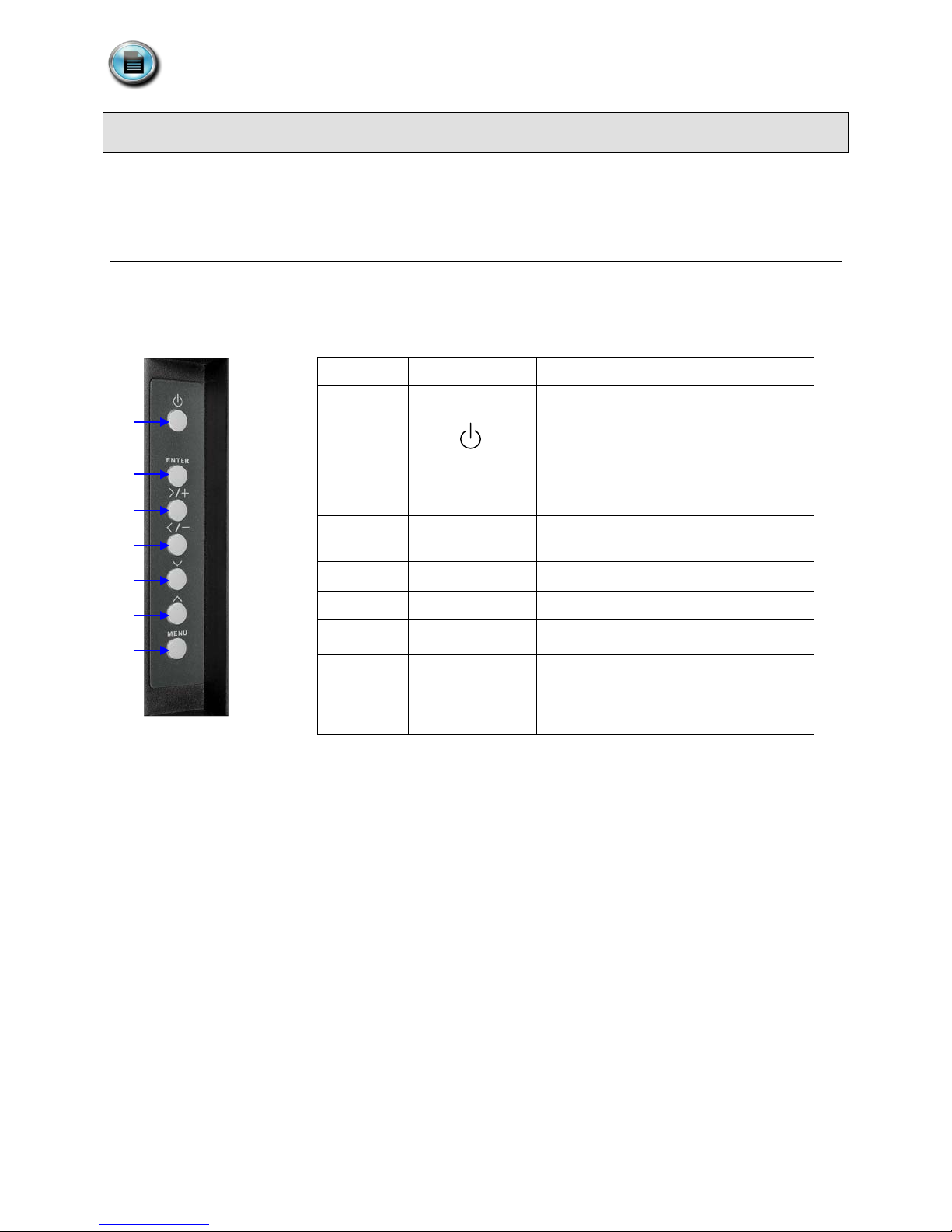
Control Devices
No.
Button
Description
The monitor comes with two control devices: A side control panel on the monitor and a remote control. This section
covers how to use and maintain these control devices.
Side Control Panel
The side control panel consists of seven push buttons located on the side of the monitor. The side control panel is
shown in Figure 2 below.
1
Power On / Off
Green: Normal Operation
Orange: No Signal
Amber: Power Saving
Off: Power Off
Figure 5: The Side Control Panel, Table 2: Side Control Functions
2 ENTER
3 > / +
4 < / -
5
6
7 MENU
﹀
︿
Activate Selection (when in menu) / Input
Source Selection (when not in menu)
Menu Right / Value Increasing
Menu Left / Value Decreasing
Menu Down
Menu Up
Enter OSD (On Screen Display) Menu /
Exit OSD Menu or Select
Document # 82070-637, Revision C CONFIDENTIAL © 2009 Copyright VTS Medical Systems, LLC
9 of 29

Remote Control
3
Menu Up
4
ENTER
Enter a Selection or Advance to Next
Auto Adjust Clock, Phase, Horizontal and
Select Picture in Picture / Picture And
7
MENU
Displays the OSD Menu
9
Menu Down
10
EXIT
Exit the OSD Menu
11
SOURCE
Input Source Selection
1
2
3
4
5 6 7
8
9
10
11
12
This section describes the remote control functions and includes instructions on changing the remote control battery.
Overview of Remote Control Functions
The remote control has twelve push buttons, as shown in Figure 3, below.
Figure 6: The Remote Control, Table 3: Remote Control Functions
No. Button Description
1 POWER Power ON / OFF
2 Menu Left
5 AUTO
6 PIP
8 Menu Right
12 SWITCH
Vertical Position
Picture Display Features
Switch Picture In Picture (PIP) Main and
Secondary Window Images
Changing the Remote Control Battery
1. Push down and pull out battery compartment.
2. Insert one new 3V lithium battery.
Make sure the polarity ( + / -) of the battery is correct.
3. Close battery compartment.
Document # 82070-637, Revision C CONFIDENTIAL © 2009 Copyright VTS Medical Systems, LLC
10 of 29
Figure 7: Changing the Remote Control Battery

On Screen Display (OSD)
Color Menu
Image Menu
Display Menu
Advanced Menu
OSD Menu
Setup Menu
Sub-menu Items
The On Screen Display (OSD) is used to change monitor settings. This section includes an overview of the OSD
dialog box, detailed description of all OSD features, and instructions for locking the OSD.
Navigating OSD Menus
Follow the instructions below to navigate OSD menus.
1. Power on the monitor.
2. On the side control panel or remote control, press M
3. Press or to select main-menu items.
4. Press or to select sub-menu items.
5. Press E
6. Press or to modify the current setting of the function. Changes are saved automatically.
7. To exit the OSD menu or return to the previous selection, press M
NTER to enter the sub-menu item .
ENU.
ENU.
Document # 82070-637, Revision C CONFIDENTIAL © 2009 Copyright VTS Medical Systems, LLC
11 of 29
Figure 8: OSD Menu Layout

Details of OSD Menu Functions
The selections on each of the OSD menu pages, and the signal inputs for which they are available, are described in
this section.
Display Menu
Use the Display Menu to adjust the picture quality.
For VGA/DVI-A input For DVI-D and video input
Brightness
Contrast
Hue
Saturation
Sub-Menu Description
Brightness
Contrast
Hue
Saturation
Sharpness (HD-SDI input only)
Brightness
Contrast
Hue
Saturation
Sharpness
Note: Some menu items may not be displayed if the selected input does not support that f unct ion.
Adjusts the screen brightness. See Glossary, page 27 for more
information. The default setting is 64.
Adjusts the image contrast. See Glossary, page 27 for more information.
The default setting is 50.
Adjusts the clarity and depth of the red, blue, and green colors. See
Glossary, page 27 for more information. The default settings for all three
colors is 255.
Adjusts the color saturation. See Glossary, page 27 for more information.
Adjusts the image clarity. This function is available only when a
HD-SDI source is selected.
Table 4: Display Menu Functions
Document # 82070-637, Revision C CONFIDENTIAL © 2009 Copyright VTS Medical Systems, LLC
12 of 29

Image menu
Use the Image Menu to adjust technical settings that affect the image quality and position.
For the VGA/DVI-A input For the DVI-D and video input
Auto Adjust
N/A
Auto Balance
Phase
Clock
H-Position
V-Position
Sub-Menu Description
Auto Adjust
Auto Balance
Automatically adjusts picture position and minimizes image instability.
The default setting for this field is On.
Automatically adjusts image color.
Phase
Clock
H-Position
Adjust the image focus. This setting only affects VGA and DVI-A inputs.
See Glossary, page 27 for more information. The default setting is 0.
Adjust the clock setting. This setting only affects VGA and DVI-A inputs.
See Glossary, page 27 for more information. The default setting is 50.
Move the image left or right. The default setting is 51.
V-Position
Move the image up or down. The default setting is 49.
Note: Some menu items may not be displayed if the selected input does not support that function.
Table 5: Image Menu Functions
Document # 82070-637, Revision C CONFIDENTIAL © 2009 Copyright VTS Medical Systems, LLC
13 of 29

Color menu
Use the Color Menu to adjust technical settings that affect the image color.
For the VGA/DVI-A input For the DVI-D and video input
Gamma
Color Temp.
User Color
Gamma
Color Temp.
User Color
Black Level (except DVI-D)
Sub-Menu Description
Gamma
Color Temp.
User Color
Adjusts Gamma value. (Selections are: Native, 1.8, 2.0, 2.2, DICOM, User).
The default setting is 2.2.
Change the color temperature. (Sele ctio ns are: 6500K, 7500K, 8200K, 9300K,
Natural, User). The default setting is 9300K.
Adjust red/green/blue gain. This setting is available only when the Color Temp.
is set to “User.” The default setting for all colors is 255.
Adjust the black level of the screen. This function will affect only the video
Black Level
source selected. It is not available with the DVI-D signal input. See Glossary,
page 27 for more information.
Note: Some menu items may not be displayed if the selected input does not support that function.
Table 6: Color Menu Functions
Document # 82070-637, Revision C CONFIDENTIAL © 2009 Copyright VTS Medical Systems, LLC
14 of 29

Advanced menu
Use the Advanced Menu to adjust additional screen settings.
For the VGA/DVI-A input For the DVI-D and video input
Scaling
Zoom Mode
Start Screen
Auto Mode
LED Mode
Scaling
Zoom Mode
Start Screen
LED Mode
Sleep Mode
Sleep Mode
Sub-Menu Description
Changes the aspect ratio.
Fill All — Stretch an image to fill the screen. Use if image is not 4:3 aspect
Scaling
ratio.
Aspect Ratio — Displays a 4:3 image as large as possible without stretching
or cropping
Native — displays a 4:3 image without scaling (magnification)
Zoom Mode
Start Screen
Temporarily expand a selected portion of the image to full screen size while
maintaining the image aspect ratio. The zoom setting does not save.
Display the start screen when powering on.
Auto Mode
LED Mode
Turn On / Off the auto adjust function, which positions the image on the
screen.
Turn On / Off LED indicator light.
Sleep Mode
Set the display to automatically power off if there is no signal input for
8 seconds. Upon signal inp ut, the disp lay pow ers on again.
Table 7: Advanced Menu Functions
Document # 82070-637, Revision C CONFIDENTIAL © 2009 Copyright VTS Medical Systems, LLC
15 of 29

OSD Menu
Use the OSD Menu settings to adjust the appearance of the OSD menu.
For the VGA/DVI-A input For the DVI-D and video input
H-Position
V-Position
Rotation
Time Out
Language
H-Position
V-Position
Rotation
Time Out
Language
Sub-Menu Description
H-Position
Moves the OSD menu left and right.
V-Position
Moves the OSD menu up and dow n.
Rotation
Rotates the OSD menu.
Time Out
Adjusts the amount of time the OSD displays.
Language
Choose language to be used in screen menus. (Select ions are: English,
Chinese, French, German, Italian, Spanish). The default is English.
Table 8: OSD Menu Settings Functions
Document # 82070-637, Revision C CONFIDENTIAL © 2009 Copyright VTS Medical Systems, LLC
16 of 29

Setup menu
Use the Setup Menu settings to the initial monitor values.
For the VGA/DVI-A input For the DVI-D and video input
All Reset
Lock Mode
DVI Select
Information
ID
All Reset
Lock Mode
DVI Select
Information
ID
Sub-Menu Description
All Reset
Recall the default factory settings.
Lock Mode
Lock and unlock the OSD functions.
DVI Select
Select DVI-D or DVI-A source.
Information
Display firmware version, source and resolution.
ID
Choose the desired monitor ID connected to an external control device by the
RS-232 IN port. (The adjustment range of monitor ID is 1~250)
Note: The RS-232 IN port can be used to connect an external control device (such as a computer) to control the
monitor’s functions externally. The ID function is intended to be used with third party RS-232 control hardware and
software.
Table 9: Setup Menu Functions
Document # 82070-637, Revision C CONFIDENTIAL © 2009 Copyright VTS Medical Systems, LLC
17 of 29

Locking the OSD
To Lock the OSD
1. Press M
2. Select Setup Menu.
ENU.
Figure 9: Setup Menu
3. Press , to select the sub-menu items. Select LOCK MODE and press ENTER.
Document # 82070-637, Revision C CONFIDENTIAL © 2009 Copyright VTS Medical Systems, LLC
18 of 29
Figure 10: Setup Menu, Lock Mode Selected

ID
4. Save the settings. Press
, to select the Lock Mode, then press ENTER. The lock modes are:
• Off: Function keys are unlocked, press MENU to use OSD.
• Mode 1: All function keys except “Power” are locked.
• Mode 2: All function keys are locked except “Brightness” control and “Power.” Press M
brightness control menu.
ENU to use the
Figure 11: Setup Menu, Lock Mode Selections
5. Press MENU to exit the OSD menu.
• When Lock Mode is set to OFF, pressing Menu causes the following menu to appear:
Document # 82070-637, Revision C CONFIDENTIAL © 2009 Copyright VTS Medical Systems, LLC
19 of 29
Figure 12: Display Menu

• When Lock Mode is set to Mode 1, pres sing Menu causes the following menu to appear:
OSD locked
OSD unlocked
Figure 13: Brightness Function Selections
• When Lock Mode is set to Mode 2, pressing Menu causes the following menu to appear:
Figure 14: OSD Locked
Temporarily Overriding the OSD Lock
To temporarily override the lock setting when the Lock field is set to Mode 1 or Mode 2: Hold the key (the button
on back of the monitor) until the message “OSD unlocked” displays on screen. The OSD unlocks for 15 minutes then
reverts to its previous setting.
Figure 15: OSD Unlocked
Note: If you temporarily override the Mode 1 or Mode 2 Lock setting as detailed in the section above, it will relock
after 15 minutes. To maintain an unlock status, set the Loc k Mode to Off.
Document # 82070-637, Revision C CONFIDENTIAL © 2009 Copyright VTS Medical Systems, LLC
20 of 29

Adjusting Monitor Settings with Hot Key
Controls
The Hot Key function allows the user to easily adjust monitor settings without opening the OSD menus.
Input Source Selection
To select the input source:
• On the side menu control panel, press Enter.
• On the remote control, press Source.
• VGA: Acquire analog signal from the D-sub 15pin input.
• DVI-A: Acquire analog signal from the DVI input (or RGBSync input).
• DVI-D: Acquire digital signal from the DVI input.
• Composite: Acquire analog signal from the composite input.
• S-Video: Acquire analog signal from the S-Video input.
• Component: Acquire analog signal from the Y/Cb/Cr input.
• HD-SDI 1: Acquire digital signal from the HD-SDI input. (Option)
• HD-SDI 2: Acquire digital signal from the HD-SDI input. (Option)
Document # 82070-637, Revision C CONFIDENTIAL © 2009 Copyright VTS Medical Systems, LLC
21 of 29
Figure 16: Input Source Selections

Mode Item Selection
To select a color mode, on the remote control or side menu control panel, press (left).
• User Mode: Standard display operation.
Figure 17: Color Mode Selections
• BL Mode: Blue base mode.
• DICOM Mode: DICOM standard operation.
• CL Mode: Clear base mode.
Gamma Item Selection
To select a Gamma value, on the remote control or side menu control panel, press (right).
• LB Mode: Light box mode (for viewing X-rays).
Figure 18: Gamma Value Selection
• Native: Disables the gamma function.
• Gamma 1.8: 1.8 gamma value.
• Gamma 2.0: 2.0 gamma value.
Document # 82070-637, Revision C CONFIDENTIAL © 2009 Copyright VTS Medical Systems, LLC
22 of 29
• Gamma 2.2: 2.2 gamma value.
• DICOM: DICOM standard.
• User: Manually set a gamma value.

Using Picture In Picture (PIP) and
PAP
PIP
Picture And Picture (PAP) Modes
These features are available only through the remote control.
Selecting PIP and PAP modes
1. To display two signals in PIP (Picture In Picture) mode, press the PIP button on the remote control, then
select S
The SWITCH button swaps the Picture in Picture and main image sources .
2. To display two signals in PAP (Picture And Picture) mode, press PIP again.
OURCE.
3. To return to full screen viewing of the main image source last selected before entering PAP mode, select
PIP a third time.
Document # 82070-639, Revision C CONFIDENTIAL © 2009 Copyright VTS Medical Systems, LLC
23 of 29

Primary Source and Secondary Source Selection
— — —
— — —
— — — — —
— — — — —
— — — — —
— — — — —
The table below shows the availability of PIP and PAP functions according to the primary source signal type.
Secondary Source
VGA DVI-A DVI-D Composite S-Video Component HD-SDI 1 HD-SDI 2
VGA — — — ● ● ● ● ●
DVI-A
DVI-D
Composite ● ● ●
● ● ● ● ●
● ● ● ● ●
— — — — —
S-Video ● ● ●
Component ● ● ●
Primary Source
HD-SDI 1 ● ● ●
HD-SDI 2 ● ● ●
Key:
● PIP function enabled
— PIP function disabled
Table 10: PIP and PIP Function Availability for Signal Type Combinations
Document # 82070-639, Revision C CONFIDENTIAL © 2009 Copyright VTS Medical Systems, LLC
24 of 29

Monitor Care / Troubleshooting
Monitor Care
LCD Panel
VividImage® monitors feature an optical quality
acrylic panel specially coated for superior antireflective properties. The panel can be damaged
(scratched and/or clouded) if improper cleaning
solutions are used. The following products from
STERIS Corporation have been tested on the
panel and can be used for cleaning and
disinfecting to ensure the panel does not become
compromised*:
Coverage Spray HB Plus
STERIS Part # 162477
Coverage Spray TB Plus
STERIS Part # 1629B4
Cabinet
To not damage the powder-coated finish on the
monitor cabinet, the cleaning and disinfecting
products recommended above can be used.
*If the STERIS products are not available, a
mixture of 50% methyl or ethyl alcohol and 50%
water can be used to clean both the panel and
monitor cabinet.
Use a clean, soft, microfiber cloth to apply the
STERIS products and/or the alcohol and water
solution to the panel and cabinet.
Troubleshooting
Please follow these troubleshooting tips prior to
contacting customer support.
The image is not displayed on the screen
- Is the power cord connected properly?
- Are the power cord and AC outlet
functional?
- Are the computer and/or video source(s)
connected to the monitor properly?
- Are the computer and/or video source(s)
turned on?
- Is the main power switch on the back of the
monitor turned on?
- Has an input (video) signal been chosen
(see “Input Signal Selection” on page 13 of
this manual) that correlates to the video
input(s) on the monitor?
- Is the monitor connected to a computer that
is in power-saving mode (check computer
manual for this feature)?
- Is the video cable(s) functional?
The Remote Control does not work
- Is the battery inserted properly with the
positive and negative (+ & -) in the correct
position?
- Is the remote control pointed toward the
monitor?
- The battery may need to be changed.
The image is shifted or not centered
- In the “Display Setting” menu, use the
“position” settings to reorient.
- If using a scope, it may not be centered with
the camera head.
The image is glaring or dark
- Decrease/Increase the brightness of the
monitor by using the “Brightness” submenu
from the “Display” Main Menu.
- Decrease/Increase the “Black Level” of the
monitor by using the “Black Level” submenu
from the “Display” Main Menu.
- If using a camera as the video source,
perform a “White Balance” and check the
“Iris Control” on the camera (see camera’s
operating manual for instructions), if
applicable.
Document # 82070-639, Revision C CONFIDENTIAL © 2009 Copyright VTS Medical Systems, LLC
25 of 29

Specifications
42 inch
52 inch
MON-VTS42SDI-MD
MON-VTS42SDI-MT
MON-VTS52SDI-MD
MON-VTS52SDI-MT
INPUTS:
Composite ● ● ● ●
S-Video ● ● ● ●
RGBHV (computer)
● ● ●
●
DVI ● ● ● ●
HD-SDI/SDI
●1
●1
●1
●1
Serial RS232 Control
● ● ●
●
Serial RS232 Touch Control
● ●
USB Touch Control
● ●
OUTPUTS:
HD-SDI/SDI
●
●
●
●
Component
●
●
●
●
Serial RS232 ● ● ● ●
Resolution
1920 x 1080
1920 x 1080
1920 x 1080
1920 x 1080
High Definition
● ● ●
●
Aspect Ratio
16:9
16:9
16:9
16:9
Brightness
500 cd/m2
500 cd/m2
500 cd/m2
500 cd/m2
Contrast
4000 to 1
4000 to 1
1500 to 1
1500 to 1
Viewing Angle (horz & vert)
176º
176º
176º
176º
Dimensions (in / mm)
Width
40.4 / 1026.16
40.25 / 1022.3
49.88 / 1267
TBD
Height
24.4 / 619.76
24.25 / 615.9
30.25 / 768.4
TBD
Depth
5.0 / 127
5.50 / 139.7
5.63 / 143
TBD
Weight (lb / kg)
Certifications
FCC Compliance, CE
FCC Compliance, CE
FCC Compliance, CE
FCC Compliance, CE
LCD Technology
Active Matrix
Active Matrix
Active Matrix
Active Matrix
(Fahrenheit/Celcius)
5º to 35º C
5º to 35º C
5º to 35º C
5º to 35º C
Storage Temperature
(Fahrenheit/Celcius)
-4º to 140º F /
-20º to 60º C
-4º to 140º F /
-20º to 60º C
-4º to 140º F /
-20º to 60º C
-4º to 140º F /
-20º to 60º C
Case
Aluminum
Aluminum
Aluminum
Aluminum
Mounting Hole Pattern
VESA 200mm
VESA 200mm
VESA 200mm
VESA 200mm
Power Requirements
230 Watts max
230 Watts max
350 Watts max
350 Watts max
1
Two (2) total ports for both or either SDI and/or HD-SDI
VividImage Model #
Component ● ● ● ●
HD-YPbPr ● ● ● ●
42 inch
Touch Screen 52 inch
Touch Screen
Operating Temperature
Voltage: Monitor Input
76.5 / 34.7
(Medical Device
Directive), Canadian
ICES-003, CB (IEC
60950-1, IEC 60601-
1) UL (60950-1,
60601-1), CAN/CSA
C22.2 No. 601-1,
VCCI. PSE, BSMI,
CCC, RoHS, WEEE
41º to 95º F /
100 - 240V AC 100 - 240V AC 100 - 240V AC 100 - 240V AC
Table 11: Specifications
98 / 44.5 120.5 / 54.7 TBD
(Medical Device
Directive), Canadian
ICES-003, CB (IEC
60950-1, IEC 60601-1)
UL (60950-1),
CAN/CSA C22.2
No. 601-1, VCCI. PSE,
BSMI, CCC, RoHS,
WEEE
41º to 95º F /
(Medical Device
Directive), Canadian
ICES-003, CB (IEC
60950-1, IEC 60601-
1) UL (60950-1,
60601-1), CAN/CSA
C22.2 No. 601-1,
VCCI. PSE, BSMI,
CCC, RoHS, WEEE
41º to 95º F /
(Medical Device
Directive), Canadian
ICES-003, CB (IEC
60950-1, IEC 60601-
1) UL (60950-1),
CAN/CSA C22.2
No. 601-1, VCCI.
PSE, BSMI, CCC,
RoHS, WEEE
41º to 95º F /
Document # 82070-639, Revision C CONFIDENTIAL © 2009 Copyright VTS Medical Systems, LLC
26 of 29

Glossary
Color Number 1 Proportions
Bias Increase
New Color Proportions
Color Number 2 Proportions
Bias Increase
New Color Proportions
Red = 60%
5%
Red = 60% + 5% = 65%
Green = 40%
0%
Green = 40%
Black Level: This adjustment allows the display to be set to discriminate between small differences in dark or near
black areas of the image. The adjustment should make a black area of the image (such as a deep shadow where all
detail is lost in the image) appear black. The black level is decreased (less black) until a change toward light or grey
is perceived in this area, then the adjustment increases slightly to restore the dark area to black. It is important to
perform this adjustment on a truly black area in the image to avoid making dark areas appear lighter than they
actually are.
Brightness: The intensity of light emitted from the LCD Display. This control is similar to the effect of changing the
light behind a stained glass window. As the illumination is increased the overall light output of the image is increased.
The proper adjustment takes into consideration the ambient light in the room. For a brightly lit room, the brightness of
the display may be increased to improve the visibility of the image. In a dimly lit room, the brightness may be
decreased to reduce the impact on the eye.
Clock: This adjustment is seldom necessary, but if there is a problem with the frequency of the monitor pixel clock
so that it cannot exactly match the clock signal from the camera, an adjustment may be required. The symptom of a
clock adjustment problem is the appearance of vertical bands in the image. Adjusting the clock will help eliminate
these artifacts.
Contrast: Contrast is the differentiation between variations of similar colors. Typically contrast is set by adjusting for
best color differentiation between light yellow and white.
Hue: Hue refers to the “shade” of the colors. These adjustments primarily affect analog signal sources. S-Video,
RGBHV and VGA are analog signals. Adjusting the hue will help to correct abnormalities in the signal. The
adjustment can help restore the “natural” look of the colors.
Phase: This adjustment is seldom necessary, but if there is a problem with the monitor pixel clock phase or position
in relation to the pixel clock generated by the camera, a phase adjustment may be required. The symptom of phase
problems is the appearance of horizontal lines flickering through the image.
Red, Green, Blue Color Adjustment: Increasing the bias of a color increases the proportion of that color in the
image. The level of the selected color is varied equally for all proportions. For example:
Red = 20% 5% Red = 20% + 5% = 25%
Green = 70% 0% Green = 70%
Blue = 40% 0% Blue = 40%
Blue = 30% 0% Blue = 30%
Note that Red has been increased by 5% regardless of its original proportion.
Since increasing the bias will add additional proportions of the color, care must be taken to assure that variations for
very weak and very intense sections of the image do not lose their “Contrast” (ability to detect subtle variations
between colors).
Saturation: Saturation refers to the purity of any particular color component (Red, Green or Blue). For example,
100% Red saturation is 100% Red, 0% Green and 0% Blue. No saturation means all the color percentages are
equal. Changes in saturation will change the emphasis of the selected color component.
Document # 82070-639, Revision C CONFIDENTIAL © 2009 Copyright VTS Medical Systems, LLC
27 of 29

Index
A
Accessory Checklist, 5
Aspect Ratio, 15
Auto Balance Color, 13
B
Black Level, 14, 27
Brightness, 12, 27
C
Care, 25
Clock, 13, 27
Color Menu, 14
Color Mode Selection, 22
Color Temperature, 14
Connecting, 6
Connecting Video Cables, 7
Contact Customer Support, 29
Contrast, 12, 27
Control Devices, 9
Control Panel, Side, 9
D
Display Menu, 12
F
Factory Default Settings, 17
Firmware Version, 17
G
Gain. See Color Temperature
Gamma, 14
Gamma Value Selection, 22
Glossary, 27
H
O
On Screen Display, 11
OSD, 11, 25
Menu Functions, 12
Navigation, 11
OSD Menu
Language, 16
Lock, 18
Settings, 16
Time Out, 16
P
Phase, 13, 27
Picture Position, 13
Picture-And Picture (PAP), 23
Picture-In-Picture (PIP), 23
Power Cord, 8
Precautions, 5
R
Remote Control, 10
Batteries, 10
Functions, 10
S
Safety, 5
Saturation, 12, 27
Setup Menu, 17
Sharpness, 12
Signal Selection, 21
Sleep, 15
Specifications, 26
T
Tips, 5
Touch Configuration, 8
Troubleshooting, 25
Horizontal Position, 13
Hue, 12, 27
L
LED On/Off, 15
M
Monitor Care, 25
Mounting, 7
Document # 82070-639, Revision C CONFIDENTIAL © 2009 Copyright VTS Medical Systems, LLC
28 of 29
U
Unpacking, 6
V
Vertical Position, 13
Video Inputs, 7
Z
Zoom, 15

Contact VTS Customer Support
VividImage®
40 Melville Park Road
Melville, NY 11747
(877) VTS-1788
is a registered trademark of VTS Medical Systems, LLC
Document # 82070-639, Revision C CONFIDENTIAL © 2009 Copyright VTS Medical Systems, LLC
29 of 29
 Loading...