

VTS Medical Systems VividImage MON-VTS42SDI-MT, VividImage MON-VTS42SDI-MD, VividImage MON-VTS52SDI-MD, VividImage MON-VTS52SDI-MT Operation Manual
MON-VTS42SDI-MD
VividImage
Medical Grade
High Definition Wide Screen Monitor
®
OPERATION MANUAL
MON-VTS42SDI-MD
MON-VTS42SDI-MT
MON-VTS52SDI-MD
MON-VTS52SDI-MT
Document # 82070-639, Revision C CONFIDENTIAL © 2009 Copyright VTS Medical Systems, LLC
1 of 29

Notice for Users
IMPORTANT:
To aid in reporting in the case of loss or theft, or for
service maintenance purposes, please record the
monitor’s model and serial numbers in the space
provided. The numbers are located on the rear of
the monitor.
FCC Statement
WARNING — FCC Regulations state that any unauthorized changes or modifications to this equipment not
expressly approved by the manufacturer could void the user’s authority to operate this equipment.
Note: This equipment has been tested and found to comply with the limits for a Class A digital device, pursuant to
Part 15 of the FCC Rules.
These limits are designed to provide reasonable protection against harmful interference when the equipment is
operated in a commercial environment. This equipment generates, uses, and can radiate radio frequency energy
and, if not installed and used in accordance with the instruction manual, may cause harmful interference to radio
communications. Operat ion of this equip ment in a reside ntia l area is likely to cause harmful interference in which
case the user will be required to correct the interference at his own expense.
Declaration of Conformity
MON-VTS42SDI-MD / MON-VTS52SDI-MD:
This device has been evaluated to the UL 60601-1 standard:
Equipment evaluated to this standard is not suitable for use in the presence of a flammable anesthetic mixture
with air or with oxygen or nitrous oxide (unless additional tests have been passed). Therefore this device is not
suitable for use in the presence of a flammable anesthetic mixture with air or with oxygen or nitrous oxide.
MON-VTS42SDI-MD / MON-VTS42SDI-MT / MON-VTS52SDI-MD / MON-VTS52SDI-MT:
This device complies with Part 15 of the FCC Rules. Operation is subject to the following two conditions: (1) this
device may not cause harmful interference, and (2) this device must accept any interference received, including
interference that may cause undesired operation.
Function, Intended Application and Mode of Operation:
The VividImage Series of monitors are intended to be used in the displaying and viewing of video and graphics for
review and analysis by trained medical practitioners. The mode of operation for this device is continuous
operation.
For a complete list of current certifications, please refer to the Specifications page of this manual.
Model No:
Serial No:
Document # 82070-637, Revision C CONFIDENTIAL © 2009 Copyright VTS Medical Systems, LLC
2 of 29

Table of Contents
Notice for Users ........................................................................................................................................................... 2
FCC Statement ......................................................................................................................................................... 2
Declaration of Conformity .......................................................................................................................................... 2
Tips and Safety Precautions ....................................................................................................................................... 5
Monitor and Accessory Checklist .............................................................................................................................. 5
Mounting ................................................................................................................................................................... 5
Location ..................................................................................................................................................................... 5
Power Cord ............................................................................................................................................................... 5
Manual Scope ........................................................................................................................................................... 5
Connecting and Powering On the Monitor................................................................................................................. 6
Unpacking the carton .................................................................................................................................................. 6
Figure 1: Included Cables ..................................................................................................................................... 6
Mounting the Monitor .................................................................................................................................................. 7
Figure 2: Mounting Holes ...................................................................................................................................... 7
Connecting the Video Inputs....................................................................................................................................... 7
Table 1: Inputs and Connections .......................................................................................................................... 7
Figure 3: Connecting the Power Cord ................................................................................................................... 7
Figure 4: VividImage Monitor Rear View .............................................................................................................. 8
Configuring Touch Capability ..................................................................................................................................... 8
Control Devices ............................................................................................................................................................ 9
Side Control Panel ....................................................................................................................................................... 9
Figure 5: The Side Control Panel, Table 2: Side Control Functions...................................................................... 9
Remote Control .......................................................................................................................................................... 10
Overview of Remote Control Functions ................................................................................................................... 10
Figure 6: The Remote Control, Table 3: Remote Control Functions ................................................................... 10
Changing the Remote Control Battery..................................................................................................................... 10
Figure 7: Changing the Remote Control Battery ................................................................................................. 10
On Screen Display (OSD) .......................................................................................................................................... 11
Navigating OSD Menus .............................................................................................................................................. 11
Figure 8: OSD Menu Layout ............................................................................................................................... 11
Details of OSD Menu Functions ................................................................................................................................ 12
Display Menu .......................................................................................................................................................... 12
Table 4: Display Menu Functions........................................................................................................................ 12
Image menu ............................................................................................................................................................ 13
Table 5: Image Menu Functions ......................................................................................................................... 13
Color menu .............................................................................................................................................................. 14
Table 6: Color Menu Functions ........................................................................................................................... 14
Advanced menu ...................................................................................................................................................... 15
Table 7: Advanced Menu Functions ................................................................................................................... 15
Table 8: OSD Menu Settings Functions .............................................................................................................. 16
Setup menu ............................................................................................................................................................. 17
Table 9: Setup Menu Functions .......................................................................................................................... 17
Document # 82070-637, Revision C CONFIDENTIAL © 2009 Copyright VTS Medical Systems, LLC
3 of 29

Locking the OSD ........................................................................................................................................................ 18
To Lock the OSD ..................................................................................................................................................... 18
Figure 9: Setup Menu ......................................................................................................................................... 18
Figure 10: Setup Menu, Lock Mode Selected ..................................................................................................... 18
Figure 11: Setup Menu, Lock Mode Selections .................................................................................................. 19
Figure 12: Display Menu ..................................................................................................................................... 19
Figure 13: Brightness Function Selections ......................................................................................................... 20
Figure 14: OSD Locked ...................................................................................................................................... 20
Temporarily Overriding the OSD Lock ..................................................................................................................... 20
Figure 15: OSD Unlocked ................................................................................................................................... 20
Adjusting Monitor Settings with Hot Key Controls ................................................................................................. 21
Input Source Selection .............................................................................................................................................. 21
Figure 16: Input Source Selections ..................................................................................................................... 21
Mode Item Selection .................................................................................................................................................. 22
Figure 17: Color Mode Selections....................................................................................................................... 22
Gamma Item Selection ............................................................................................................................................... 22
Figure 18: Gamma Value Selection .................................................................................................................... 22
Using Picture In Picture (PIP) and Picture And Picture (PAP) Modes .................................................................. 23
Selecting PIP and PAP modes ................................................................................................................................ 23
Primary Source and Secondary Source Selection .................................................................................................. 24
Table 10: PIP and PIP Function Availability for Signal Type Combinations ........................................................ 24
Monitor Care / Troubleshooting ................................................................................................................................ 25
Monitor Care ........................................................................................................................................................... 25
Troubleshooting ...................................................................................................................................................... 25
Specifications ............................................................................................................................................................. 26
Table 11: Specifications ...................................................................................................................................... 26
Glossary ...................................................................................................................................................................... 27
Index ............................................................................................................................................................................ 28
Document # 82070-637, Revision C CONFIDENTIAL © 2009 Copyright VTS Medical Systems, LLC
4 of 29

Tips and Safety Precautions
- Do not display a still image for ten (10) or more
hours. An afterimage may remain.
- It may be difficult to see the image on the
screen if the brightness is adjusted to the
minimum s etting.
- The quality of the video signal may influence the
quality of the displayed image.
- Do not open the monitor.
- When unpacking, carrying or mounting the
monitor at least two people are needed. Make
sure the monitor is in the upright position.
Monitor and Accessory Checklist
- Included in the carton are the following items:
1 VividImage HD Wide Screen Monitor
1 DVI Cable
1 VGA Cable
1 S-Video Cable
1 Power Cable
1 Remote
8 Mounting Screws (attached to the monitor)
1 Touch Setup CD (MON-VTS42-SDI-MT /
MON-VTS52SDI-MT only)
1 Quick Start Guide
Notes:
- Retain the carton and packing material for
storing or transporting the monitor.
Mounting
- Always follow mounting instru c tion s to avoid
physical injury and/or damage to the monitor .
Location
- Use the monitor in a suitable environment. See
“Operating Temperature” and “Storage
Temperature” on the Specifications page of this
manual.
- Use caution around liquids as you would with
any electrical appliance.
- Do not insert objects into the monitor.
- Do not place the monitor on unstable surfaces.
- In all cases, refer to the specifications in this
manual to ensure proper monitor performance.
Use of the monitor outside of operating
specifications will void the monitor warranty and
may cause permanent damage to the monitor.
Power Cord
- Do not damage the power cord. Damage to the
cord may result in fire or electric shock.
- Do not add extension cords.
- Use only the power cord included with the
monitor.
- Insert the power plug directly into the AC outlet.
- Do not remove or insert the power plug with wet
hands. Doing so could result in electric shock.
Manual Scope
- This manual is written for use with the MONVTS42SDI-MD /MON-VTS42SDI-MT/ MONVTS52SDI-MD/MON-VTS52SDI-MT. When
describing a different specifi ca tion between the
models, the model number is given. (When the
model number is not given, the description is
true for both models. For product appearance,
illustrations of model MON-VTS42HD-MD are
used in this manual.)
Document # 82070-637, Revision C CONFIDENTIAL © 2009 Copyright VTS Medical Systems, LLC
5 of 29
Connecting and Powering On the Monitor
1 VividImage HD Wide Screen Monitor
This section includes all the information you need to start using your new monitor.
Unpacking the carton
Included in the carton are the following items:
1 DVI cable
1 VGA cable
1 S-Video Cable
1 Power Cable
1 Remote
8 Mounting Screws (Attached to the monitor)
1 Touch Setup CD (MON-VTS42SDI-MT / MON-VTS52SDI-MT only)
1 Quick Start Guide
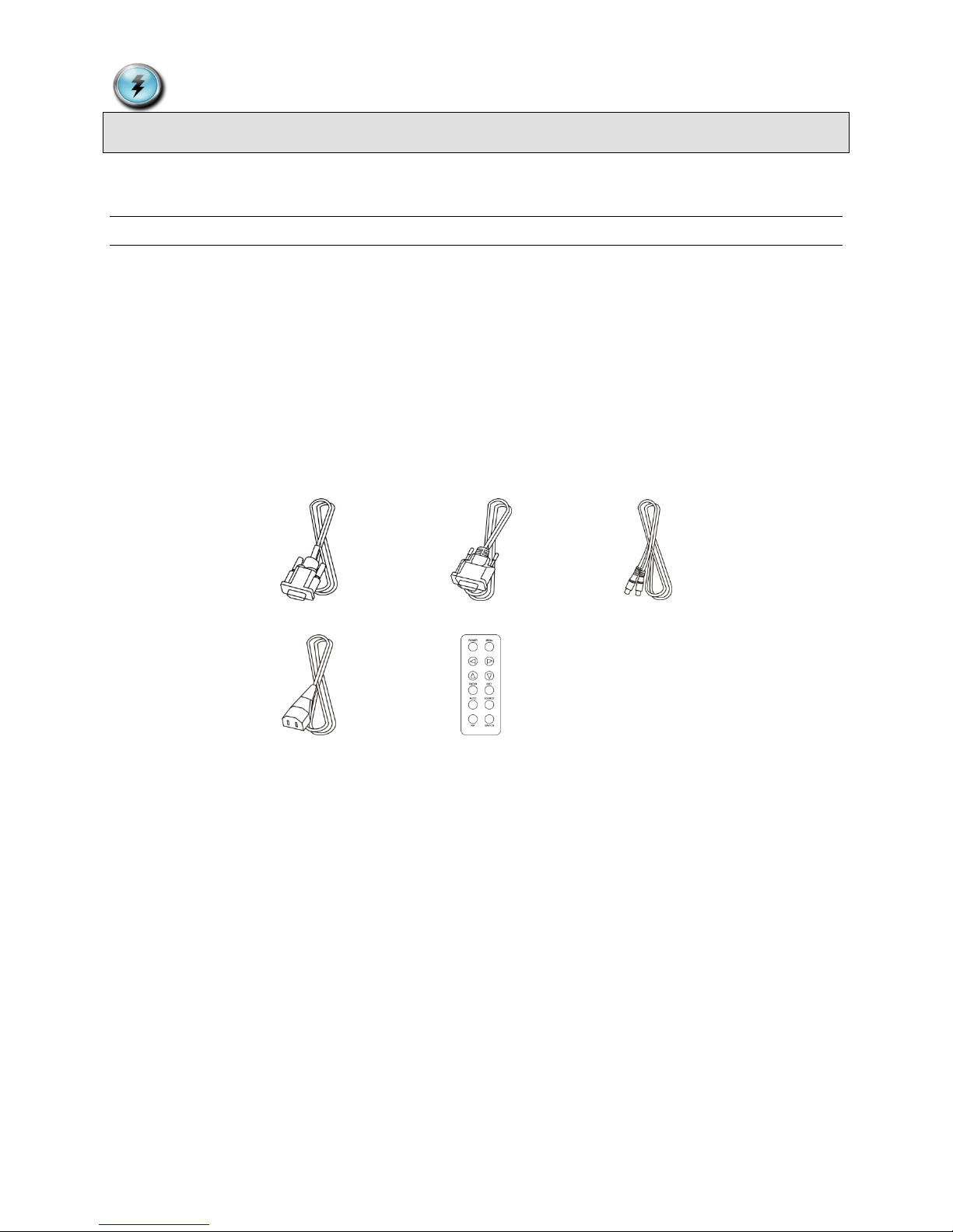
1 DVI Cable 1 VGA Cable 1 S-Video Cable
1 Power Cord 1 Remote Control
Figure 1: Included Cables
If any one of these items is missing, please call VTS Customer Support at (877) VTS-1788.
Document # 82070-637, Revision C CONFIDENTIAL © 2009 Copyright VTS Medical Systems, LLC
6 of 29
Mounting the Monitor
Y/Cb/Cr input
8pin Mini Din (x1)
S-Video input
4pin Mini Din (x1)
Video Input
RCA Jack (x1)
HD-SDI input (Option)
BNC Connector (x3)
RGBSync input (Option)
BNC Connector (x8)
RS-232 control (IN/OUT)
D-Sub 9 pin
USB Touch control( MON-VTS42SDI-MT / MON-VTS52SDI-MT only)
USB-A
RS-232 Serial Touch control (MON-VTS42SDI-MT / MON-VTS52SDI-MT only)
D-Sub 9 pin
AC Switch / Power cord input
AC Power Input
Eight mounting
These ports available on MON-VTS42SDI-MT /
MON-VTS52SDI-MT only
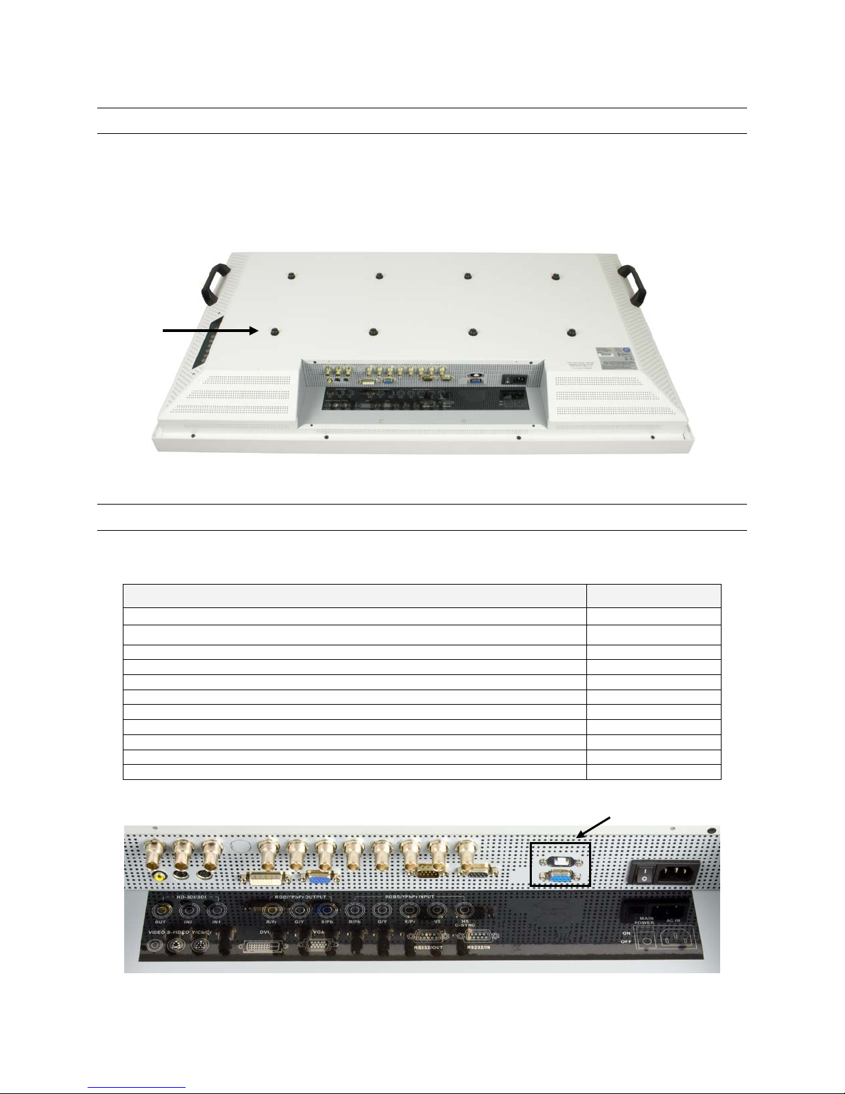
The monitor can be mounted using the eight included screws. The hole pattern for the eight screws neede d to mount
the monitor can be seen in the drawing below.
Unscrew the eight screws from the back cover. It is recommended that you use all eight screws when mounting the
monitor using a wall mount kit (not included). You must use at least four of the screws, either in the four center holes
or the four outer holes. Follow the directions that come with the wall mount kit to complete the installation.
holes and screws
Figure 2: Mounting Holes
Connecting the Video Inputs
The video input cable(s) should be attached to the appropriately labeled ports on the back of the monitor as shown
below. The following inputs are available:
Name Connection Type
VGA (RGB) input D-Sub 15pin (x1)
DVI input DVI-D (x1)
Table 1: Inputs and Connections
Figure 3: Connecting the Power Cord
Document # 82070-637, Revision C CONFIDENTIAL © 2009 Copyright VTS Medical Systems, LLC
7 of 29
Plug the appropriate end of the power cord into the 3-pronged interface on the back of the monitor. Plug the other
end of the power cord into an outlet and turn the main power switch to on.
Input: 100-240 Volts (V) ~ 3 Amperes (A) 50/60 Hertz (Hz)
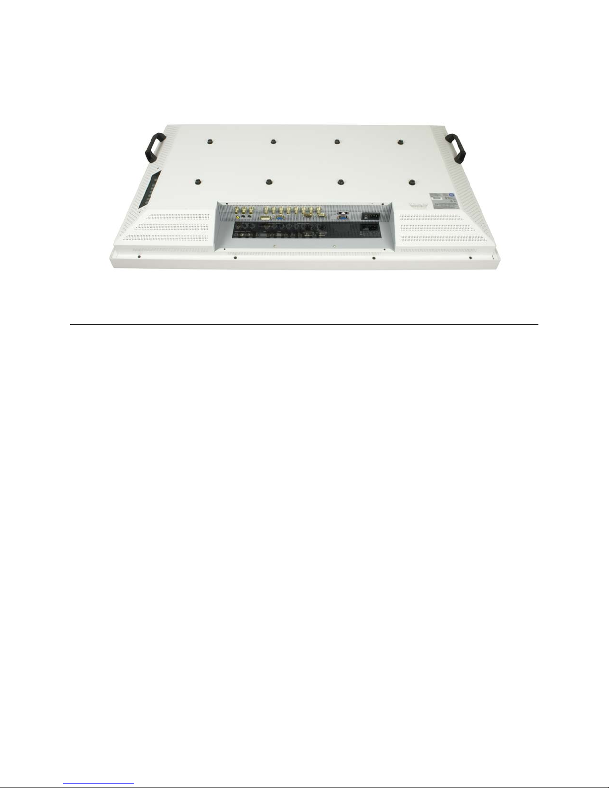
Figure 4: VividImage Monitor Rear View
Configuring Touch Capability
MON-VTS42SDI-MT and MON-VTS52SDI-MT touch enabled monitors come preconfigured for use as a touch panel.
To use the touch capability, a connection to the RS232 Touch Control port or USB Touch port must be made to the
system you wish to control with the touch panel. If neither of these ports is used, the monitor functions as a monitor
only, with no touch capability.
Should you ever need to reconfigure the touch panel, the Crystal Touch Manager Configuration Utility CD is included
with the monitor. Please save this CD. To run the Crystal Touch Manager Configuration Utility, a computer with a
CD player must be connected to the monitor with a USB or RS-232 cable.
Document # 82070-637, Revision C CONFIDENTIAL © 2009 Copyright VTS Medical Systems, LLC
8 of 29
1 2 3
4
5
6
7
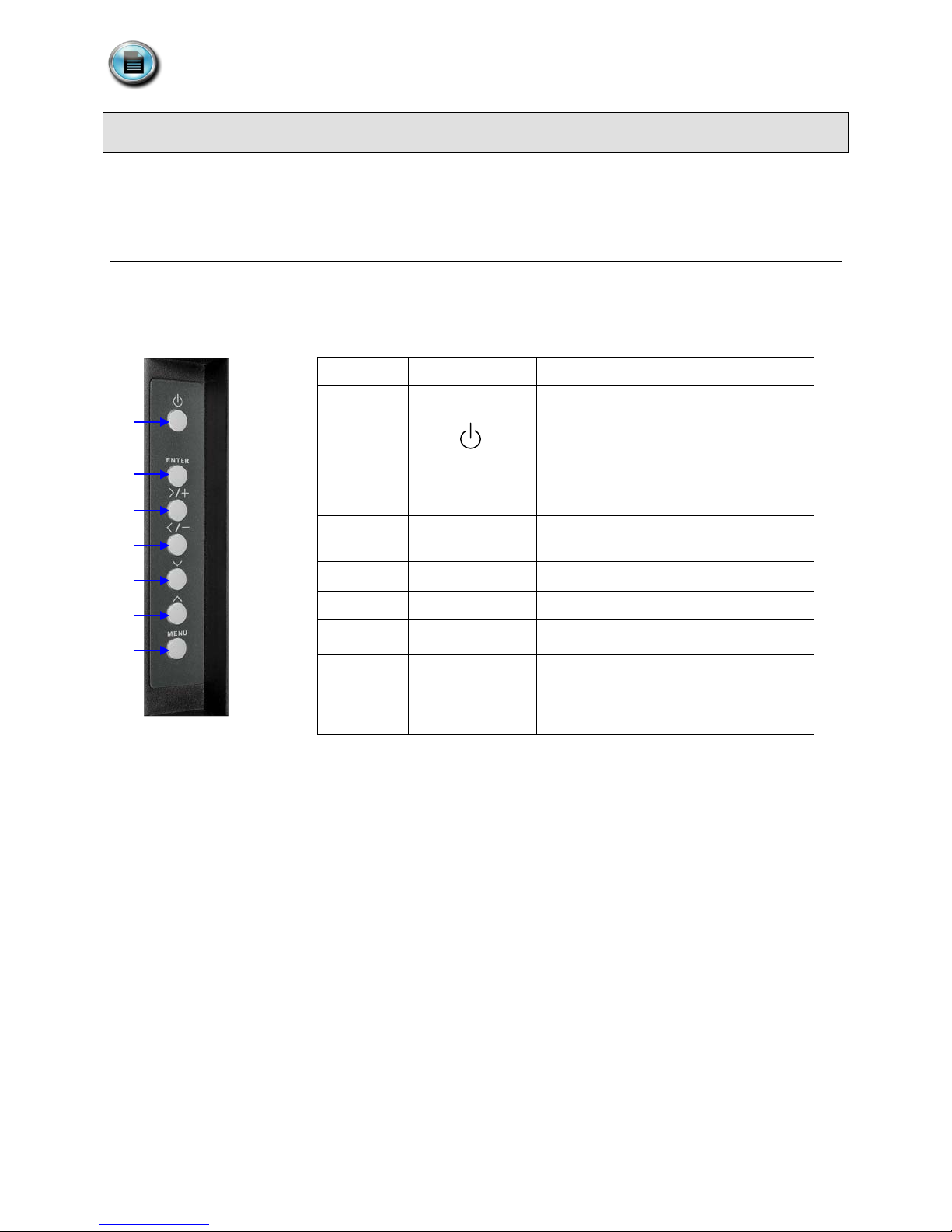
Control Devices
No.
Button
Description
The monitor comes with two control devices: A side control panel on the monitor and a remote control. This section
covers how to use and maintain these control devices.
Side Control Panel
The side control panel consists of seven push buttons located on the side of the monitor. The side control panel is
shown in Figure 2 below.
1
Power On / Off
Green: Normal Operation
Orange: No Signal
Amber: Power Saving
Off: Power Off
Figure 5: The Side Control Panel, Table 2: Side Control Functions
2 ENTER
3 > / +
4 < / -
5
6
7 MENU
﹀
︿
Activate Selection (when in menu) / Input
Source Selection (when not in menu)
Menu Right / Value Increasing
Menu Left / Value Decreasing
Menu Down
Menu Up
Enter OSD (On Screen Display) Menu /
Exit OSD Menu or Select
Document # 82070-637, Revision C CONFIDENTIAL © 2009 Copyright VTS Medical Systems, LLC
9 of 29
 Loading...