

VTS Medical Systems VENTUS Owner's Operation And Maintenance Manual
www.vtsgroup.us
EN
Operation and Maintenance Manual
VENTUS Suspended Air–Handling Units
Rated air flow range 400 – 1600 m3/h
OMM–VVS–ver.1.6 (05.2018)

OMM–VTS–ver.1.6 (05.2018) 2
Table of content
1 Warming, Cautions and Notices .................................................................... 6
2 Model Descriptions ........................................................................................ 7
3 General Information ....................................................................................... 8
4 Pre–Installation ............................................................................................ 11
4.1 Transport and storage ........................................................................... 11
4.1.1 Receiving Checklist ......................................................................... 11
4.2 Installation Preparation .......................................................................... 12
4.2.1 Unit Location Recommendations .................................................... 12
4.2.2 Assembly in suspended position ..................................................... 12
4.2.3 Setting in vertical position ............................................................... 15
4.2.4 Connecting the ventilation ducts ..................................................... 15
4.2.5 Connection of heaters and coolers ................................................. 16
4.2.6 Draining out condensate ................................................................. 18
4.2.7 Electric connection .......................................................................... 19
4.3 Service Access ...................................................................................... 19
4.3.1 Skid Removal .................................................................................. 20
4.4 AHU components .................................................................................. 20
4.4.1 Hydronic coil exchangers ................................................................ 20
4.4.2 DX Coils .......................................................................................... 21
4.4.3 Electric Heaters ............................................................................... 22
4.4.4 Fan’s motors ................................................................................... 24
4.4.5 Air Filters ......................................................................................... 25
5 Automation .................................................................................................. 26
5.1 Description of controls ........................................................................... 26
5.1.1 Introduction ..................................................................................... 26
5.1.2 Mains switch ................................................................................... 26
5.1.3 Communication port ........................................................................ 26
5.1.4 Signaling controller status ............................................................... 26
5.1.5 Simplified control panel – HMI Basic UPC ...................................... 27
5.2 System Start–Up ................................................................................... 28
5.2.1 Switching on power supply.............................................................. 28
5.2.2 HMI Advanced UPC ........................................................................ 29
5.2.3 Langauge Selection ........................................................................ 29
5.2.4 Entering the password .................................................................... 29
5.2.5 Selection of operating mode ........................................................... 29

OMM–VTS–ver.1.6 (05.2018)
www.vtsgroup.us 3
5.2.6 Indication od operating mode .......................................................... 30
5.3 System operation ................................................................................... 31
5.3.1 Operating mode .............................................................................. 31
5.4 Calendar ................................................................................................ 31
5.4.1 Calendar – Main page ..................................................................... 31
5.4.2 Calendar – Day (Monday) ............................................................... 32
5.4.3 Calendar – Special .......................................................................... 32
5.4.4 Calendar – Exceptions .................................................................... 32
5.4.5 Calendar mode in HMI Basic .......................................................... 32
5.5 Parameters ............................................................................................ 33
5.5.1 Parameters – Air temperatures ....................................................... 33
5.5.2 Parameters – Humidity ................................................................... 33
5.5.3 Parameters – Humidity control ........................................................ 33
5.5.4 Parameters – Supply / Exhaust fan & dampes ................................ 33
5.5.5 Parameters – Heating ..................................................................... 34
5.5.6 Parameters – Recovery .................................................................. 34
5.5.7 Parameters – Cooling ..................................................................... 35
5.5.8 Parameters – Pre–Heating.............................................................. 35
5.5.9 Parameters – Supply / Exhaust motors ........................................... 35
5.5.10 Parameters – Supply / Exhaust pressure transducer ...................... 35
5.5.11 Parameters – Supply / Exhaust air flow transducer ........................ 36
5.5.12 Parameters –Redundan .................................................................. 36
5.6 Settings ................................................................................................. 36
5.6.1 Settings –Timers ............................................................................. 36
5.6.2 Settings – Standby .......................................................................... 36
5.6.3 Settings – Night test ........................................................................ 36
5.6.4 Settings – Fast heating ................................................................... 37
5.6.5 Settings – Temperatures ................................................................. 37
5.6.6 Settings – Humidity control ............................................................. 37
5.6.7 Settings – Fans ............................................................................... 37
5.6.8 Settings – Water heater .................................................................. 38
5.6.9 Settings – Init heating ..................................................................... 38
5.6.10 Settings – Water heater .................................................................. 38
5.6.11 Settings – DX Cooler ...................................................................... 39
5.6.12 Settings – Water Pre–heater ........................................................... 39
5.6.13 Settings – Init pre–heating .............................................................. 40
5.6.14 Settings – Fan regulators ................................................................ 40

OMM–VTS–ver.1.6 (05.2018)
www.vtsgroup.us 4
5.6.15 Settings – Pressure regulators ........................................................ 40
5.6.16 Settings – Temperature regulators .................................................. 40
5.6.17 Settings – Manual mode ................................................................. 41
5.6.18 Settings – Frequence converter RRG ............................................. 42
5.6.19 Settings – Fans fire mode ............................................................... 42
5.6.20 Settings – Universal regulator ......................................................... 42
5.7 Alarm menu ........................................................................................... 43
5.8 Advanced manual .................................................................................. 44
5.8.1 Service menu .................................................................................. 44
5.8.2 Service menu – Config page ........................................................... 44
5.8.3 Service menu – Outputs ................................................................. 49
5.8.4 Service menu – Frq. Converters configuration ................................ 50
5.8.5 System info ..................................................................................... 50
5.9 Control algorithms ................................................................................. 50
5.10 Technical data .................................................................................... 53
5.10.1 Operation parameters ..................................................................... 53
5.10.2 Carel µPC controller ........................................................................ 53
5.10.3 Cabling ............................................................................................ 53
5.11 Connection ......................................................................................... 55
5.11.1 Standard connection ....................................................................... 55
5.11.2 Power connection ........................................................................... 55
5.11.3 Connection of automation elements ................................................ 55
6 Preparation for start–up ............................................................................... 59
6.1 Electrical system .................................................................................... 59
6.2 Filters ..................................................................................................... 59
6.3 Water heaters ........................................................................................ 59
6.4 Electric heaters ...................................................................................... 60
6.5 Water and freon coolers ........................................................................ 60
6.6 Counter–flow heat exchangers .............................................................. 60
6.7 Fan unit ................................................................................................. 60
7 Start–up and adjustment ............................................................................. 61
7.1 Measurement of air quantity and AHU output adjustment. .................... 61
7.2 Heat output adjustment of water heater ................................................. 62
7.3 Adjustment of electric heater ................................................................. 62
7.4 Adjustment of cooler performance ......................................................... 62
8 Operation and maintenance ........................................................................ 63
8.1 Dampers ................................................................................................ 63

OMM–VTS–ver.1.6 (05.2018)
www.vtsgroup.us 5
8.2 Filters ..................................................................................................... 64
8.3 Heat exchangers ................................................................................... 64
8.3.1 Water heater ................................................................................... 64
8.3.2 Electric Heater ................................................................................ 65
8.3.3 Water cooler .................................................................................... 65
8.3.4 Freon cooler and heater .................................................................. 65
8.3.5 Counter flow heat exchanger .......................................................... 65
8.4 Silencer section ..................................................................................... 66
8.5 Fan unit ................................................................................................. 66
9 Safety instructions ....................................................................................... 67
10 Information .................................................................................................. 67
11 Technical information to the regulation (U) No 327/2011 ............................ 68

OMM–VTS–ver.1.6 (05.2018)
www.vtsgroup.us 6
In–depth familiarization with the content of this manual, assembly, start–up and operation
of the air handling unit in line with the instructions provided and following all safety regulations will
ensure the basis of efficient, safe and non–failure operation of the device.
This operation and maintenance manual does not cover all possible variants of the unit’s
configurations, examples of their assembly and installation as well as start–up, operating, repairing
and maintenance. If the units are used for what they are intended, this documentation and any
other materials provided with the unit contain information designed for the qualified technical
personnel only.
1 Warming, Cautions and Notices
SAFETY WARNING!
• The installation, starting up, and servicing air handling units and their equipment can be
hazardous and requires specific knowledge and training.
• Improperly installed, adjusted or altered equipment by an unqualified person could result
in death or serious injury.
• When working on the equipment, observe all precautions in the literature and on the tags,
stickers, and labels that are attached to the equipment.
• Installation, maintenance and repair must carried out by qualified technical personnel or
they are supervised by authorized staff.
The qualified technical personnel is understood as the trained specialists, who due to the
professional experience, knowledge of the subject–related standards, documentation and
regulations concerning operation and safety procedures, have been authorized to perform
necessary operations and who are able to troubleshoot any potential problems.
• Warranty repairs of VTS AHUs can only be performed by Authorized VTS Service, having
an appropriate certificate allowing this type of works. We also recommend that Authorized VTS
Service should carry out assemblies, start–ups, post–warranty repairs, overhauls and maintenance
works performed on AHUs.
ATTENTION: Warnings, Cautions and Notices appear throughout this document. Read it carefully:
WARNING! Indicates a potentially hazardous situation which, if not avoided, could result
in death or serious injury.
CAUTION! Indicates a potentially hazardous situation which, if not avoided, could result
in minor or moderate injury. It could also be used to alert against unsafe practices.
NOTICE ! Indicates a situation that could result in equipment or property–damage only.
Failure to follow recommendations could result in death or serious injury.
OMM–VTS–ver.1.6 (05.2018)
www.vtsgroup.us 7
2 Model Descriptions
The VENTUS suspended air handling units
are draw–thru air handlers for recuperation,
cooling or/and heating load conditions of the
air flow range 400–1600 m3/h. The VENTUS
air–handling units are designed for a
ventilation system where an access to the
rotating parts of the unit (a fan’s rotor) is
feasible neither from the overpressure nor
sub atmospheric pressure side of the unit.
AHUs are equipped with a wide range of
functional sections which offers extensive
possibilities of realizing the air treatment
process starting from the simplest supply and
exhaust to conditioning the supplied air in the
field of such parameters as temperature (heat
recovery, heating: water of electric heaters,
cooling: water or freon coolers), filtration,
primary and secondary filters as well as noise
level reduction (we offer silencing curtains
without any casing to be assembled inside a
duct).
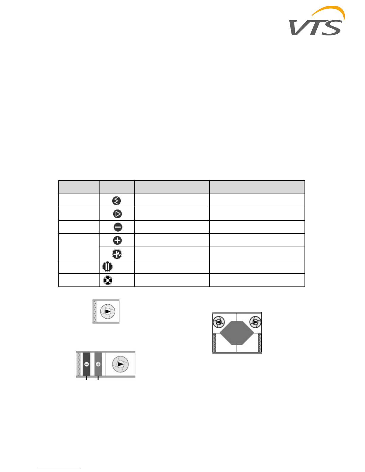
There is a list of symbols and functions of air handling units:
Table 1 Functions coding
Symbol Graphic Function Options of functions
F
Air filtration M5,F7, F9
V
Ventilation
C
Cooling
(hydronic or dx)
Rows: 2, 4, 6
H
Heating
(hydronic)
Hot Water – rows: 1, 2, 3, 4
Heating
(electric)
Draw–through electric heater
S
Silencer Standard size
P
Recovery with counter–flow heat
exchangers
Standard size
Fig.1. Examples of suspended AHUs type VVS010s –015s functional configurations
Exhaust–air AHU
Supply–air AHUU
AHU with cross–flow exchanger
OMM–VTS–ver.1.6 (05.2018)
www.vtsgroup.us 8
3 General Information
VVS suspended units are manufactured in
sections designed for assembly in suspended
configurations. All VVS AHUs are intended for
indoor use, for cooperation with a duct
ventilation system. The ventilation duct system
is understood as a net of ventilating ducts. Thus
access to the rotating parts of the unit (a fan’s
rotor) is impeded from both positive and
negative pressure side of the unit.
The majority of AHU’s configuration is available
in left–hand and right–hand execution (example
in the fig.2). The version of the unit is
determined by the flow direction of the air
against the piping side of the unit (the side
where the coils connection pipes are located).
In case of supply–exhaust units the version is
determined by the flow direction of the air in the
supply section.
Fig. 2 Versions of the VVS010s–015s AHU – Right–hand version
By default the VVS010s–015s AHU is
positioned horizontal–suspended. In case of
some functional set it is also possible to set the
unit in a vertical position – on a wall.
Basic heat recovery unit components consist of
a counter flow heat exchanger, condensate
drain pan, filters, direct drive fan assemblies
(fig.3).
Air–flow
direction
OMM–VTS–ver.1.6 (05.2018)
www.vtsgroup.us 9
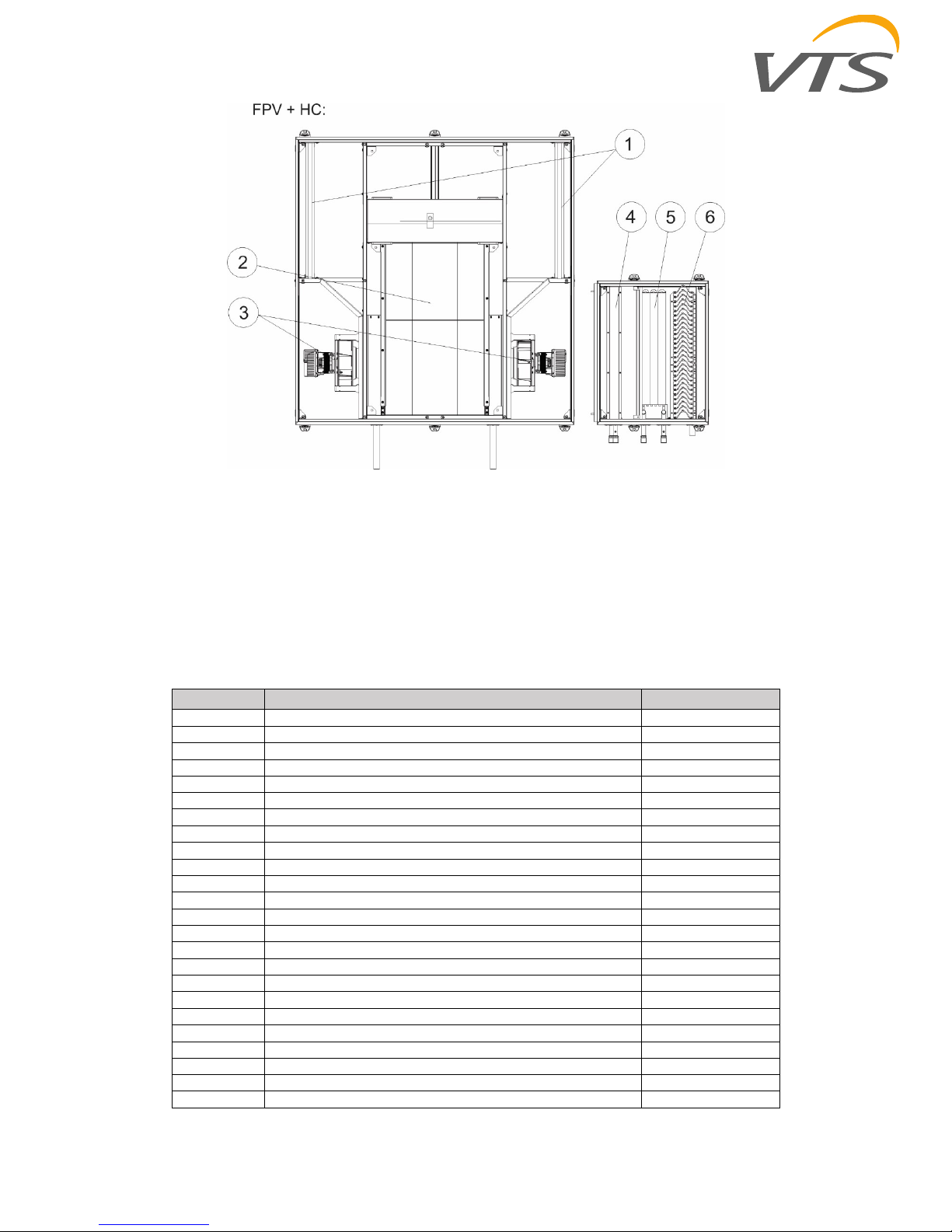
Fig.3. Example of the basic supply–exhaust unit (FPV) with additional coils section (HC):
1 – filters, 2 – counter–flow heat exchanger, 3 – fans, 4 – heater, 5 – cooler, 6 – droplet eliminator
VVS010s–015s AHUs consist of freely
configurable sections. One can find recovery
section with very high efficiency counter–flow
plate heat exchanger, filters (M5 and F7) and
fans with EC motors. For that main unit is
possible to choose additional section with
heater (water and electric, cooler (water and
Freon), secondary filter and silencer. The
functions like filtration, heating and cooling are
also available installed in one section with a fan
(tab.2, fig.4).
Table 2 Functionality and length of the sections
Function Name L [mm]
F Filter 180
H Water heater 180
HE Electric heater 370
C Cooler (water or freon) 370
C_de Cooler with droplet eliminator 600
HC Water heater and cooler 460
HC_de Water heater and cooler with droplet eliminator 600
HEC Electric heater and cooler 740
HEC_de Electric heater and cooler with droplet eliminator 860
FPV Plate heat exchanger, filters and fans 1500
V Fan 460
FV Filter and fan 740
FHV Filter, water heater and fan 740
FHEV Filter, electrc heater and fan 1030
FCV Filter, cooler and fan 860/1030*
FCV_de Filter, cooler with droplet eliminator and fan 1030
FHCV Filter, water heater, cooler and fan 1030
FHCV_de Filter, water heater, cooler with droplet eliminator and fan 1230
FHECV Filter, electric heater, cooler and fan 1230
FHECV_de Filter, electric heater, cooler with droplet eliminator and fan 1380
S Silencer L=370 370
S Silencer L=740 740
E Empty section L=370 370
E Empty section L=740 740
OMM–VTS–ver.1.6 (05.2018)
www.vtsgroup.us 10
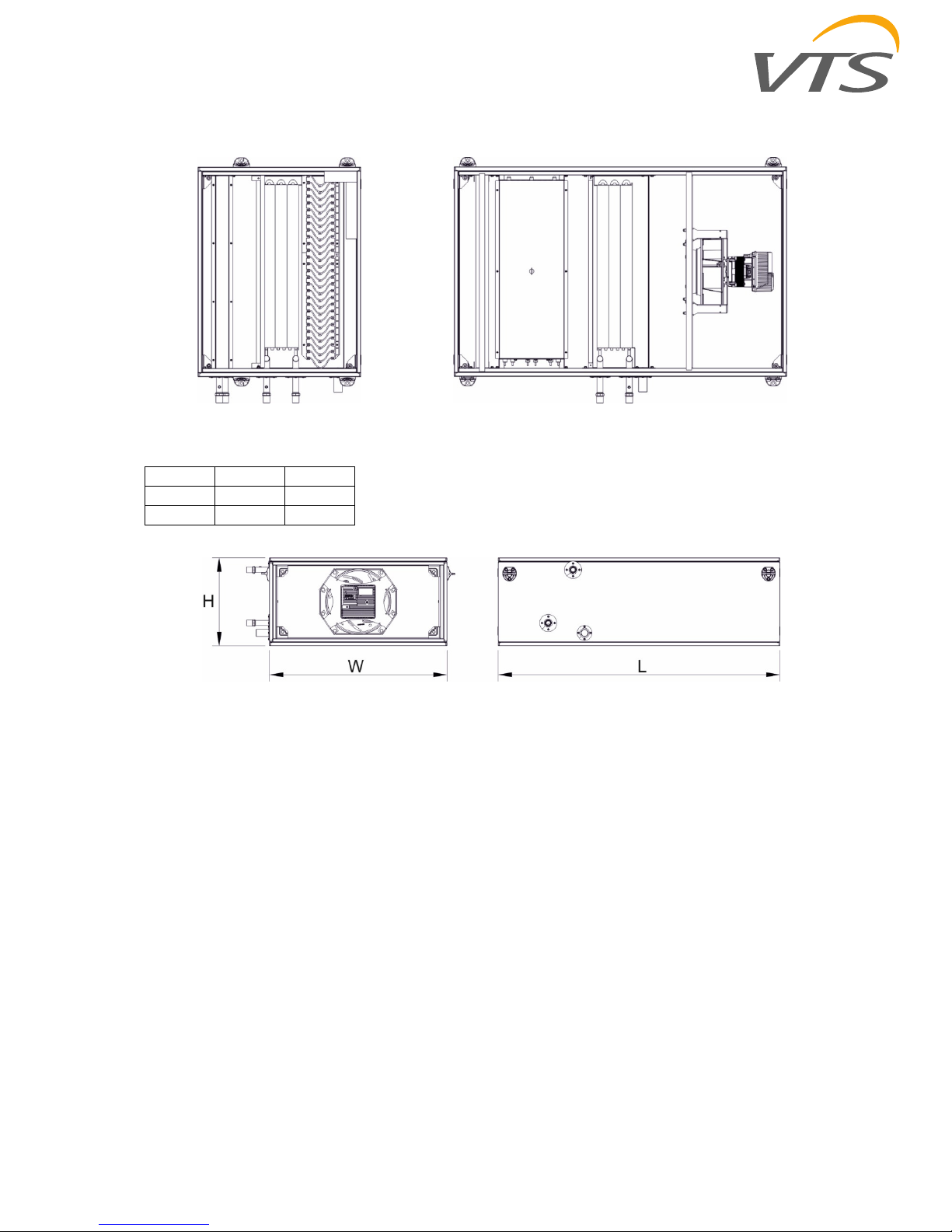
Fig.4. Example of the sections
Fig.5. Dimension of the section
AHU size
W [mm] H [mm]
VVS010s
575 380
VVS015s
775 380
HC:
FHEV:

OMM–VTS–ver.1.6 (05.2018)
www.vtsgroup.us 11
4 Pre–Installation
4.1 Transport and storage
The air handling units are packaged for easy
handling and storage on the job site. Upon
delivery, inspect all components for possible
shipping damage. See the “Receiving
Checklist” section for detailed instructions. VTS
recommends leaving units and accessories in
their shipping packages/skids for protection and
handling ease until installation.
NOTICE! Packages onsite must be stored
on hardened, dry and protected against
any precipitation place.
Packages containing AHU elements
should be stored away from places where
operate mechanical devices (vehicles,
cranes and other construction machinery).
They should be stored in places where
they will not be subject to any mechanical
damages, humidity, aggressive chemical
agents, fluids, dusts and other external
agents which may deteriorate their
condition.
The AHUs have to be transported in their
working position and they shall not be stored
one on the other.
The units and their components should be
stored in rooms characterized by the following
conditions: relative humidity: φ < 80 % at t
(temperature) = 20ºC ambient temperature: –
40ºC < t < +60ºC – the devices should be out of
the reach of any caustic dust, gas or steam as
well as any other chemical substances which
may have pro–corrosive influence on the unit
and its components.
While storing the unit, its plastic packaging must
be unsealed.
4.1.1 Receiving Checklist
Complete the following checklist immediately after receiving unit shipment to detect possible shipping
damage.
Inspect individual crates before accepting.
Check for rattles, bent crates corners, or
other visible indications of shipping
damage.
If a unit appears damaged, inspect it
immediately before accepting the
shipment. Make specific notations
concerning the damage on the freight bill.
Do not refuse delivery.
Inspect the unit for concealed damage
before it is stored and as soon as possible
after delivery. Report concealed damage to
the freight line within the allotted time after
delivery. Check with the carrier for their
allotted time to submit a claim.
Do not move damaged material from the
receiving location. It is the receiver’s
responsibility to provide reasonable
evidence that concealed damage did not
occur after delivery.
Do not continue unpacking the shipment if
it appears damaged. Retain all internal
packing, cartons, and crate. Take photos of
damaged material if possible.
Notify the carrier’s terminal of the damage
immediately by phone and mail. Request
an immediate joint inspection of the
damage by the carrier and consignee.
Notify your VTS representative of the
damage and arrange for repair. Have the
carrier inspect the damage before making
any repairs to the unit.
Compare the electrical data on the unit
nameplate with the ordering and shipping
information to verify the correct unit is
received.
NOTICE!
Any damages caused by improper transportation, unloading or storage are not covered by the
Warrantee and any claims laid by way of aforementioned issues will not be examined by VTS.

OMM–VTS–ver.1.6 (05.2018)
www.vtsgroup.us 12
4.2 Installation Preparation
The units are designed for suspended
installation. Suspension of units requires
external rigging which shall be field–mounted.
Ensure the ceiling opening is large enough for
unit installation and maintenance requirements.
By default the AHU is positioned horizontal–
suspended and also it is possible to set the unit
in a vertical position – on a wall.
NOTICE! It is not acceptable to install the
VVS010s and VVS015s AHU horizontally
on a wall (sideways – in parallel to the
ceiling). In case of vertical assembly it is
important that the exchanger’s inlet and
outlet connections were positioned
horizontally. Air flow must be directed
vertically. Devices equipped with an
electric heater cannot be mounted
vertically.
4.2.1 Unit Location Recommendations
When selecting and preparing the unit installation location, consider the following recommendations.
1. Consider the unit weight. Reference the unit weight on the unit nameplate
2. Allow sufficient space for the recommended clearances, access panel removal, and maintenance
access.
3. The installer must provide external rigging for ceiling mounted units.
4. All units must be installed level.
5. Coil piping and condensate drain requirements must be considered.
Allow room for proper ductwork and electrical connections. Support all piping and ductwork
independently of unit to prevent excess noise and vibration.
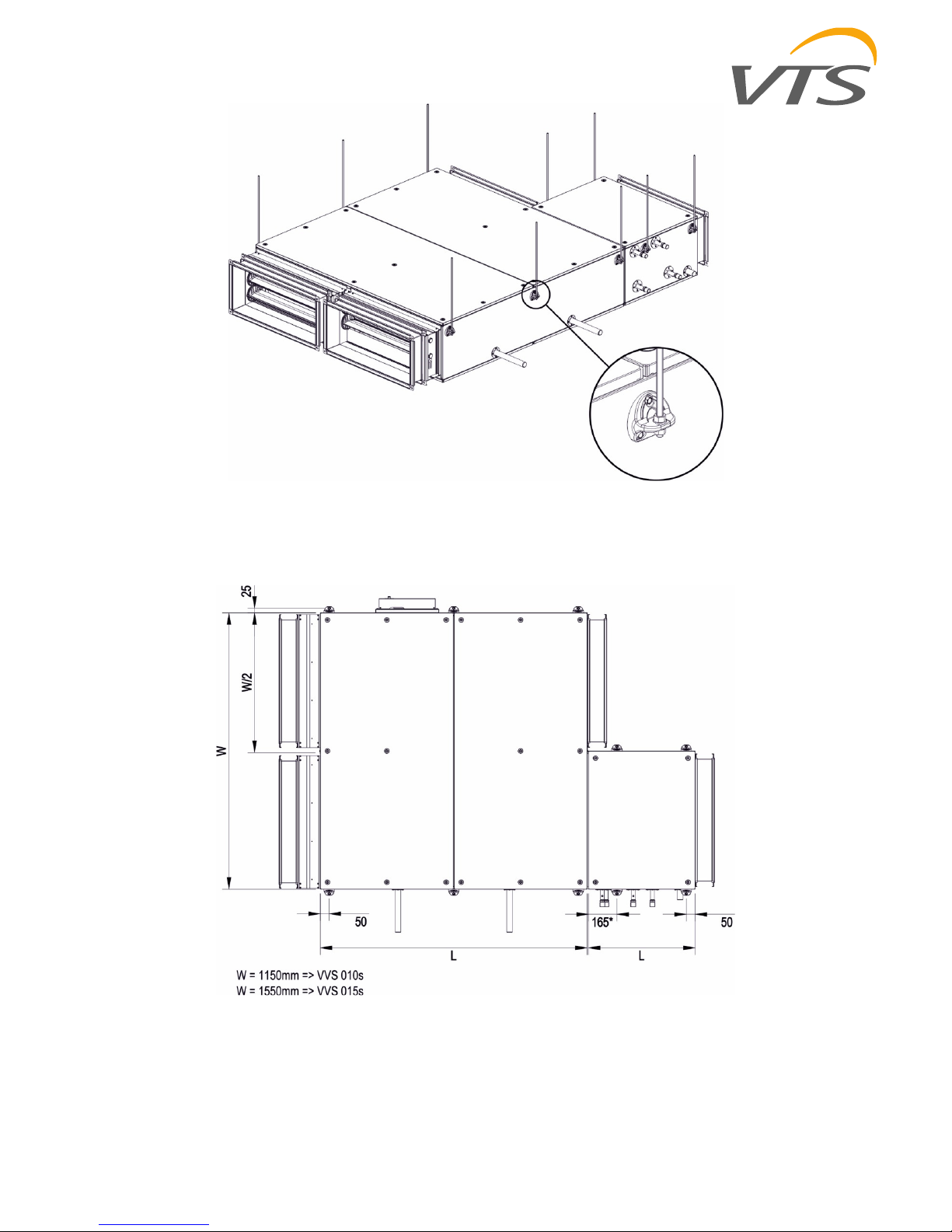
4.2.2 Assembly in suspended position
Suspension of an AHU as a part of ventilation
ducts is carried out using suspension grips
which are located at a side of each AHU section
(fig.8). Application of M8 screwed rods
facilitates and speeds up suspension and
leveling of each AHU section (the screwed rods
are not included).
NOTICE! It is recommended to use vibro
absorber to suspend the units, to reduce
the vibrations transmitted to the supporting
structure.
OMM–VTS–ver.1.6 (05.2018) 13
Fig.6 Example of suspending the AHU sections
Fig.7 Suspension grips arrangement
OMM–VTS–ver.1.6 (05.2018)
www.vtsgroup.us 14
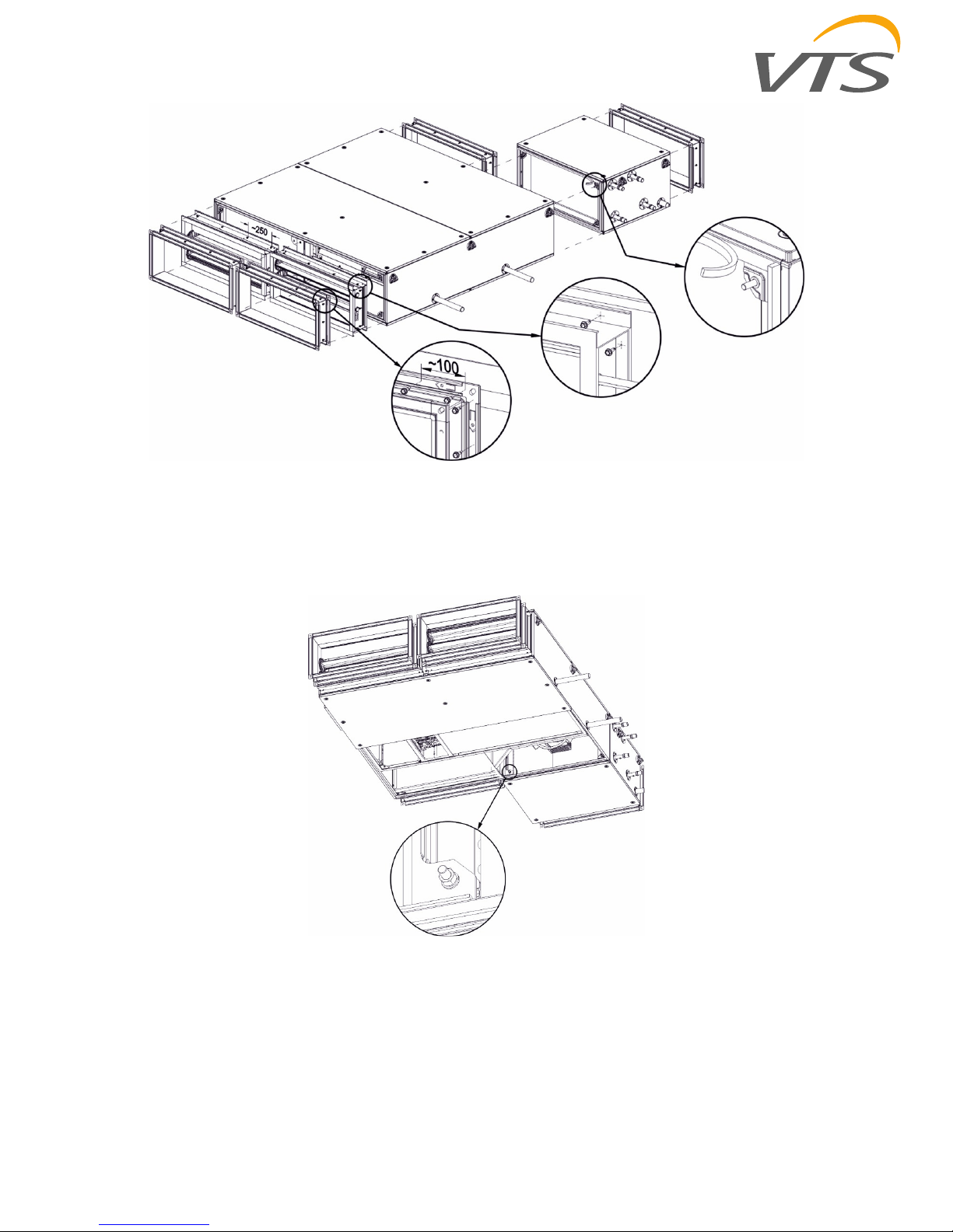
Fig.8a Joining sections and optional elements assembly.
Fig.8b Joining sections and optional elements assembly.
OMM–VTS–ver.1.6 (05.2018)
www.vtsgroup.us 15
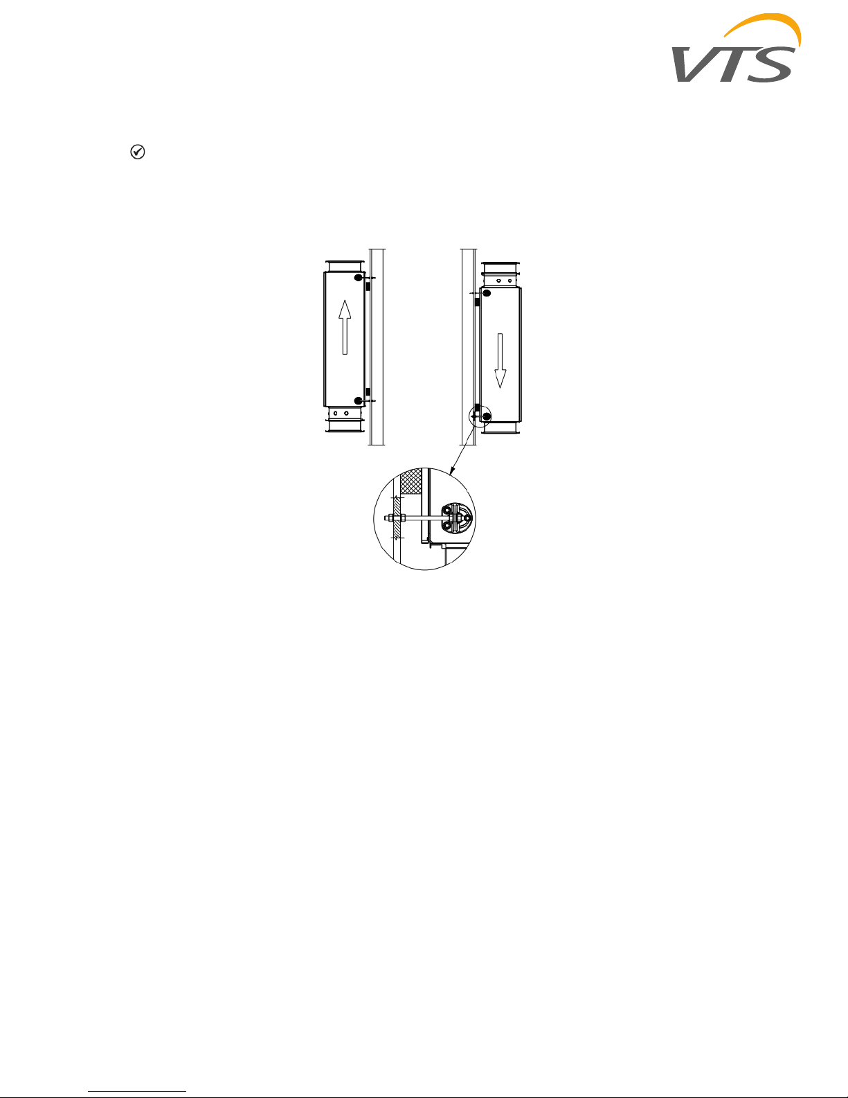
4.2.3 Setting in vertical position
NOTICE! This position is not allowed for the AHUs containing the cooling or electric heating section
as well as the cross–flow exchanger section.
Setting in this position requires a rigid framework fixed to a wall. The AHU should be mounted to the
framework with fixing grips and M8 screws.
Fig.9 Example of setting AHU in vertical position
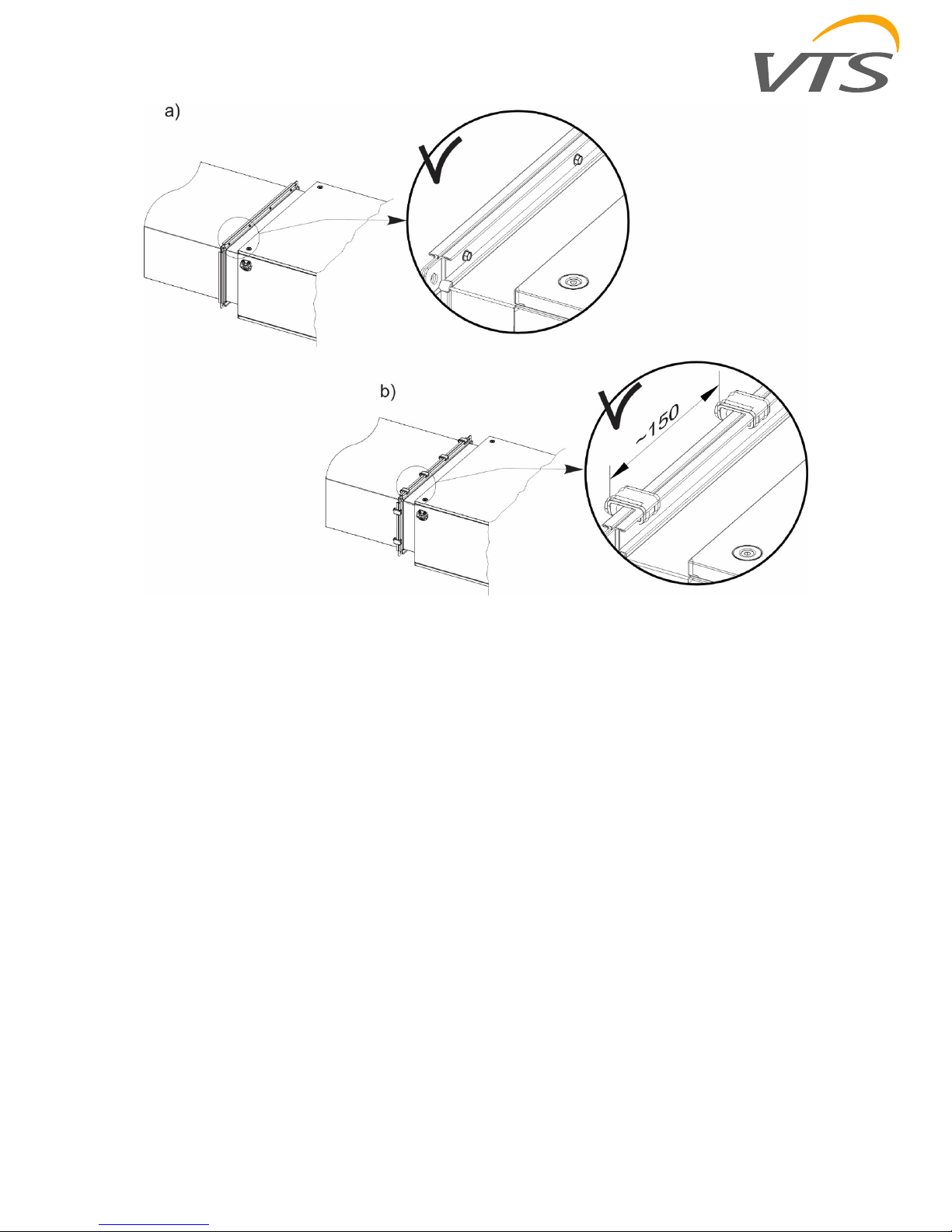
4.2.4 Connecting the ventilation ducts
The ventilation ducts should be connected to
the AHU with the flexible connections (optional
accessory) which suppress vibrations of the unit
and level the coaxial deflection of the duct and
the AHU outlets. Flexible connections are
equipped with flanges with sealing. The flexible
flanges should be connect with ducts with using
drilling screws (Fig.12a) or additional clamping
elements (Fig. 12b). Materials to connect ducts
are not supplied as standard delivery.
Appropriate operation of the flexible connection
occurs if it is stretched to about 110 mm.
The ducts connected to the AHU have to be
suspended or underpinned with dedicated
support elements.
Conducting the ducts with the fittings should be
done in a way to eliminate possible increase of
noise level in the ventilation system.
OMM–VTS–ver.1.6 (05.2018)
www.vtsgroup.us 16
Fig.10 Duct’s connection rules
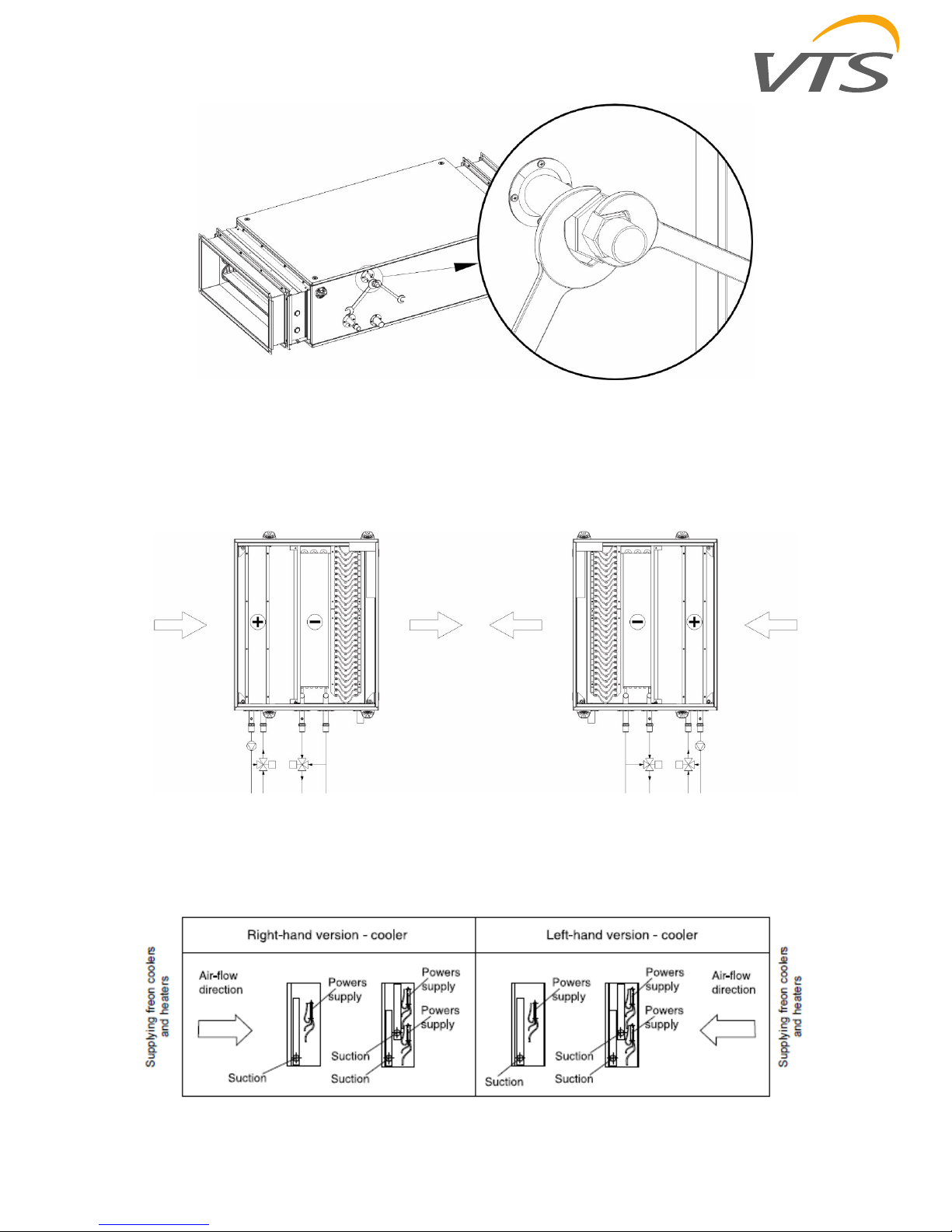
4.2.5 Connection of heaters and coolers
Connection of the exchangers should be carried
out so as not to allow for stresses which may
result in mechanical damages or leakage. The
pipeline weight and thermal stresses cannot be
passed onto the exchanger's connections.
Depending on a local conditions please use the
compensation at the supply and return of the
pipeline system, in order to level the pipeline's
linear expansion. During assembly of the supply
system to the exchangers equipped with the
screwed connections, counter the exchanger's
connection with additional wrench (fig.11).
The supply system should be planned so as it
does not collide with the other AHU sections.
Applied method of connecting the exchangers
with the supply system should allow for an easy
pipeline disassemble in order to remove the
exchanger from the AHU, during maintenance
and service operations.
OMM–VTS–ver.1.6 (05.2018)
www.vtsgroup.us 17
Fig.11. Securing the screwed connections of the exchanger
Supply and return exchanger connections should be connected so as the exchanger operates in a
countercurrent way. Stream wise operation results in lower average temperature difference, influencing
the exchanger’s performance.
Examples of connecting supply and return pipelines for various AHU versions shown in the fig.12
Fig.12. Examples of feeding water exchangers
Connecting the freon cooler to the supply system with a refrigerating unit should be done by a qualified
cooling system specialist in accordance with the regulations concerning the freon–driven cooling
devices.
Fig. 13 Supplying freon coolers and heaters
OMM–VTS–ver.1.6 (05.2018)
www.vtsgroup.us 18
NOTICE: The DX coils have sweat connections. When brazing or welding piping: avoid exposing
piping components to high heat when making sweat connections and protect the closest valve to
the connection with a wet rag.
NOTICE: Do not release refrigerant to the atmosphere! If adding or removing refrigerant is
required, the service technician must comply with all federal, state, and local laws.
NOTICE: Secure the coil against frost on the coil
NOTICE: To ensure satisfactory operation of DX coolers the coolers should be connected to the
refrigerant system in accordance with all relevant regulations, rules and the best practice for that
area.
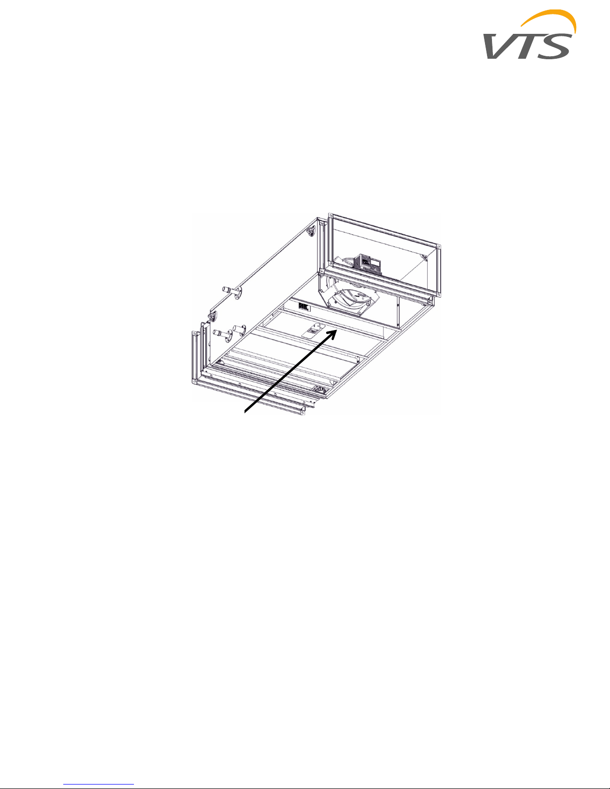
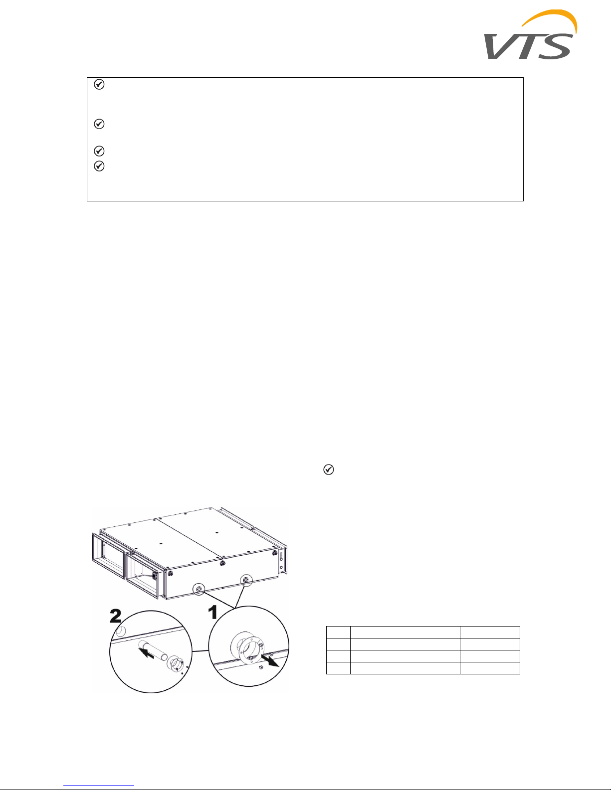
4.2.6 Draining out condensate
The outlet condensate connections, led outside
the AHU's casing are assembled in the drain
plates of coolers, counter–flow heat exchangers
(the diameter of drain pan connection pipe is
32mm).
To avoid damage drain pipe of the counter-flow
heat exchanger section during transportation,
they are not installed and attached separately in
the package.
To mount the drain pipe one should unscrew the
drilling screws and disassembly header
connection glands (magnification (1) in the the
below figure), install the pipe on the drain pan
connection inside the casing and assembly
bach the header glands (2).
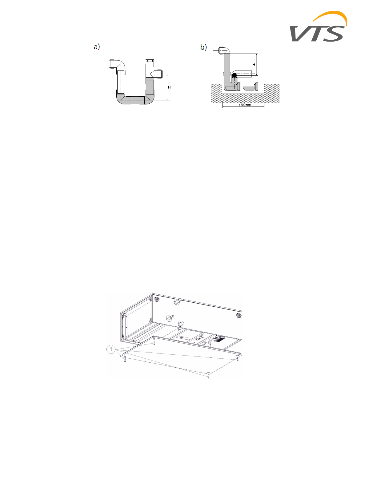
Siphons, which are designed to drain out
condensed water from the exchangers at
different pressure of the section and
environment, should be connected to the drain
connections.
For proper drainage of condensate from the
unit, the siphon on the drain pan connection
pipe must be installed in the AHU sections,
where negative pressure occurs. Drain siphons
or siphon parts are not supplied as standard
delivery. There is no need to apply drain
siphons in section with overpressure. In order to
minimize air blow–by, you can use a siphon on
the system draining out condensate,
assembling the siphon made in accordance with
fig. 14 and table 3.
Siphons usable „H" height depends on the
pressure difference between the AHU section,
where condensate is drained from during
operation and the ambient pressure. „H"
dimension is provided in mm and must be
higher than the pressure difference expressed
in mmH2O.
NOTICE! Due to various pressure
difference values which are present in various
AHU sections during operation it is not
allowable to connect several condensate outlets
into one siphon.
It is allowable to join together siphons of various
sections with one drain interceptor provided that
the interceptor will be equipped with air–
escape. Before starting the AHU, fill the siphon
with water. In case of cold environment, insulate
the water drain system and eventually apply
suitable heating system.
Table 3. Siphons' operational height
No. Total fan's pressure [Pa] Size H [mm]
1. < 600 60
2. 600–1000 100
3. 1000–1400 140
OMM–VTS–ver.1.6 (05.2018) 19
Fig.14 Types of siphons
4.2.7 Electric connection
Connection of electric AHU elements should be
carried out by qualified personnel and should be
done in accordance with any standards and
regulations being in force in a country where the
unit is installed. Cross section and type of
cables (e.g. shielded cable) feeding individual
functional segments should be selected basing
on nominal current and specific operation
conditions (e.g. ambient temperature, way of
cabling, distance from the power supply).
Before starting connecting power supply, check
conformity of the voltage and frequency of a
supply network with the data shown on the
device's rating plate. Permissible fluctuation of
the supply voltage and its frequency to the
values shown on the rating plate is ±5%. If
discrepancy exists, the device cannot be
connected.
4.3 Service Access
The AHU shall be installed so that the
connections of any related systems (ventilation
ducts, pipelines, cabling, etc.) do not collide with
the inspection panels.
Access to the internal elements of the units is
possible by opening inspection panels. To
remove the panel, unscrew few screws (1)
fig.15 (numbers depend on the size of the
section).
Fig.15 Removing inspection panel
OMM–VTS–ver.1.6 (05.2018)
www.vtsgroup.us 20
4.3.1 Skid Removal
The unit ships on skids that provide forklift
locations from the front or rear. The skid allows
easy maneuverability of the unit during storage
and transportation. Remove the skids before
placing the unit in its permanent location.
Remove the skids using a forklift or jack. Lift one
end of the unit off of the skids.
4.4 AHU components
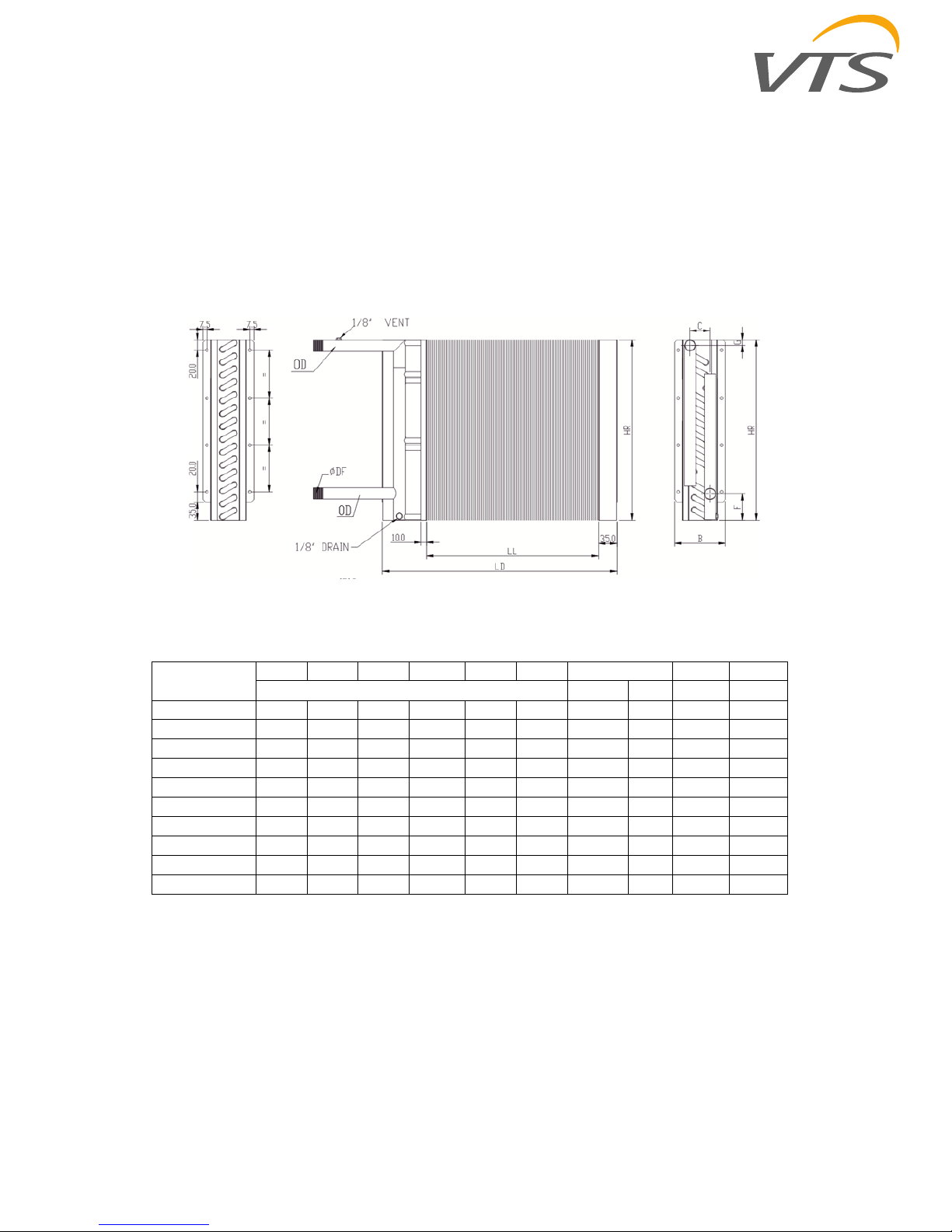
4.4.1 Hydronic coil exchangers
Fig. 16 Dimensions of hydronic coil exchangers
Table 4 Dimensions of hydronic coil exchangers of (Fig. 18)
VSC Type
LL HR B C F G OD Weight Volume
[mm] [mm] [in] [kg] dm3
VVS010s WCL1 403 300 74,7 32 54 15 22 3/4" 2,4 0,56
VVS010s WCL2 403 300 96,3 32 54 15 22 3/4" 3,1 0,94
VVS010s WCL3 403 300 118,0 43 54 15 22 3/4" 3,9 1,31
VVS010s WCL4 403 300 139,6 65 54 15 22 3/4" 4,9 1,69
VVS010s WCL6 403 300 182,9 108 54 15 22 3/4" 6,7 2,43
VVS015s WCL1 603 300 74,7 32 54 15 22 3/4" 3,2 0,73
VVS015s WCL2 603 300 96,3 32 54 15 22 3/4" 4,3 1,27
VVS015s WCL3 603 300 118,0 43 54 15 22 3/4" 5,4 1,82
VVS015s WCL4 603 300 139,6 65 54 15 22 3/4" 7,0 2,36
VVS015s WCL6 603 300 182,9 108 54 15 22 3/4" 9,6 3,44
OMM–VTS–ver.1.6 (05.2018)
www.vtsgroup.us 21
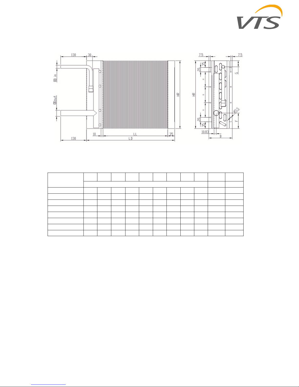
4.4.2 DX Coils
Fig. 17 DX coil drawing
Table 5 Dimensions of DX coils (Fig. 20)
VSC Type
LL HR B C E G F
OD
in
OD
out
Weight Volume
[mm] [kg] [dm3]
VVS010s DX 2–1 403 300 96,3 32 75 19 80 16 28 3,0 0,88
VVS010s DX 3–1 403 300 118,0 43 75 19 80 16 28 3,8 1,24
VVS010s DX 4–1 403 300 139,6 65 75 19 80 16 28 4,7 1,64
VVS010s DX 6–1 403 300 182,9 108 75 19 80 16 28 6,9 2,34
VVS015s DX 2–1 603 300 96,3 32 75 19 80 16 28 4,2 1,21
VVS015s DX 3–1 603 300 118,0 43 75 19 80 16 28 5,4 1,73
VVS015s DX 4–1 603 300 139,6 65 75 19 80 16 28 7,1 2,26
VVS015s DX 6–1 603 300 182,9 108 75 19 80 16 28 9,4 3,38
 Loading...