

Technical documentation
Check us on
WG.US-Rev.2.8 (09.2020)
WING W100-200
WING E100-200
WING C100-200
EN

WING W100-200
WING E100-200
WING C100-200
1. Table of content
1. INTRODUCTION ...................................................................................................................... 3
1.1. PRECAUTIONS, REQUIREMENTS, RECOMMENDATIONS ........................................ 3
1.2. TRANSPORT ................................................................................................................. 3
1.3. INITIAL STEPS TAKEN BEFORE THE INSTALLATION ................................................. 3
2. STRUCTURE, INTENDED USE, PRINCIPLE OF OPERATION ............................................ 3
2.1. INTENDED USE ............................................................................................................ 3
2.2. PRINCIPLE OF OPERATION......................................................................................... 3
2.3. STRUCTURE (WING 100-200) ...................................................................................... 4
2.4. OVERALL DIMENSIONS (WING E, W, C 100-200) ........................................................ 4
3. MOUNTING .......................................................................................................................... 4
3.1. ASSEMBLY/ DISASSEMBLY OF JUNCTION BOX COVER .......................................... 5
3.2. INSTALLATION OF DEVICE ......................................................................................... 5
3.2.1. HORIZONTAL INSTALLATION BY MEANS OF HOLDERS. ................................... 6
3.2.2. VERTICAL ASSEMBLY USING INSTALATION HOLDERS. .................................... 7
3.3. ASSEMBLY AND INSTALLATION GUIDELINES ........................................................... 7
4. ELEMENTS OF CONTTROLS. ........................................................................................... 11
5. START-UP, OPERATION, MAINTENANCE ........................................................................ 11
5.1. START-UP/PUTTING INTO OPERATION ................................................................... 11
5.2. OPERATION AND MAINTENANCE .............................................................................. 11
6. SERVICING ........................................................................................................................ 12
6.1. PROCEDURE IN CASE OF MALFUNCTION ............................................................... 12
6.2. COMPLAINT PROCEDURE ......................................................................................... 12
7. INDUSTRIAL SAFETY INSTRUCTION ............................................................................... 12
8. TECHNICAL SPECIFICATION ............................................................................................. 13
8.1. WATER AIR CURTAIN – WING W100-200 .................................................................. 13
8.2. ELECTRIC AIR CURTAIN – WING E100-200 ............................................................... 14
8.3. WING C100-200 – COLD AIR CURTAIN ...................................................................... 14
9. ELECTRICAL DIAGRAMS .................................................................................................. 15
9.1. Electrical diagram of WING W100-200-EC – 1~240V ...................................................... 15
3
1. INTRODUCTION
1.1. PRECAUTIONS, REQUIREMENTS, RECOMMENDATIONS
Detailed analysis of this documentation, as well as assembly and use of equipment, according to the descriptions contained th erein, and following all safety requirements, is the basis for the
correct and safe operation of the device. Any other use that contradicts this instruction may cause accidents with serious consequences. Unauthorized personnel should have limited access
to the device, while the personnel should be properly trained. The term operational personnel ref ers to people, who, as the result of completed training, own experience and knowledge of
important standards, documentation and provisions, concerning safety and working conditions, have been authorized to carry out necessary work and are able to recognize potential hazards
and avoid them. This technical documentation must be delivered together with the device. The documentation contains information concerning all possible configurations of air curtains.
Examples of air curtain assembly and installation, as well as activation, use, repair and maintenance. Provided that the device is operated according to the intended use, this documentation
contains a sufficient number of ins tructions, required by the qualified personnel. The documentation should be placed n ear the device and be readily available to the service team. The
manufacturer reserves the right to introduce changes to the instruction, as well as changes to the device that affect its operation, without prior notice. VTS shall bear no responsibility for ongoing maintenance, inspections, programming of equipment and damage, caused by standstills of equipment related to the waitin g for warranty services, all and any damage related to the
Client’s property, other than the device in question, as well as malfunctions that result from incorrect installation or improper use of the device.
WING air curtains are intended for indoor installation only.
DO NOT COVER
WARNING: To avoid overheating - do not cover the device!
1.2. TRANSPORT
Prior to the installing and taking the device out of the cardboard box, it is required to check whether the cardboard box has not been damaged in any way and/or the adhesive tape (in stalled
at the company) has not been broken off or cut. It is recommended to check whether the device’s casing has not been damaged in transport. Should any of the above situation occur, please
contact us through telephone or e-mail: Tel. +1 470-809-6811, email: america@vtsgroup.com, fax: +1 470-809-6815.
The device should be transported by two people. Use appropriate tools, when transporting the device, so as to avoid the damaging of goods and potential hazard to health.
1.3. INITIAL STEPS TAKEN BEFORE THE INSTALLATION
Record the serial number of the device on the warranty card, prior to the commencement of the installation process. It is required to properly fill-in the warranty card, once the installation is
complete. Prior to the commencing of any installation or maintenance work, it is required to disconnect power supply and protect it against unintentional activation.
Installation and start-up should be performed by qualified personnel, according to the guidelines provided in this manual. The order of
installation steps are as follows:
• Mount the device in its intended operation place
• Perform the hydraulic connection, check connections for tightness and vent the system
• Perform the electrical connection
• Make sure the device is correctly connected (according to the diagram)
• In the case of an electrical curtain, vacuum the heaters to avoid the unpleasant smell of burning dust
• Turn the power on and start the device.
2. STRUCTURE, INTENDED USE, PRINCIPLE OF OPERATION
2.1. INTENDED USE
For the convenience of users as well as different types of installations in commercial and industrial facilities we have designed an air curtain in three different options and three sizes:
● a WING W100 240/1/60 curtain 42in wide with a water heater (13.6-58MBH, 1089 CFM)
● a WING E100 (models: WING E100 240/1/60, WING E100 240/3/60, WING E100 480/3/60) curtain 42in wide with electric heaters (6.8/13.6/20.5 MBH, 1089 CFM)
● a WING C100 240/1/60 curtain 42in wide (1107 CFM)
● a WING W150 240/1/60 curtain 62in wide with a water heater (34.1- 109 MBH, 1825 CFM)
● a WING E150 (models: WING E10 240/3/60, WING E150 480/3/60) curtain 62in wide with electric heaters (13.6/27.3/40.9 MBH, 1854 CFM)
● a WING C150 240/1/60 curtain 62in wide (1884 CFM)
● a WING W200 240/1/60 curtain 82in wide with a water heater (58- 160 CFM, 2590 CFM)
● a WING E200 (models: WING E200 240/3/60, WING E200 480/3/60) curtain 82in wide with electric heaters (20.5/30.7/51 MBH, 2649 CFM)
● a WING C200 240/1/60 curtain 82in wide (2708 CFM)
The above sizes of curtains are available with three options of voltage supply: 1x240VAC, 3x240VAC, 3x480VAC
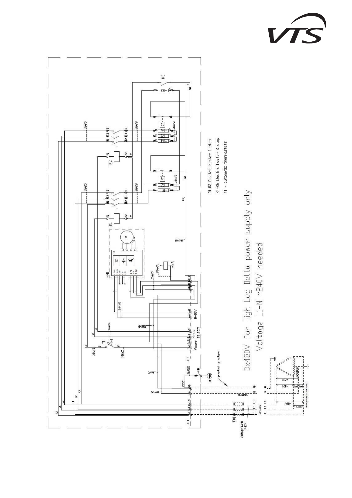
! Voltage supply 1x240VAC is available only for the curtains WING E100 240/1/60, all WING W and all WING C
! Caution
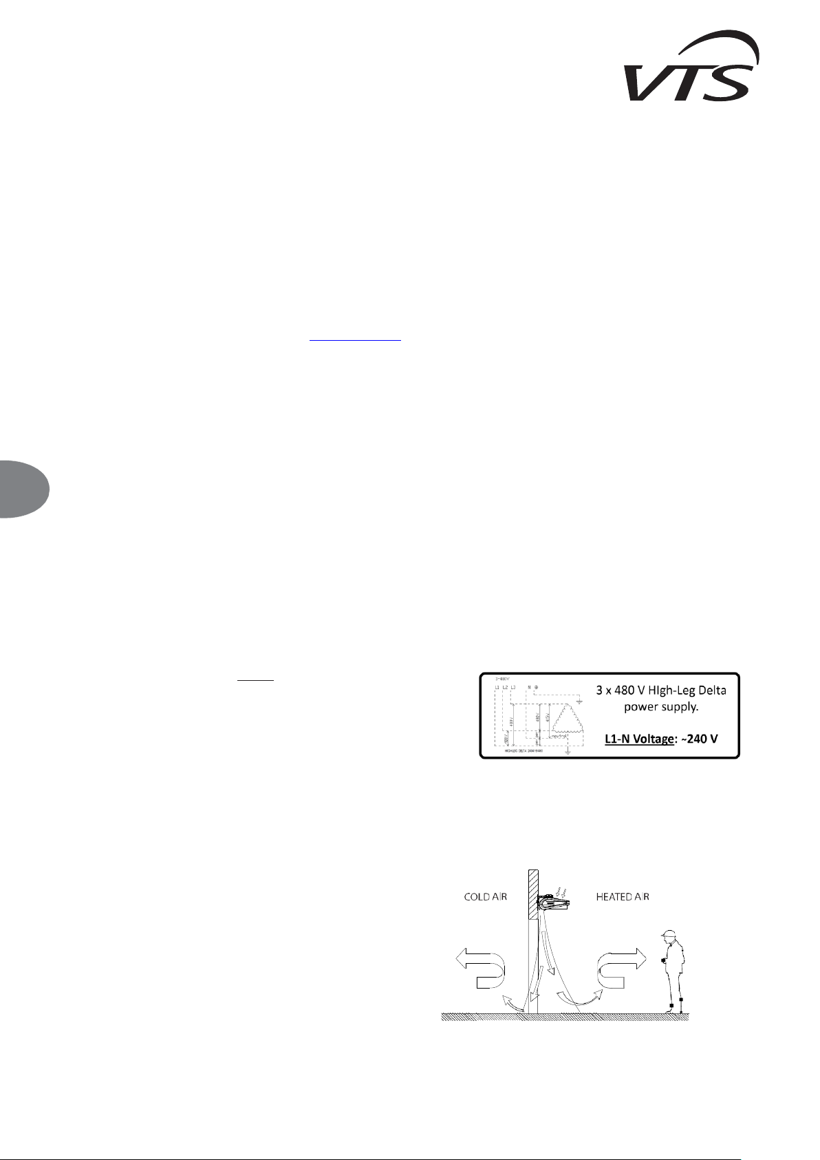
The following models of WING air curtains must be supplied using High-Leg Delta supplying
circuit:
• WING E100 480/3/60 Air Curtain
• WING E150 480/3/60 Air Curtain
• WING E200 480/3/60 Air Curtain
For these models, the L1-N voltage will must be 240 VAC.
The use of the WING air curtain enables the leaving of the room door open, regardless of weather conditions, thus providing a protective barrier. The curtain also enables a simultaneous keeping of
the required heating comfort inside the room/facility. T he modern design of the WING air curtain is a result of its wide range of application. The places in which it is possible to install the device include:
malls, office buildings, supermarkets, cinema complexes, as well as shops, store-rooms, manufacturing facilities or warehouse rooms. Please notice that the use of an air curtain not only provides a
protective barrier, but also it is an additional heat source in the room. APPLICATION: warehouse rooms, warehouses, sports facilities, supermarkets, religious buildings, hotels, clinics, pharmacies,
hospitals, office buildings, manufacturing facilities. PRIMARY ADVANTAGES: protection of climatic conditions in the room, reduction of heating/cooling costs, universal size, ability to work both in
vertical and horizontal position; simple, quick and intuitive assembly.
2.2. PRINCIPLE OF OPERATION
WING W100-200 - heating medium, for example hot heating water, returns
heat through a heat exchanger with a wide heat-exchange surface, thus
providing high heating output (13.6-160 MBH). A transverse fan (518-2590
CFM) sucks in the air in the room, and pumps it through the heat exchanger,
back into the room. The jet of warm air is directed downstream at high
velocity, thus providing an air barrier.
WING E100-200 - electric heaters (6.8-51.2 MBH) heat up, as a result of the
flowing of electric current, and return the heat to the air; the air is blown off
through the fan, which sucks in the air in the room. A jet of warm air is directed
downstream at high velocity, thus providing an air barrier.
EN
WING W100-200
WING E100-200
WING C100-200
4
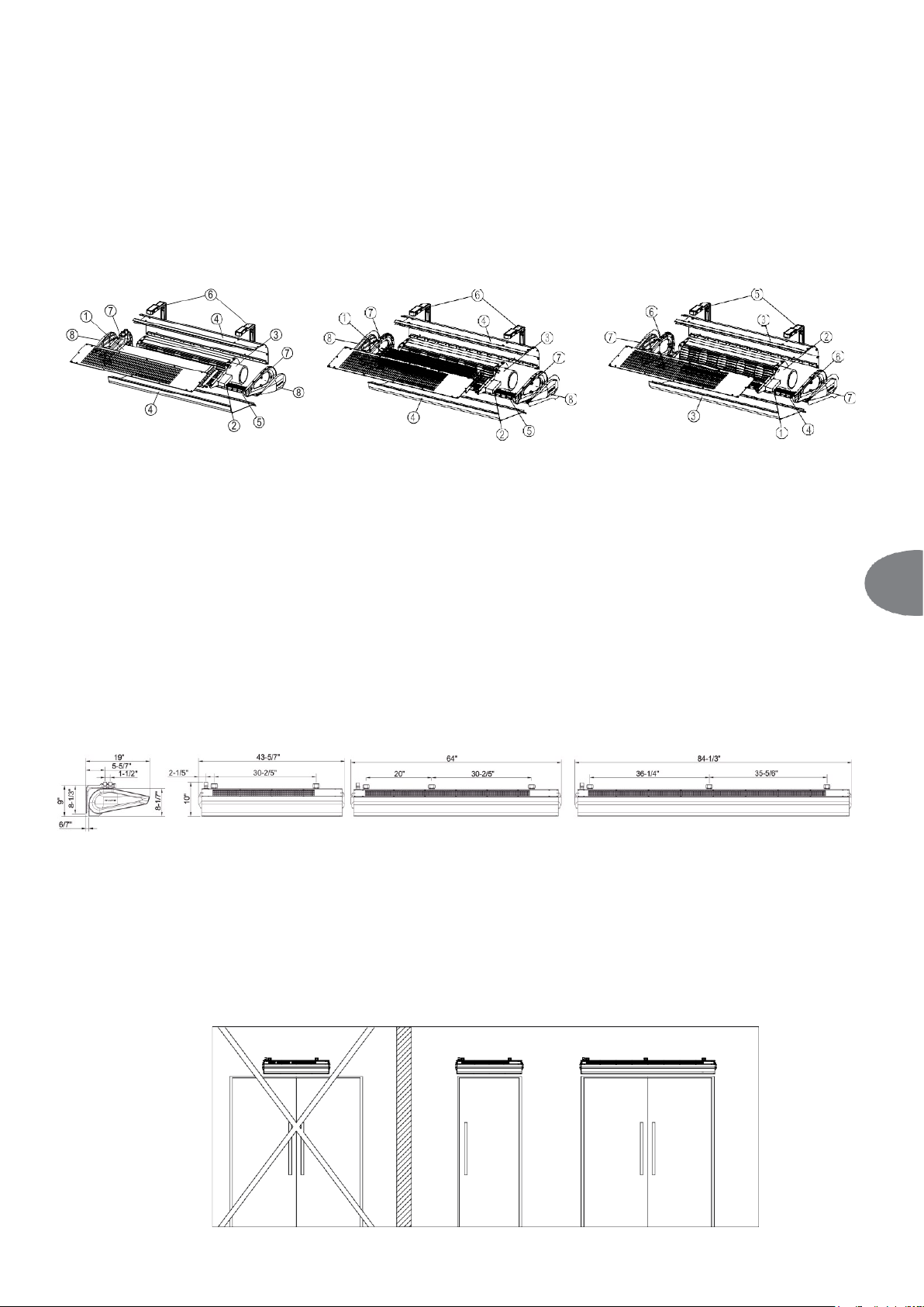
2.3. STRUCTURE (WING 100-200)
WING W100-200 – WATER AIR CURTAIN
1. Heat exchanger
2. Control system
3. Transverse fan
4. Casing
5. Outlet grille
6. Assembly jigs
7. Side cover
8. Side cap
WING E100-200 – ELECTRIC AIR CURTAIN
1. Electric heaters
2. Control system
3. Transverse fan
4. Casing
5. Outlet grille
6. Assembly jigs
7. Side cover
8. Side cap
WING C100-200 – COLD AIR CURTAIN
1. Control system
2. Transverse fan
3. Casing
4. Outlet grille
5. Assembly jigs
6. Side cover
7. Side cap
1. HEAT EXCHANGER – WATER HEATER: Maximum parameters of the heating agent for the heat exchanger are: 200°F, 232 psi. The aluminum and copper construction consists of copper
pipes of the coil and aluminum lamellae. The connection manifold (¾” male thread) is situated in the upper part of the housing. An optimally selected water exchanger was adapted to work in
three positions: horizontally and vertically, with stub pipes facing upwards and downwards. Appropriate lead of hydraulic connections makes it possible for the curtain to be assembled directly by
the wall as close to the door frame as possible. The air curtain with a water heater generates power from 13.6 to 160 MBH.
ELECTRIC HEATER: each electrical curtain consists of 6 electrical heaters of 670W to 2,950W, depending on the size of the curtain. The heaters are connected into two sections of 2 and 4 kW for
a 42in curtain, 4 and 8 kW for a 62in curtain, and 6 and 9kW for an 82in curtain. The heating section is connected to form a 1x230V or 3x230V, 3x480V power supply star depend on the chosen
device. Thanks to such technical solutions and the application of a wall-mounted controller, the heater of each curtain can work in two heating programs, e.g. for a WING E100 curtain - option
1): heating program 1 - 2kW, heating program 2 - 4kW, option 2): program 1 - 4kW, program 2 - 6kW, and analogously for the remaining curtain sizes. Change of program is displayed on the
diagram and consists in a cable switch in controller HMI. The heating program is independent from the fan speed setting.
Electric heater are protected with 4 thermostats, 2 for each section: one with automatic reset and second with manual reset. The thermostat button for manual reset is available to push from
the top of the curtain via the top cover grid on the motor side.
2. CONTROL SYSTEM: it is equipped with an outlet on the connection clamp block X1 for WING W100-200 and on the X2 block for WING E100-200 for connecting an on-wall controller as well as
a valve actuator for WING W100-200. WING air curtains can be additionally equipped with a wall-mounted DX controller. The DX controller has a three-position heating switch. In the case of a
water curtain, to guarantee the proper functioning of the water valve, the heating switch must be set to position II (central) - otherwise the valve will not open.
The system of WING E100-200 is equipped with a safety device in the form of a fuse in the 115 V AC circuit.
3. HORIZONTAL FAN: the maximum temperature of operation is 200°F; the rated voltage is 240 V/60Hz. The motor protection level is IP44. The horizontal fan applied in the device with an advanced
profile of blades and impeller geometry made of plastic makes it possible to obtain air capacities up to 2648 CFM. The control of the electric motor as well as thermal protections of the winding has
been coupled with the control system which resulted in increasing safety of operation. Due to optimum power of the motor the WING curtain is energy saving and durable.
5. INSTALLATION BRACKETS: WING is characterized by simple, quick and aesthetic assembly that can be performed on a wall in both horizontal and vertical position. There are from 2
to 3 installation handles attached (as an option) to the curtain (depending on the option (length). Connections of electric wires and water channels have been especially designed not to
interfere with the general aesthetic values of the device. The name WING includes devices that are 42, 62 and 82in long that, if necessary, can be additionally joined both horizontally
and vertically to achieve different air supply options: from the left to the right and the opposite. The reach of the air stream is up to 13 ft.
2.4. OVERALL DIMENSIONS (WING E, W, C 100-200)
3. MOUNTING
IMPORTANT!
● The place of assembly should be carefully selected, taking into account the occurring of potential loads or vibrations.
● Prior to all installation or maintenance work, disconnect power supply and secure it against unintentional reactivation.
● It is recommended to use filters in the hydraulic system. It is recommended to clean/rinse the system, draining a few liters of water, prior to the connecting of hydraulic conduits (the supply
conduits, in particular).
IMPORTANT!
The air is blown out of the curtain at high velocity, along the surface of the opening, thus creating a protective barrier. Air curtains should cover the entire width of the door opening, in order to
obtain the maximum performance of the curtain.
IT IS RECOMMENDED TO TAKE INTO ACCOUNT THE FOLLOWING PARAMETERS, WHEN ASSEMBLING THE CURTAIN:
The width of the door frame should be less or equal to the width of the supplied air stream.
INCORRECT
CORRECT
EN
5
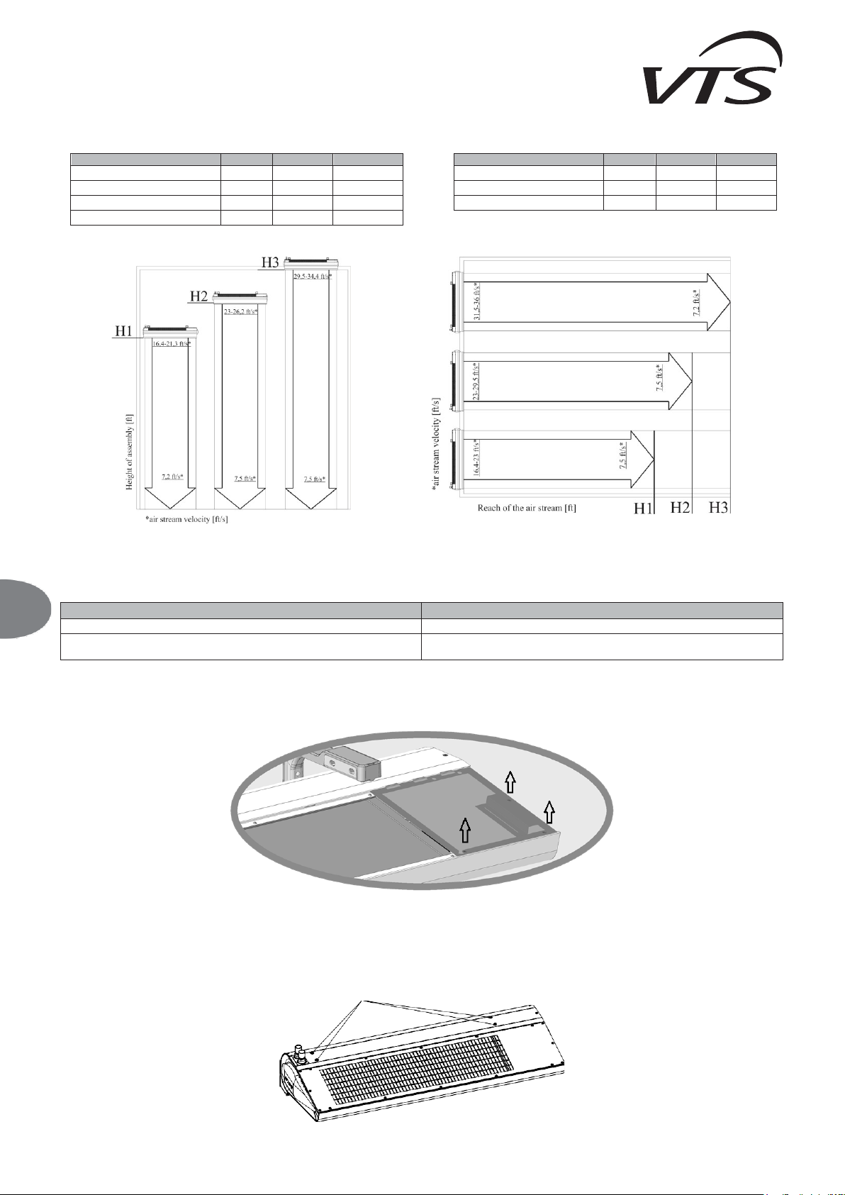
The range of the air jet - installation height
- Horizontal installation - Vertical installation
CAUTION! Air curtains with electric heat (models E100, E150 and E200) are not intended for vertical installation.
IMPORTANT! The heating output should be adjusted to the temperature inside the room, as well as the strength and direction of the wind outside. The primary criterion for the regulation of the
heating power is the temperature inside the room, near the door. Should a room thermostat be used, WING activates the heating mode, depending on the temperature settings.
IMPORTANT! Please consider additional factors that affect device operation.
Factors that have a negative effect on curtain operation
Factors that have a positive effect on curtain operation
doors or windows that are constantly open in the room, thus creating a draft
presence of awning, roofs etc. on the outer side of the door
constant and open access to staircases, available through the room, the chimney draft
effect
use of revolving doors
3.1. ASSEMBLY/ DISASSEMBLY OF JUNCTION BOX COVER
To access the terminal block remove the screws from the junction box cover and tilt it.
3.2. INSTALLATION OF DEVICE
For directly installation use the threaded sleeves (5/16”) in the top of the device.
5/16”
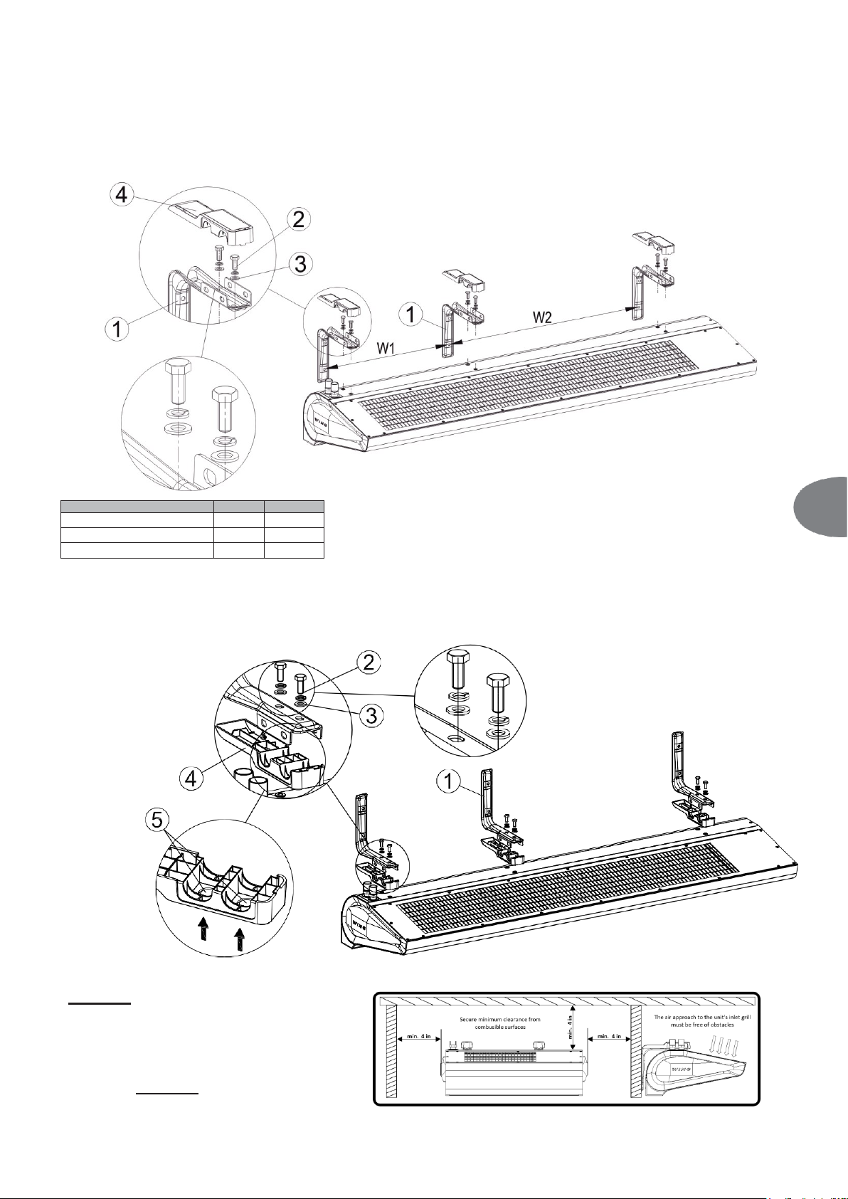
IMPORTANT! The minimum distance between the unit and the ceiling should be 4 in.
fan speed
III
II
I
height of installation [ft]
H3
H2
H1
WING W100, W150, W200
12
9-1/2
7-1/2
WING E100, E150, E200
12
9-1/2
7-1/2
WING C100, C150, C200
13
9-1/2
7-1/2
fan speed
III
II
I
width of the door [ft]
H3
H2
H1
WING W100, W150, W200
12
9-1/2
7-1/2
WING C100, C150, C200
13
9-1/2
7-1/2
EN
WING W100-200
WING E100-200
WING C100-200
6
3.2.1. HORIZONTAL INSTALLATION BY MEANS OF BRACKETS.
It is possible to install the WING do the wall horizontally in two options:
OPTION I: installation brackets with their arms faced upwards. In this option you should first screw the installation brackets to the wall (1) with intervals W1 for a 42in curtain (there are 2 installation
handles) and W1, W2 for 62in and 82in curtain (there are 3 installation handles) so that the handles' arms are levelled. Then lift the curtain and assembly with using screws (2) 1/4-UNC x 3/4 and plain
washers (3). Tighten the screws (2) and close the handle's covers (4).
W1 [in]
W2 [in]
WING W, E, C100
30 - WING W, E, C150
20
30
WING W, E, C200
36
35
OPTION II: Installation brackets with their arms faced downwards.
Installation consists in screwing brackets to the curtain (1). To mount the brackets to the curtain, with the housing upside down, punch holes (5) from the outside in the shields (4) using a hammer and a
screw. Click the shields on the brackets (1). Mount the brackets on the curtain using 1/4-UNC x 3/4 screws (2) and washers (3). This installation option allows for mounting brackets to the curtain first,
and then screwing the entire housing to the wall.
Caution!
For any of above listed installation
method, the minimum distance between
the unit and the ceiling/side walls -
minimum 4 inches.
EN

7
3.2.2. VERTICAL INSTALLATION USING INSTALLATION BRACKETS.
It is possible to install WING to a wall vertically on both sides of the gate (with the motor on the bottom or on the top).
For this option it is not important if you screw the handles down to the unit first and then screw the whole down to the wall or first attach the handles to the wall and then screw the curtain down to the
handles.
To install the curtain vertically, use 1/4-UNC x 2 3/4 (outside the scope of VTS delivery) screws. Screw 2 or 3 brackets using the screws, passing through flat washers (3), to the threaded sleeves mounted
in the upper part of the housing.
IMPORTANT: For vertical installation, keep minimum distance of 4 inches between the floor and the lower end of the curtain. This is to secure free access to the water coil air vent.
E
IMPORTANT! The device is intended for the operation in dry rooms, exclusively. Thus, pay particular attention to the condensation of wat er vapor on engine elements, since it is not fitted
for operating in humid environment.
IMPORTANT! The WING air curtains are not intended for the installation:
● Outdoor.
● In humid rooms;
● In rooms categorized as explosive environments.
● In rooms with very high levels of dustiness;
● In rooms with aggressive atmosphere (due to the presence of copper and aluminum structural elements in the heat exchanger and electric heaters).
IMPORTANT! The WING EH air curtains are not intended for the installation on suspended ceilings.
3.3. INSTALLATION GUIDELINES
CONNECTION OF THE HEATING MEDIUM
When connecting the air curtain to the heating water pipeline, secure the coil headers from excessive torque using set of two keys. The weight of installed pipelines should not impose a load on
the heater’s headers.
IMPORTANT! Pay particular attention to the leak-tightness of connections, when filing the hydraulic system. Make sure that the water flowing from a leaky connection does not leak to the
electric engine (at the vertical installation)
IMPORTANT! It is recommended to use filters in the hydraulic system. It is recommended to clean/rinse the system, draining a few liters of water, prior to the connecting of hydraulic conduits
(the supply conduits, in particular).
EXAMPLE OF HYDRAULIC SYSTEM
1. WING 100-200
2. VALVE WITH ACTUATOR
3. VENT VALVE
4. SHUT-OFF VALVE
5. FILTER
6. CIRCULATING PUMP
7. BOILER
1
VENTING OF DEVICE/DRAINING OF HEATING MEDIUM
To perform horizontal and vertical installation, the exchanger on the right-hand side of the door vents automatically. In the case of horizontal installation with the stub pipes facing downwards, to
vent the exchanger, remove the side cover. Unscrew the screws (1) around the cover and remove the cover. A valve with a hose is situated below the cover.
RETURN
SUPPLY
SUPPLY
RETURN
min.
4 in
EN

WING W100-200
WING E100-200
WING C100-200
8
VENTING OF DEVICE/DRAINING OF HEATING MEDIUM
Venting of the curtain water coil followed by loosening the union connection on the outlet connection. In case of the vertical installation with the coils connection on the bottom side, the access
to the vent valve is by removing the side cover. To do it one should remove the screws (1) around the cover and lift the cover. There is a valve (2) with a hose.
VENT/DRAIN MARKING
2 3
3
2
1
IMPORTANT! While venting the exchanger you should pay special attention to securing the device against accidental penetration of water into electrical elements.
IMPORTANT! Remember to vent the heater, if it has been activated after a prior draining of the heating medium.
IMPORTANT! Pay particular attention to the leak-tightness of connections, when filing the hydraulic system. Make sure that the water flowing from a leaky connection does not leak to the
electric engine (at the vertical instaallation).
CONNECTING OF POWER SUPPLY
IMPORTANT! The system must be equipped with protective equipment that guarantees the disconnecting of the device on all poles of the power source.
Connection to the electric system must be performed by a duly authorized and qualified person. Wire grommets are located on the back side of the curtain, a per drawing below.
• Central gland [1]
o Power supply input
• Left gland [2]
o Heating stage control signals input - only Wing air curtains with electric heat (E type)
• Right gland [3]
o Fan revolutions control signal input
CAUTION
For all connections (Power supply input, Heating stage control input, Fan revolutions
control signal input):
Minimum cables rating: UL/CSA 600 Volts.
CABLES CROSSING BETWEEN THE GLANDS AND TERMINAL BLOCK
To ensure proper separation between high and low voltage cables, follow below wiring instruction:
Power supply cable (high voltage)
• Cross the cables through the central gland (No. 1 on the drawing above).
• Cross the cable through the central mounting point and tight the strain relief.
• Gently pull the cable from outside to make it straight between the gland and mounting point. Then tighten the
gland.
• Connect the wires to the relevant high-voltage terminals.
Heating stages control H1 & H2 (High voltage)
• Cross the cables through the gland no. 2 on the drawing above.
• Cross the cable through its mounting point (see diagram on the right) and tight the strain relief.
• Gently pull the cable from outside to make it straight between the gland and mounting point. Then tight the
gland.
• Connect the wires to the relevant high-voltage terminals.
Low voltage cable (0-10 volts fan revolutions control (low voltage)
• Cross the cable between the small gland no 3 on the drawing above.
• Mount the cable to the top mounting arm of the motor using cable tie (supplied with the curtain kit) – auxiliary
mounting point no 1.
• Cross the cable through its mounting point (see diagram on the right) tighten the strain relief.
• Cross the cable through auxiliary mounting points no 2 and 3.
• Connect the wires to the relevant low-voltage terminals.
• Gently pull the cable from outside to make it straight between the gland and mounting point. Then tighten the
gland.
*Heating stages high-voltage control signals concern only Wing air curtains with electric heat.
Cables marked as below:
Power supply cable
Electric heating stages control signal cable
0-10 volts fan revolutions control cable
EN
WORKING POSITION
A
horizontal (downward air feed)
drain
automatic venting
B
vertical (air feed from left to right)
drain
automatic venting
C
vertical (air feed from right to left
venting
drain
Heating stages cable
mounting point
Power supply cable
mounting point
0-10 volts cable
auxiliary mounting
point 2
0-10 volts cable
auxiliary mounting
point 1
Power supply cable
gland
Heating stages
cable gland
0-10 volts
cable gland
0-10 volts cable
auxiliary mounting
point 3

Recommended safety devices and wires
Device
WING E100-200
E100 E150 E200
Supply voltage 1~240V
MCB
35A
MCA
33.5A
FLA
27.1A
Power wire cross-section
3 x 10 AWG
Cable Nominal Voltage UL/CSA 600 V
Supply voltage 3~240V
MCB
25A
45A
55A
MCA
20.5A
38.8A
49.8A
FLA
16.7A
32A
40.6A
Power wire cross-section
5 x 12 AWG
5 x 10 AWG
5 x 8 AWG
Cable Nominal Voltage UL/CSA 600 V
Supply voltage 3~480V
MCB
15A
25A
30A
MCA
11A
20.2A
26.7A
FLA
9.1A
17.2A
22.1A
Power wire cross-section
5 x 14 AWG
5 x 12 AWG
5 x 12 AWG
Cable Nominal Voltage UL/CSA 600 V
IMPORTANT! The specification of cables and protections refers to unbounded arrangement of. One should always abide by the local laws and recommendations concerning device connection.
WING is equipped with a terminal strip adjusted to an appropriate thickness of wires.
Air curtain model
Terminals view
Terminals description and function
WING E100 240/1/60 EC
L1 – Power supply phase
L2 – Power supply phase
– Ground
1L1 – N/C
L2 – N/C
2 – first heating stage controlled by applying
240VAC
3 – second heating stage controlled by applying 240VAC
Ai – 0-10VDC analog input for fan speed regulation
G – Reference ground for 0-10VDC speed regulation
– connected internally
1L1 – connected internally
L2 – connected internally
WING E100 240/3/60 EC
L1 – Power supply phase
L2 – Power supply phase
L3 – Power supply phase
– Ground
1L1 – N/C
L2 – N/C
2 – first heating stage controlled by applying
240VAC
3 – second heating stage controlled by applying 240VAC
Ai – 0-10VDC analog input for fan speed regulation
G – Reference ground for 0-10VDC speed regulation
– connected internally
L1 – connected internally
L2 – connected internally
WING E100 480/3/60/HLD EC
L1 – Power supply phase
L2 – Power supply phase
L3 – Power supply phase
– Ground
1L1 – N/C
L2 – N/C
2 – first heating stage controlled by applying
240VAC
3 – second heating stage controlled by applying 240VAC
Ai – 0-10VDC analog input for fan speed regulation
G – Reference ground for 0-10VDC speed regulation
– connected internally
1L1 – connected internally
2L2 – connected internally
WING E150 240/3/60 EC
WING E200 240/3/60 EC
L1 – Power supply phase
L2 – Power supply phase
L3 – Power supply phase
– Ground
1L1 – N/C
L2 – N/C
2 – first heating stage controlled by applying
240VAC
3 – second heating stage controlled by applying 240VAC
Ai – 0-10VDC analog input for fan speed regulation
G – Reference ground for 0-10VDC speed regulation
– connected internally
1L1 – connected internally
L2 – connected internally
WING E150 480/3/60/HLD EC
WING E200 480/3/60/HLD EC
L1 – Power supply phase
L2 – Power supply phase
L3 – Power supply phase
– Ground
1L1 – N/C
L2 – N/C
2 – first heating stage controlled by applying
240VAC
3 – second heating stage controlled by applying 240VAC
Ai – 0-10VDC analog input for fan speed regulation
G – Reference ground for 0-10VDC speed regulation
– connected internally
1L1 – connected internally
2L2 – connected internally
WING W100 240/1/60 EC
WING W150 240/1/60 EC
WING W200 240/1/60 EC
L1 – Power supply phase
L2 – Power supply phase
– Ground
1L1 – N/C
L2 – N/C
2 – input signal form HMI to control on/off valve
9 – valve with actuator Control
10 – valve with actuator control
Ai – 0-10VDC analog input for fan speed regulation
G – Reference ground for 0-10VDC speed regulation
– connected internally
1L1 – connected internally
L2 – connected internally
WING C100 240/1/60 EC
WING C150 240/1/60 EC
WING C200 240/1/60 EC
L1 – Power supply phase
L2 – Power supply phase
– Ground
L1 – N/C
L2 – N/C
Ai – 0-10VDC analog input for fan speed regulation
G – Reference ground for 0-10VDC speed regulation
– connected internally
1L1 – connected internally
L2 – connected internally
Device
WING W100-200 and WING C100-200
W/C100
W/C150
W/C200
Fan supply voltage 1~240V
MOP
15
15
15
MCA
1.9A
2.8A
4.4A
FLA
1.5A
2.2A
3.5A
Power wire cross-section
3 x 14 AWG
Cable Nominal Voltage UL/CSA 600 V

WING W100-200
WING E100-200
WING C100-200
10
Air curtains control
• The motor is controlled by applying voltages in the range 0-10VDC to terminals Ai and G
• The motor will not start when a voltage of 0-1VDC is applied to terminals Ai and G
• The motor speed is controlled by changing the voltage supply to the terminals Ai and G in the range 1-10VDC. The value of the given voltage in a linear manner influences the motor speed in the
range from 10-100% of its full efficiency.
• The electric heating coils should only be turned ON when the motor is running at least 45% of its full capacity. Starting electric heating coils when the motor is switched OFF can be dangerous and
can lead to damage to the device.
• Electric heating coils are divided into two independent sections controlled by applying 240VAC to terminals 2 and 3 on the terminals of electric curtains
EN
IMPORTANT!
• It is recommended to connect wires to the terminal strip with previously clamped appropriate clip ends.
• Make sure that the space around the place where the air is sucked in by the curtains, as well as around the exhaust grid, is free of any structural elements of the building, which might hamper the
flow of air (e.g. suspended ceilings, covering development, ventilating ducts etc.).

HMI-WING EC
4. ELEMENTS OF CONTROLS.
Electrical connections can be carried out only by qualified electricians, according to the binding regulations of:
● industrial safety;
● installation instructions.
● technical documentation for each individual element of automatics.
IMPORTANT! Before starting the controls installation, please read the operation and installation instruction for each of them. Instructions are included in the box for each control.
MODEL
DIAGRAM
TECHNICAL DATA
COMMENTS
HMI WING UL
HMI-WING UL
•
Device operation: touch buttons
•
Power supply: 120-240 V AC
•
Temperature measurement: 14 °F ... 210 °F ; NTC10K
•
Outputs:
- 1 analog output 0-10V (8 bit, Imax = 20 mA)
- 2 relays outputs (250 VAC, AC1 500 VA dla 230 VAC)
•
Communication: Modbus RTU
•
used for control all types of WING EC curtains
•
touch control panel
•
the main on / off switch (ON / OFF)
•
three-stage adjustable fan speed of the EC motor
•
built-in thermostat with possibility weekly programing
•
continuous mode
•
function of heating and ventilation
•
door sensor operation
•
3-levels of heating power
•
RS 485 with ModbusRTU
•
Suggested cross sections of electrical cables::
- L, N : 2x18 AWG
- H1, H2 : 2x18 AWG
- AO, GND : 2x18 AWG
- RS 485 : 2xAWG18
TWO-WAY VALVE WITH
ACTUATOR
TWO-WAY VALVE
● Terminal diameter: 3/4”
● Mode of operation: two-way ON/OFF
● Maximum differential pressure: 13psi
● Pressure class: PN 16
● Kvs flow ratio: 2.65 CFM
● Maximum temperature of heating medium: 200°F
● Parameters of working environment: from 32 to 140°F
VALVE ACTUATOR
● Power consumption: 7 VA
● Supply voltage: 230VAC +/-10%
● Closing/opening time: 4-5/9-11 s
● Position without power: closed
● Level of protection: IP54
● Parameters of working environment: from 89 to 200°F
● It is recommended to install a two-way valve on the return pipeline.
● The drawings with the elements of automatics contain only visualizations of
sample products.
● It is recommended to connect the supply, using a conductor of the min. size
0.08x0.03 in2.
● The drawings with the elements of automatics contain only visualizations of
sample products.
IMPORTANT! If required, the conductors that belong to additional elements of control automatics (thermostat, door switch, wall-mounted controller) should be installed in separate cable
channels, out-of-parallel to the supply conductors.
5. START-UP, OPERATION, MAINTENANCE
5.1. START-UP/PUTTING INTO OPERATION
● Prior to the commencing of any installation or maintenance work, disconnect power supply and secure it against unintentional reactivation.
● It is recommended to use filters in the hydraulic system. It is recommended to clean/rinse the system, draining a few liters of water, prior to the connecting of hydraulic conduits (the supply conduits,
in particular).
● It is advised to use vent valves in the highest point of the system.
● It is recommended to install shut-off valves directly after the device, should the disassembly of the device be necessary.
● All protective equipment is to be installed before the pressure increases, according to maximum the permissible pressure rating of 232 psi.
● Hydraulic connection should be free of any stresses and loads.
● Check the correctness of hydraulic connections (leak-tightness of the vent, collecting pipes, correctness of fittings installation), prior to the initial start-up of the device.
● It is recommended to check the correctness of electrical connections (of automatics, power supply), prior to the initial start-up of the device. It is advised to use an additional, external residual-
current protection.
IMPORTANT! All connections should be carried out, according to this technical documentation and the documentation delivered with automation equipment.
5.2. OPERATION AND MAINTENANCE
● It is advised to carefully analyze all the operational and installation guidelines listed in chapter 3 and 4.
● The casing of the device does not require maintenance.
● The heat exchanger should be cleaned on a regular basis from dust and fat deposit. It is especially recommended to clean the exchanger before the heating season with the use of compressed air
from the air intake side (after removing the inlet grid). You should pay special attention to the exchanger's lamellae which are very delicate.
● Should the lamellas be deformed (bent), straighten them with a special tool.
● The fan's motor does not require any exploitation service, the only service activities that may be necessary concern cleaning the air intakes from dust and fat deposit.
● Disconnect phase voltage, if the device is shut down for longer periods of time.
● The heat exchanger does not have any anti-freezing protections.
● It is recommended to provide a periodical purging of the heat exchanger, preferably using compressed air.
● Should the temperature in the room drop below 32°F, with a simultaneous drop of the heating medium temperature, there is a risk that the heat exchanger might freeze (crack).
● The level of air pollutants should meet the criteria allowable concentrations of pollutants in indoor air, for non-industrial areas, the level of dust concentration up to 1.87x10⁻⁵ lbs/ft3.
● It is forbidden to use device for the duration of the construction works except for the start-up of the system.
● The equipment must be operated in rooms used throughout the year, and in which there is no condensation (large fluctuations in temperature, especially below the dew point of the moisture
content). The device should not be exposed to direct UV rays.
● The device should be operated at the supply water temperature up to 200 °F with working fan.
EN

WING W100-200
WING E100-200
WING C100-200
12
6. SERVICING
6.1. PROCEDURE IN CASE OF MALFUNCTION
EN
It is forbidden to place, dispose of and store worn-out electric and electronic equipment, together with other waste. Dangerous compound contained in electronic
and electric equipment have a very adverse impact on plants, micro-organisms, and, most importantly, on humans, as they damage our central and peripheral
nervous system, as well as circulatory and internal system. Additionally, they cause serious allergic reactions. Worn-out equipment is to be delivered to a local
collection point for used electric equipment, which carries out a selective collection of waste.
REMEMBER!
The user of equipment intended for households, and which has been worn out, is obliged to transfer such equipment to a collecting unit that collects worn-out
electric and electronic equipment. The selective collecting and further processing of waste from households contributes to the protection of environment,
reduces the penetration of hazardous substances into the atmosphere and surface waters.
6.2. COMPLAINT PROCEDURE
In order to report a problem with the device or elements of automation, please fill in and send the appropriate form (p.74), using one of the three available ways:
1. E-mail:
america@vtsgroup.com
2. Fax: +1 470-809-6815
3. Website: https://vtsgroup.com/us/service-vts
Our service department will contact you immediately.
In the case of damage in transport, send a complaint notification, including the delivery documentation (bill of lading, inventory issue) and photographs showing the defects.
Should you have any questions, please contact us, using this telephone number: +1 470-809-6811
IMPORTANT! The complaint procedure shall be initiated when the Service Department has received a correctly filled complaint notification, a copy of the purchase invoice and the Warranty
Card, filled by the company that carried out the installation.
7. INDUSTRIAL SAFETY INSTRUCTION
Special instructions concerning safety
IMPORTANT!
● Prior to the commencing of any work related to the device, it is required to disconnect the system, secure it properly and wait, until the fan stops revolving.
● Use stable working platforms and hoists.
● Depending on the temperature of the heating medium, pipes, elements of casing and surfaces of the heat exchanger can be very hot, even after the fan has stopped revolving.
● Sharp edges may be present! Wear gloves, protective shoes and clothing, when transporting the device.
● Strictly observe safety guidelines and industrial safety regulations.
● Loads can be placed only in the previously selected areas on the transporting unit. Protect the edges of the device, when lifting it, using a set of machines. Remember to distribute weight evenly.
● The equipment must be protected against moisture and dirt, and kept in rooms protected against the impact of weather conditions.
● Utilization of waste: make sure that operating and auxiliary materials, including packaging material and spare parts, are disposed of in a safe, environment friendly manner, according to the binding,
local statutory regulations.
WING W100-200/EHN
Symptoms
What to check
Description
Leakage in the WING
W100-200 heat
exchanger
● Fitting of the heat exchanger terminals, using two keys acting in two opposite
directions (apply the keys on each terminal), which protects against the possibility
of internal breaking of the collecting pipes.
● Relation between the leaking and a potential mechanical damage to the
exchanger.
● Leaking of vent valve elements or drain plug.
● Parameters of the heating medium (pressure and temperature) should not
exceed the permissible values.
● Correctness of the draining of the exchanger.
● type of agent (it cannot be any aggressive substance Al or Cu active),
● Circumstances in which leaking occurred (e.g. during the trial/initial start-up of
the system; after having drained the heating medium, followed by the filling of
the system) and the external ambient temperature at the moment of the defect
taking place (freezing hazard to the exchanger).
● Potentially aggressive atmosphere (air) in the place of work (e.g. high
concentration of ammonia in the sewage-treatment plant).
● Pay particular attention to the possibility of the freezing of the heat
exchanger in the winter. 99% of leaks occur during start-up/pressure
checks. The rectifying of the defect consists in the pulling back of the
vent/drain valve.
The fan of the device
works too loudly WING
W100-200, EHN
● Installation of the device, according to the guidelines in the Operation and
Maintenance Documentation (among others, the distance from the ceiling).
● Minimum distance: 4 in from the ceiling
● Correctness of the horizontal alignment of the device.
● Correctness of electrical connections and qualifications of
● Parameters of the supply current (among others: voltage, frequency).
● Incorrect covering of the curtain in the suspended ceiling.
● Noise in lower speeds (damaged winding).
● Noise present only in the higher speeds – blocking of the air outlet.
● Type of other equipment working in the facility (e.g. exhaust fans) – increasing
noise may be a result of several pieces of equipment working simultaneously.
● Louder operation of WING devices may be a result of inappropriate place
of installation: e.g. choking the fan or the acoustic specifics of a room.
The fan in the device
is not operational
WING W100-200
● Correctness and quality of electrical connections and qualifications of the fitter.
● Parameters of the supply current (among others: voltage, frequency) on the
terminal block of the fan’s engine.
● Operational correctness of other pieces of equipment present in the facility.
● Correct fitting of the conduits on the engine side – information available from VTS
Service Department.
● Voltage on the PE conductor (if present, it may indicate a breakdown).
● The electrical connection of the device must be carried out, according to
the diagrams found in the Operation and Maintenance Documentation.
Damaged casing of the
device
WING W100-200
● Circumstances in which the defect occurred: remarks on the bill of lading,
inventory issue, condition of cardboard).
● Should the casing be defective, it is required to present photos of the
cardboard and device, as well as photos that confirm the compliance
between the serial number on the device and cardboard. If the damage
was done in transport, it is necessary to prepare a proper statement by the
driver/forwarder that delivered the goods.
Actuator does not open
the valve
● Correctness of electrical connections and qualifications of the fitter.
● Operational correctness of the thermostat (the characteristic “ticking” when
switching the device).
● Parameters of the supply current (among others: voltage).
● The most important step is to check whether the actuator has reacted to
the electrical impulse within 11 s. When actuator damage is claimed, a
complaint must be submitted for the damaged element, and the actuator
must be uninstalled from the valve to open the valve mechanically
(permanently).
EN

13
8. TECHNICAL SPECIFICATION
8.1. WATER AIR CURTAIN – WING W100-200
T
z –
temperature of water at the inlet to the device
Tp – temperature of water at the outlet from the device
T
p1
– temperature of air at the inlet to the device
T
p2
– temperature of air at the outlet from the device
P
g –
heating output of the device
Qw – water flow
Δp – pressure drop in the heat exchanger
EN
Parameters
WING W150
Tz/Tp [°F]
164/158
176/140
158/122
140/104
T
p1
[°F]
41
50
59
68
41
50
59
68
41
50
59
68
41
50
59
68
III/1824[CFM]/61dB(A)*
P
g
[MBH]
108
100
91
83
91
83
75
67
75
66
59
50
58
49
41
32
T
p2
[°F]
93
99
104
110
85
90
96
102
77
82
88
93
69
74
79
84
Qw [CFM]
0.82
0.76
0.70
0.64
0.70
0.64
0.59
0.53
0.59
0.53
0.47
0.41
0.41
0.35
0.29
0.23
Δp [psi]
0.304
0.261
0.232
0.188
0.232
0.203
0.174
0.130
0.174
0.145
0.116
0.087
0.116
0.087
0.058
0.043
II/1206[CFM]/48dB(A)*
P
g
[MBH]
90
83
76
70
76
70
63
56
63
56
49
42
48
41
34
26
T
p2
[°F]
98
104
109
114
89
95
100
105
81
86
91
96
71
76
81
85
Q
[CFM]
0.70
0.64
0.59
0.53
0.59
0.53
0.47
0.41
0.47
0.41
0.35
0.29
0.35
0.29
0.23
0.17
Δp [psi]
0.217
0.188
0.174
0.145
0.174
0.145
0.116
0.101
0.130
0.101
0.087
0.058
0.087
0.058
0.043
0.029
I/835[CFM]/43dB(A)*
P
g
[MBH]
73
68
62
57
62
57
51
46
51
45
40
34
39
33
27
16
T
[°F]
104
110
115
120
95
100
105
110
85
90
95
99
75
79
83
83 Q[CFM]
0.60
0.53
0.47
0.41
0.47
0.41
0.41
0.35
0.41
0.35
0.29
0.23
0.29
0.23
0.23
0.12
Δp [psi]
0.159
0.130
0.116
0.101
0.116
0.101
0.087
0.072
0.087
0.072
0.058
0.043
0.058
0.043
0.029
0.014
Parameters
WING W200
T/T[°F]
164/158
176/140
158/122
140/104
T
p1
[°F]
41
50
59
68
41
50
59
68
41
50
59
68
41
50
59
68
III/2589[CFM]/62dB(A)*
P
[MBH]
160
145
134
122
134
122
111
100
111
99
88
76
87
76
64
52 T[°F]
94
100
106
111
86
92
98
103
78
84
90
95
70
76
81
86
Qw [CFM]
1.17
1.12
1.00
0.94
1.00
0.94
0.82
0.76
0.82
0.76
0.64
0.59
0.64
0.59
0.47
0.41
Δp [psi]
0.812
0.710
0.609
0.522
0.623
0.536
0.449
0.377
0.464
0.377
0.304
0.246
0.319
0.246
0.188
0.130
II/1854[CFM]/48dB(A)*
P
[MBH]
139
129
118
108
119
108
98
88
98
88
78
68
77
67
57
46
T
p2
[°F]
97
103
109
114
89
95
100
106
81
86
92
97
72
78
83
88
Qw [CFM]
1.06
1.00
0.88
0.82
0.88
0.82
0.76
0.64
0.76
0.64
0.59
0.53
0.59
0.53
0.41
0.35
Δp [psi]
0.652
0.565
0.493
0.420
0.507
0.435
0.362
0.304
0.377
0.304
0.246
0.203
0.261
0.203
0.145
0.101
I/1206[CFM]/45dB(A)*
P
g
[MBH]
116
107
98
90
99
90
82
73
82
73
65
56
64
56
47
38
T
p2
[°F]
103
109
114
119
94
100
105
110
85
90
95
100
76
81
85
90
Qw [CFM]
0.88
0.82
0.76
0.70
0.76
0.70
0.64
0.59
0.64
0.59
0.47
0.41
0.47
0.41
0.35
0.29
Δp [psi]
0.464
0.406
0.348
0.304
0.362
0.319
0.261
0.217
0.275
0.232
0.174
0.145
0.188
0.145
0.101
0.072
Parameters
WING W100
Tz/Tp [°F]
194/158
176/140
158/122
140/104
T
p1
[°F]
41
50
59
68
41
50
59
68
41
50
59
68
41
50
59
68
III/1088[CFM]/59dB(A)*
P
[MBH]
60
55
50
46
50
45
40
35
39
34
29
23
27
17
14
12
T
p2
[°F]
89
95
101
107
81
87
92
98
73
78
83
88
63
64
71
78
Qw [CFM]
0.47
0.41
0.41
0.35
0.41
0.35
0.29
0.29
0.29
0.29
0.24
0.18
0.24
0.12
0.12
0.12
Δp [psi]
0.073
0.058 0.058 0.044 0.058 0.044 0.029 0.029 0.029 0.029 0.015 0.015 0.015
0.015 0.006
0.00
4
II/794[CFM]/48dB(A)*
P
[MBH]
51
47
43
39
42
38
34
30
33
29
24
16
18
15
13
11 T[°F]
94
100
105
110
85
90
96
101
76
81
85
85
60
66
73
80
Qw [CFM]
0.41
0.35
0.35
0.29
0.35
0.29
0.24
0.53
0.24
0.24
0.18
0.12
0.12
0.12
0.12
0.06
Δp [psi]
0.058
0.044
0.044
0.029
0.044
0.029
0.029
0.015
0.029
0.015
0.015
0.015
0.015
0.015
0.006
0.004
I/518[CFM]/44dB(A)*
P
[MBH]
40
37
33
30
33
30
27
23
26
22
15
13
15
13
11
9
T
p2
[°F]
101
106
111
116
91
96
100
104
79
83
83
89
64
70
76
83
Qw [CFM]
0.29
0.29
0.24
0.24
0.24
0.24
0.24
0.18
0.18
0.18
0.12
0.12
0.12
0.12
0.12
0.06
Δp [psi]
0.029
0.029
0.029
0.015
0.029
0.015
0.015
0.015
0.015
0.015
0.015
0.000
0.015
0.006
0.004
0.003

WING W100-200
WING E100-200
WING C100-200
14
8.2. ELECTRIC AIR CURTAIN – WING E100-200
T
p1
– temperature of air at the inlet to the device
T
p2
– temperature of air at the outlet from the device
P
g
– heating output of the device
Parameters
WING E100
WING E150
WING E200
T
[°F]
41
50
59
68
41
50
59
68
41
50
59
68
III/1088[CFM]/59dB(A)*
III/1854[CFM]/61dB(A)*
III/2648[CFM]/62dB(A)*
P
g
[kW]
2/4/6
2/4/6
2/4/6
2/4/6
4/8/12
4/8/12
4/8/12
4/8/12
6/9/15
6/9/15
6/9/15
6/9/15
T
[°F]
46/51/59
55/60/68
64/69/77
73/78/86
48/53/59
57/62/68
66/71/77
75/80/86
48/50/57
57/59/66
66/68/75
75/77/84
II/824[CFM]/48dB(A)*
II/1206[CFM]/48dB(A)*
II/1883[CFM]/48dB(A)*
P
g
[kW]
2/4/6
2/4/6
2/4/6
2/4/6
4/8/12
4/8/12
4/8/12
4/8/12
6/9/15
6/9/15
6/9/15
6/9/15
T
p2
[°F]
48/53/60
57/62/69
66/71/78
75/80/87
50/57/66
59/66/75
68/75/84
77/84/93
50/53/60
59/62/69
68/71/78
77/80/87
I/541[CFM]/44dB(A)*
I/853[CFM]/43dB(A)*
I/1265[CFM]/45dB(A)*
P
g
[kW]
2/4/6
2/4/6
2/4/6
2/4/6
4/8/12
4/8/12
4/8/12
4/8/12
6/9/15
6/9/15
6/9/15
6/9/15
T
p2
[°F]
51/60/69
60/69/78
69/78/87
78/87/96
55/66/78
64/75/87
73/84/96
82/93/105
53/59/69
62/68/78
71/77/87
80/86/96
8.3. WING C100-200 – COLD AIR CURTAIN
Parameters
WING C100
WING C150
WING C200
Fan speed
III
II I III
II I III
II I Qp [CFM]
1147
882
618
1883
1324
882
2707
2001
1377
noise level [dB(A)]*
62
49
45
63
49
43
63
49
45
* The noise level has been measured within a 10 ft distance from the device; reference conditions: semi-open space – wall-mounted device.
Parameters
WING W100-200
WING E100-200
WING C100-200
unit of
measure
W100
W150
W200
E100
E150
E200
C100
C150
C200
Maximum width of a single door for one
device
in
39
59
79
39
59
79
39
59
79
Maximum height of door
ft
12
13
Heating output range
MBH
13 –
58
34 – 109
58 –
160
7/20 or 14/20
13/41
or
27/4
1
20/51 or
30/51
-
Maximum flow rate
CFM
1089
1824
2589
1088
1854
2648
1147
1883
2707
Maximum temperature of heating
medium
°F
200 - -
Maximum working pressure
psi
232 - -
Water volume
in³
97
158
219
-
-
Diameter of stub pipe connectors
"
3/4 - -
Supply voltage
V/ph/Hz
~240/1/(50/6
0)
~240/1/(50/60)
or
~240/3/(50/60)
or
~480/3/(50/60)
~240/3/(50/60) or
~480/3/(50/60)
~240/1/(50/6
0)
Power of the electric heater
kW - 2 and 4
4 and 8
6 and 9
-
Rated current of the electric heater
A
-
9 or
5/10/15 or
3/5/8
10/20/30 or
5/10/15
15/22/37 or
8/11/19
- -
-
EC Engine power
HP
0,27
0,4
0,64
0,27
0,4
0,64
0,27
0,4
0,64
EC engine rated current
A
1.5
2.2
3.5
1.5
2.2
3.5
1.5
2.2
3.5
Weight
lbs 47 64 83 49 67 86 42 56 72
IP
-
20
EN

15
9. ELECTRICAL DIAGRAMS
9.1. Electrical diagram of WING W100-200-EC – 1~240V

WING W100-200
WING E100-200
WING C100-200
16
9.2. Electrical diagram of WING C100-200-EC – 1~240V

17
9.3. Electrical diagram of WING E100-EC 1~240V

WING W100-200
WING E100-200
WING C100-200
18
9.4. Electrical diagram of WING E100-EC -3~240V
19
9.5. Electrical diagram of WING E100-EC- 3~480V

WING W100-200
WING E100-200
WING C100-200
20
9.6. Electrical diagram of WING E150-200-EC- 3~240V

21
9.7. Electrical diagram of WING E150-200-EC- 3~480V
WING W100-200
WING E100-200
WING C100-200
22
Complaint Form
VTS America Inc.
3535 Gravel Springs Rd
Ext #203, Buford, GA
30519
PH: 470-809-6811, FAX:
470-809-6815
The company submitting the notification:
The company that installed the equipment:
Date of notification:
Type of device:
Factory number*:
Date of purchase:
Date of installation:
Place of installation:
Detailed description of defect:
Contact person:
Name and surname:
Telephone:
E-mail:
* This field must be filled, if the complaint notification refers to the following equipment: VOLCANO VR1, VR2, VR3 and VRMini unit, and WING air curtains.
23
Warranty card
1. Stamp of the company to carry out installation
VTS America Inc.
3535 Gravel Springs Rd Ext #203, Buford, GA 30519
PH: 470-809-6811, FAX: 470-809-6815
2. Factory number of device
3. Place of installation
4. Date of installation
5. Address, street
6. Apartment number
7. City
8. Postal code
Based on these Warranty Terms and Conditions, the company from the VTS Group (hereinafter: VTS) specified in the warranty card hereby guarantees to the owner
(hereinafter: Customer) that the Volcano VR, WING W100 - 200, WING E100 – 200, WING C100 - 200 devices (hereinafter: devices) sold by VTS will work without
malfunctions.
another place, after they are sent for repair.
Service Technicians and the costs of transporting spare parts. The current list of VTS Licensed Service Centres, hereinafter service centres, is available on
www.vtsgroup.com and in VTS business offices.
item.
consent of VTS.
the device, the Operation & Maintenance Manual or by individuals without proper qualifications.
Maintenance Manual or by individuals without proper qualifications.
or whose technical inspections or maintenance activities were conduc ted by individuals without proper qualifications.
Customer other than the devices.
another country than the country of purchase, VTS is under no obligation to provide service under the warranty.
sending the electronic application specified above.
delivered to the place of repair specified by VTS. The device serial number must be consistent with the number on the original packaging and in the Warranty Card.
line with the technical service price list available on www.vtsgroup.com
necessary, to remove and re-install the devices,
the complaint,
making sure that the service performance site meets the requirements defined in legal regulations.
of the warranty service, the Customer has the right to complain to VTS. Provisions of § 4 hereof shall apply to such a complaint as appropriate.
Terms and Conditions shall prevail. In such an event, any contradictory provisions of the Proposal and the Purchase Order shall not apply.
and Conditions shall prevail.
 Loading...