

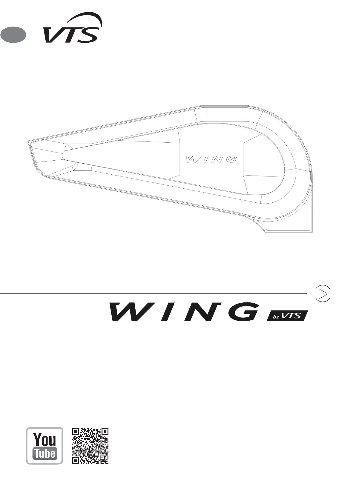
VTS WING W100-200, WING E100-200, WING C100-200 User Manual
Technical documentation
Check us on
WG.US-Rev.2.8 (09.2020)
WING W100-200
WING E100-200
WING C100-200
EN

WING W100-200
WING E100-200
WING C100-200
1. Table of content
1. INTRODUCTION ...................................................................................................................... 3
1.1. PRECAUTIONS, REQUIREMENTS, RECOMMENDATIONS ........................................ 3
1.2. TRANSPORT ................................................................................................................. 3
1.3. INITIAL STEPS TAKEN BEFORE THE INSTALLATION ................................................. 3
2. STRUCTURE, INTENDED USE, PRINCIPLE OF OPERATION ............................................ 3
2.1. INTENDED USE ............................................................................................................ 3
2.2. PRINCIPLE OF OPERATION......................................................................................... 3
2.3. STRUCTURE (WING 100-200) ...................................................................................... 4
2.4. OVERALL DIMENSIONS (WING E, W, C 100-200) ........................................................ 4
3. MOUNTING .......................................................................................................................... 4
3.1. ASSEMBLY/ DISASSEMBLY OF JUNCTION BOX COVER .......................................... 5
3.2. INSTALLATION OF DEVICE ......................................................................................... 5
3.2.1. HORIZONTAL INSTALLATION BY MEANS OF HOLDERS. ................................... 6
3.2.2. VERTICAL ASSEMBLY USING INSTALATION HOLDERS. .................................... 7
3.3. ASSEMBLY AND INSTALLATION GUIDELINES ........................................................... 7
4. ELEMENTS OF CONTTROLS. ........................................................................................... 11
5. START-UP, OPERATION, MAINTENANCE ........................................................................ 11
5.1. START-UP/PUTTING INTO OPERATION ................................................................... 11
5.2. OPERATION AND MAINTENANCE .............................................................................. 11
6. SERVICING ........................................................................................................................ 12
6.1. PROCEDURE IN CASE OF MALFUNCTION ............................................................... 12
6.2. COMPLAINT PROCEDURE ......................................................................................... 12
7. INDUSTRIAL SAFETY INSTRUCTION ............................................................................... 12
8. TECHNICAL SPECIFICATION ............................................................................................. 13
8.1. WATER AIR CURTAIN – WING W100-200 .................................................................. 13
8.2. ELECTRIC AIR CURTAIN – WING E100-200 ............................................................... 14
8.3. WING C100-200 – COLD AIR CURTAIN ...................................................................... 14
9. ELECTRICAL DIAGRAMS .................................................................................................. 15
9.1. Electrical diagram of WING W100-200-EC – 1~240V ...................................................... 15
3
1. INTRODUCTION
1.1. PRECAUTIONS, REQUIREMENTS, RECOMMENDATIONS
Detailed analysis of this documentation, as well as assembly and use of equipment, according to the descriptions contained th erein, and following all safety requirements, is the basis for the
correct and safe operation of the device. Any other use that contradicts this instruction may cause accidents with serious consequences. Unauthorized personnel should have limited access
to the device, while the personnel should be properly trained. The term operational personnel ref ers to people, who, as the result of completed training, own experience and knowledge of
important standards, documentation and provisions, concerning safety and working conditions, have been authorized to carry out necessary work and are able to recognize potential hazards
and avoid them. This technical documentation must be delivered together with the device. The documentation contains information concerning all possible configurations of air curtains.
Examples of air curtain assembly and installation, as well as activation, use, repair and maintenance. Provided that the device is operated according to the intended use, this documentation
contains a sufficient number of ins tructions, required by the qualified personnel. The documentation should be placed n ear the device and be readily available to the service team. The
manufacturer reserves the right to introduce changes to the instruction, as well as changes to the device that affect its operation, without prior notice. VTS shall bear no responsibility for ongoing maintenance, inspections, programming of equipment and damage, caused by standstills of equipment related to the waitin g for warranty services, all and any damage related to the
Client’s property, other than the device in question, as well as malfunctions that result from incorrect installation or improper use of the device.
WING air curtains are intended for indoor installation only.
DO NOT COVER
WARNING: To avoid overheating - do not cover the device!
1.2. TRANSPORT
Prior to the installing and taking the device out of the cardboard box, it is required to check whether the cardboard box has not been damaged in any way and/or the adhesive tape (in stalled
at the company) has not been broken off or cut. It is recommended to check whether the device’s casing has not been damaged in transport. Should any of the above situation occur, please
contact us through telephone or e-mail: Tel. +1 470-809-6811, email: america@vtsgroup.com, fax: +1 470-809-6815.
The device should be transported by two people. Use appropriate tools, when transporting the device, so as to avoid the damaging of goods and potential hazard to health.
1.3. INITIAL STEPS TAKEN BEFORE THE INSTALLATION
Record the serial number of the device on the warranty card, prior to the commencement of the installation process. It is required to properly fill-in the warranty card, once the installation is
complete. Prior to the commencing of any installation or maintenance work, it is required to disconnect power supply and protect it against unintentional activation.
Installation and start-up should be performed by qualified personnel, according to the guidelines provided in this manual. The order of
installation steps are as follows:
• Mount the device in its intended operation place
• Perform the hydraulic connection, check connections for tightness and vent the system
• Perform the electrical connection
• Make sure the device is correctly connected (according to the diagram)
• In the case of an electrical curtain, vacuum the heaters to avoid the unpleasant smell of burning dust
• Turn the power on and start the device.
2. STRUCTURE, INTENDED USE, PRINCIPLE OF OPERATION
2.1. INTENDED USE
For the convenience of users as well as different types of installations in commercial and industrial facilities we have designed an air curtain in three different options and three sizes:
● a WING W100 240/1/60 curtain 42in wide with a water heater (13.6-58MBH, 1089 CFM)
● a WING E100 (models: WING E100 240/1/60, WING E100 240/3/60, WING E100 480/3/60) curtain 42in wide with electric heaters (6.8/13.6/20.5 MBH, 1089 CFM)
● a WING C100 240/1/60 curtain 42in wide (1107 CFM)
● a WING W150 240/1/60 curtain 62in wide with a water heater (34.1- 109 MBH, 1825 CFM)
● a WING E150 (models: WING E10 240/3/60, WING E150 480/3/60) curtain 62in wide with electric heaters (13.6/27.3/40.9 MBH, 1854 CFM)
● a WING C150 240/1/60 curtain 62in wide (1884 CFM)
● a WING W200 240/1/60 curtain 82in wide with a water heater (58- 160 CFM, 2590 CFM)
● a WING E200 (models: WING E200 240/3/60, WING E200 480/3/60) curtain 82in wide with electric heaters (20.5/30.7/51 MBH, 2649 CFM)
● a WING C200 240/1/60 curtain 82in wide (2708 CFM)
The above sizes of curtains are available with three options of voltage supply: 1x240VAC, 3x240VAC, 3x480VAC
! Voltage supply 1x240VAC is available only for the curtains WING E100 240/1/60, all WING W and all WING C
! Caution
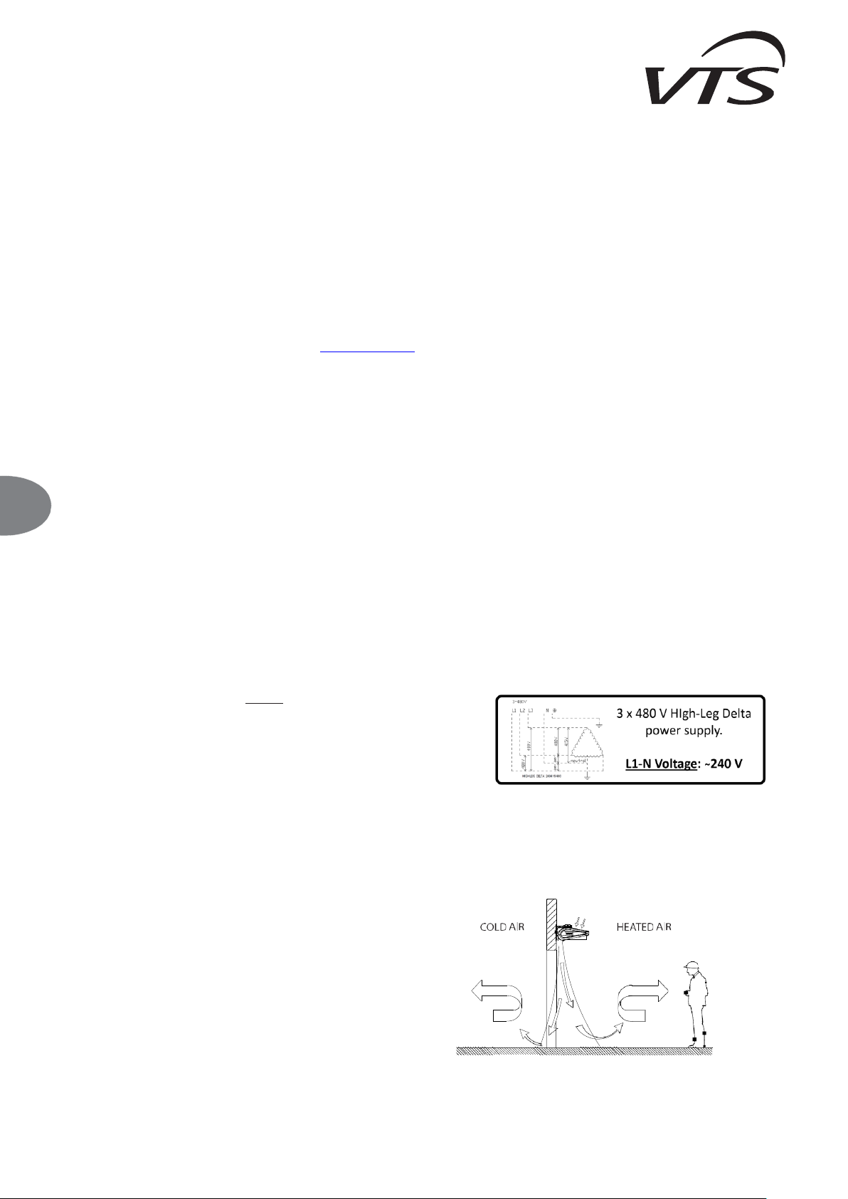
The following models of WING air curtains must be supplied using High-Leg Delta supplying
circuit:
• WING E100 480/3/60 Air Curtain
• WING E150 480/3/60 Air Curtain
• WING E200 480/3/60 Air Curtain
For these models, the L1-N voltage will must be 240 VAC.
The use of the WING air curtain enables the leaving of the room door open, regardless of weather conditions, thus providing a protective barrier. The curtain also enables a simultaneous keeping of
the required heating comfort inside the room/facility. T he modern design of the WING air curtain is a result of its wide range of application. The places in which it is possible to install the device include:
malls, office buildings, supermarkets, cinema complexes, as well as shops, store-rooms, manufacturing facilities or warehouse rooms. Please notice that the use of an air curtain not only provides a
protective barrier, but also it is an additional heat source in the room. APPLICATION: warehouse rooms, warehouses, sports facilities, supermarkets, religious buildings, hotels, clinics, pharmacies,
hospitals, office buildings, manufacturing facilities. PRIMARY ADVANTAGES: protection of climatic conditions in the room, reduction of heating/cooling costs, universal size, ability to work both in
vertical and horizontal position; simple, quick and intuitive assembly.
2.2. PRINCIPLE OF OPERATION
WING W100-200 - heating medium, for example hot heating water, returns
heat through a heat exchanger with a wide heat-exchange surface, thus
providing high heating output (13.6-160 MBH). A transverse fan (518-2590
CFM) sucks in the air in the room, and pumps it through the heat exchanger,
back into the room. The jet of warm air is directed downstream at high
velocity, thus providing an air barrier.
WING E100-200 - electric heaters (6.8-51.2 MBH) heat up, as a result of the
flowing of electric current, and return the heat to the air; the air is blown off
through the fan, which sucks in the air in the room. A jet of warm air is directed
downstream at high velocity, thus providing an air barrier.
EN
WING W100-200
WING E100-200
WING C100-200
4
2.3. STRUCTURE (WING 100-200)
WING W100-200 – WATER AIR CURTAIN
1. Heat exchanger
2. Control system
3. Transverse fan
4. Casing
5. Outlet grille
6. Assembly jigs
7. Side cover
8. Side cap
WING E100-200 – ELECTRIC AIR CURTAIN
1. Electric heaters
2. Control system
3. Transverse fan
4. Casing
5. Outlet grille
6. Assembly jigs
7. Side cover
8. Side cap
WING C100-200 – COLD AIR CURTAIN
1. Control system
2. Transverse fan
3. Casing
4. Outlet grille
5. Assembly jigs
6. Side cover
7. Side cap
1. HEAT EXCHANGER – WATER HEATER: Maximum parameters of the heating agent for the heat exchanger are: 200°F, 232 psi. The aluminum and copper construction consists of copper
pipes of the coil and aluminum lamellae. The connection manifold (¾” male thread) is situated in the upper part of the housing. An optimally selected water exchanger was adapted to work in
three positions: horizontally and vertically, with stub pipes facing upwards and downwards. Appropriate lead of hydraulic connections makes it possible for the curtain to be assembled directly by
the wall as close to the door frame as possible. The air curtain with a water heater generates power from 13.6 to 160 MBH.
ELECTRIC HEATER: each electrical curtain consists of 6 electrical heaters of 670W to 2,950W, depending on the size of the curtain. The heaters are connected into two sections of 2 and 4 kW for
a 42in curtain, 4 and 8 kW for a 62in curtain, and 6 and 9kW for an 82in curtain. The heating section is connected to form a 1x230V or 3x230V, 3x480V power supply star depend on the chosen
device. Thanks to such technical solutions and the application of a wall-mounted controller, the heater of each curtain can work in two heating programs, e.g. for a WING E100 curtain - option
1): heating program 1 - 2kW, heating program 2 - 4kW, option 2): program 1 - 4kW, program 2 - 6kW, and analogously for the remaining curtain sizes. Change of program is displayed on the
diagram and consists in a cable switch in controller HMI. The heating program is independent from the fan speed setting.
Electric heater are protected with 4 thermostats, 2 for each section: one with automatic reset and second with manual reset. The thermostat button for manual reset is available to push from
the top of the curtain via the top cover grid on the motor side.
2. CONTROL SYSTEM: it is equipped with an outlet on the connection clamp block X1 for WING W100-200 and on the X2 block for WING E100-200 for connecting an on-wall controller as well as
a valve actuator for WING W100-200. WING air curtains can be additionally equipped with a wall-mounted DX controller. The DX controller has a three-position heating switch. In the case of a
water curtain, to guarantee the proper functioning of the water valve, the heating switch must be set to position II (central) - otherwise the valve will not open.
The system of WING E100-200 is equipped with a safety device in the form of a fuse in the 115 V AC circuit.
3. HORIZONTAL FAN: the maximum temperature of operation is 200°F; the rated voltage is 240 V/60Hz. The motor protection level is IP44. The horizontal fan applied in the device with an advanced
profile of blades and impeller geometry made of plastic makes it possible to obtain air capacities up to 2648 CFM. The control of the electric motor as well as thermal protections of the winding has
been coupled with the control system which resulted in increasing safety of operation. Due to optimum power of the motor the WING curtain is energy saving and durable.
5. INSTALLATION BRACKETS: WING is characterized by simple, quick and aesthetic assembly that can be performed on a wall in both horizontal and vertical position. There are from 2
to 3 installation handles attached (as an option) to the curtain (depending on the option (length). Connections of electric wires and water channels have been especially designed not to
interfere with the general aesthetic values of the device. The name WING includes devices that are 42, 62 and 82in long that, if necessary, can be additionally joined both horizontally
and vertically to achieve different air supply options: from the left to the right and the opposite. The reach of the air stream is up to 13 ft.
2.4. OVERALL DIMENSIONS (WING E, W, C 100-200)
3. MOUNTING
IMPORTANT!
● The place of assembly should be carefully selected, taking into account the occurring of potential loads or vibrations.
● Prior to all installation or maintenance work, disconnect power supply and secure it against unintentional reactivation.
● It is recommended to use filters in the hydraulic system. It is recommended to clean/rinse the system, draining a few liters of water, prior to the connecting of hydraulic conduits (the supply
conduits, in particular).
IMPORTANT!
The air is blown out of the curtain at high velocity, along the surface of the opening, thus creating a protective barrier. Air curtains should cover the entire width of the door opening, in order to
obtain the maximum performance of the curtain.
IT IS RECOMMENDED TO TAKE INTO ACCOUNT THE FOLLOWING PARAMETERS, WHEN ASSEMBLING THE CURTAIN:
The width of the door frame should be less or equal to the width of the supplied air stream.
INCORRECT
CORRECT
EN
5
The range of the air jet - installation height
- Horizontal installation - Vertical installation
CAUTION! Air curtains with electric heat (models E100, E150 and E200) are not intended for vertical installation.
IMPORTANT! The heating output should be adjusted to the temperature inside the room, as well as the strength and direction of the wind outside. The primary criterion for the regulation of the
heating power is the temperature inside the room, near the door. Should a room thermostat be used, WING activates the heating mode, depending on the temperature settings.
IMPORTANT! Please consider additional factors that affect device operation.
Factors that have a negative effect on curtain operation
Factors that have a positive effect on curtain operation
doors or windows that are constantly open in the room, thus creating a draft
presence of awning, roofs etc. on the outer side of the door
constant and open access to staircases, available through the room, the chimney draft
effect
use of revolving doors
3.1. ASSEMBLY/ DISASSEMBLY OF JUNCTION BOX COVER
To access the terminal block remove the screws from the junction box cover and tilt it.
3.2. INSTALLATION OF DEVICE
For directly installation use the threaded sleeves (5/16”) in the top of the device.
5/16”
IMPORTANT! The minimum distance between the unit and the ceiling should be 4 in.
fan speed
III
II
I
height of installation [ft]
H3
H2
H1
WING W100, W150, W200
12
9-1/2
7-1/2
WING E100, E150, E200
12
9-1/2
7-1/2
WING C100, C150, C200
13
9-1/2
7-1/2
fan speed
III
II
I
width of the door [ft]
H3
H2
H1
WING W100, W150, W200
12
9-1/2
7-1/2
WING C100, C150, C200
13
9-1/2
7-1/2
EN
WING W100-200
WING E100-200
WING C100-200
6
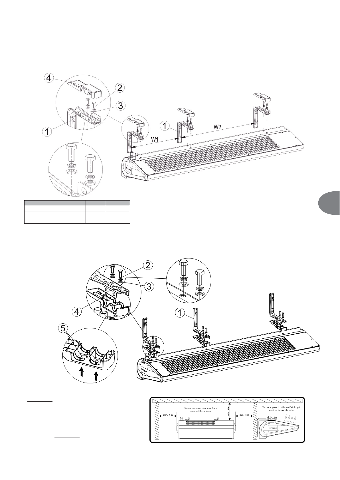
3.2.1. HORIZONTAL INSTALLATION BY MEANS OF BRACKETS.
It is possible to install the WING do the wall horizontally in two options:
OPTION I: installation brackets with their arms faced upwards. In this option you should first screw the installation brackets to the wall (1) with intervals W1 for a 42in curtain (there are 2 installation
handles) and W1, W2 for 62in and 82in curtain (there are 3 installation handles) so that the handles' arms are levelled. Then lift the curtain and assembly with using screws (2) 1/4-UNC x 3/4 and plain
washers (3). Tighten the screws (2) and close the handle's covers (4).
W1 [in]
W2 [in]
WING W, E, C100
30 - WING W, E, C150
20
30
WING W, E, C200
36
35
OPTION II: Installation brackets with their arms faced downwards.
Installation consists in screwing brackets to the curtain (1). To mount the brackets to the curtain, with the housing upside down, punch holes (5) from the outside in the shields (4) using a hammer and a
screw. Click the shields on the brackets (1). Mount the brackets on the curtain using 1/4-UNC x 3/4 screws (2) and washers (3). This installation option allows for mounting brackets to the curtain first,
and then screwing the entire housing to the wall.
Caution!
For any of above listed installation
method, the minimum distance between
the unit and the ceiling/side walls -
minimum 4 inches.
EN

7
3.2.2. VERTICAL INSTALLATION USING INSTALLATION BRACKETS.
It is possible to install WING to a wall vertically on both sides of the gate (with the motor on the bottom or on the top).
For this option it is not important if you screw the handles down to the unit first and then screw the whole down to the wall or first attach the handles to the wall and then screw the curtain down to the
handles.
To install the curtain vertically, use 1/4-UNC x 2 3/4 (outside the scope of VTS delivery) screws. Screw 2 or 3 brackets using the screws, passing through flat washers (3), to the threaded sleeves mounted
in the upper part of the housing.
IMPORTANT: For vertical installation, keep minimum distance of 4 inches between the floor and the lower end of the curtain. This is to secure free access to the water coil air vent.
E
IMPORTANT! The device is intended for the operation in dry rooms, exclusively. Thus, pay particular attention to the condensation of wat er vapor on engine elements, since it is not fitted
for operating in humid environment.
IMPORTANT! The WING air curtains are not intended for the installation:
● Outdoor.
● In humid rooms;
● In rooms categorized as explosive environments.
● In rooms with very high levels of dustiness;
● In rooms with aggressive atmosphere (due to the presence of copper and aluminum structural elements in the heat exchanger and electric heaters).
IMPORTANT! The WING EH air curtains are not intended for the installation on suspended ceilings.
3.3. INSTALLATION GUIDELINES
CONNECTION OF THE HEATING MEDIUM
When connecting the air curtain to the heating water pipeline, secure the coil headers from excessive torque using set of two keys. The weight of installed pipelines should not impose a load on
the heater’s headers.
IMPORTANT! Pay particular attention to the leak-tightness of connections, when filing the hydraulic system. Make sure that the water flowing from a leaky connection does not leak to the
electric engine (at the vertical installation)
IMPORTANT! It is recommended to use filters in the hydraulic system. It is recommended to clean/rinse the system, draining a few liters of water, prior to the connecting of hydraulic conduits
(the supply conduits, in particular).
EXAMPLE OF HYDRAULIC SYSTEM
1. WING 100-200
2. VALVE WITH ACTUATOR
3. VENT VALVE
4. SHUT-OFF VALVE
5. FILTER
6. CIRCULATING PUMP
7. BOILER
1
VENTING OF DEVICE/DRAINING OF HEATING MEDIUM
To perform horizontal and vertical installation, the exchanger on the right-hand side of the door vents automatically. In the case of horizontal installation with the stub pipes facing downwards, to
vent the exchanger, remove the side cover. Unscrew the screws (1) around the cover and remove the cover. A valve with a hose is situated below the cover.
RETURN
SUPPLY
SUPPLY
RETURN
min.
4 in
EN
 Loading...