

Vtronix
Vtronix LLC PO Box 267096, Weston FL 33326
Copyright © 2012 Vtronix Document no. 170306-170EQ Rev00
1
Digital Thermostat
INSTALLATION MANUAL
APPLICATION
The TE86SB-560 has been designed and manufactured specifically for use with the CW-30 Series
Environmental Control Equipment manufactured by M A N Systems Inc. This thermostat is mercury free
and requires no batteries. It uses advanced proportional plus integral (P+I) control for optimum temperature
control.
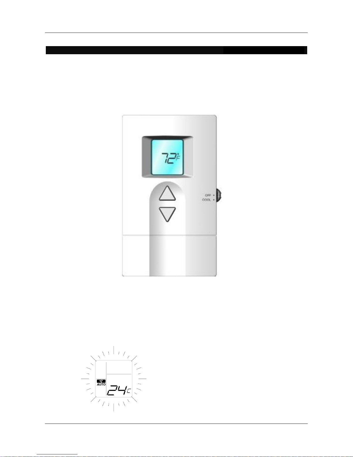
Fig. 1 Thermostat
Dimensions: 5¼” (H) x 3¼” (W)x 1¼” (D)
FEATURES
- Stylish design with continuously backlit LCD display.
- Slider switch allowing user to switch equipment on or off.
- User options and set point are retained in the event of lost power.
Back Lighting: The
thermostat features a
back light that will
illuminate all the time.
The user can easily see
the LCD screen under
dim light situation.
Vtronix
Vtronix LLC PO Box 267096, Weston FL 33326
Copyright © 2012 Vtronix Document no. 170306-170EQ Rev00
2
INSTALLATION
Read these instructions thoroughly before installing
product. Failure to follow these instructions could
damage the product or cause a hazardous condition.
Installer must be a trained, experienced service
technician. Check product for proper operation after
installation.
CAUTION
Damage to cooling system may occur. Disconnect
power and the thermostat wire from the equipment
while installing the thermostat.
Mounting Location.
Mount the thermostat approximately 5 ft. (1.5m)
above the floor in a location that is free from direct
flow of cold air from any supply air grilles, ducting
or from the equipment itself (for non-ducted
applications). Failure to locate thermostat mounting
as indicated will result in poor temperature control.
NOTE: Level thermostat mounting is for appearance
only and is not required for proper thermostat
operation.
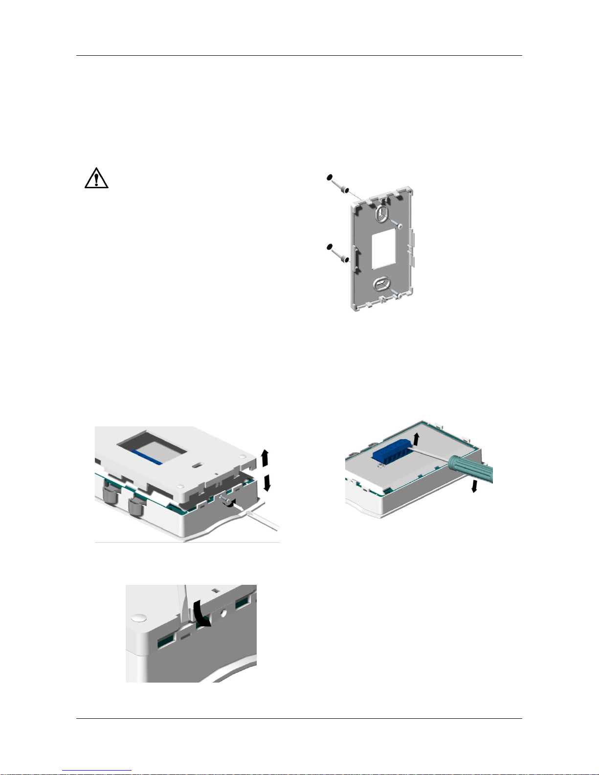
Mounting Thermostat
Take out the back plate by removing the locking
screw (if any) at the bottom of the thermostat. Use
flat head screw driver to unlock the snaps. Lift and
pull it up to remove back plate.
Using back plate as a guide, mark two mounting
holes on the wall. Drill two mounting holes. Place
anchors (provided) into the holes until flush with
the hole. Position back plate on the wall and pass
the wires from the equipment through the wiring
hole. Holding the back plate in place on the wall,
secure it to the wall using mounting screws
(provided).
Wiring
You will notice a 6-conductor terminal strip on
the back side of the thermostat (which can be
removed from the thermostat if needed as shown
in Figure 4). Four terminals are not operable.
Only the two operable terminals are required.
Loosen the terminal screws as needed.
The thermostat wire supplied with the ONAM
equipment is an 18-2 stranded cable. While the
wire is color coded, its connection to the
thermostat is not affected by polarity. Install one
conductor to one of the operable terminals and
install the second conductor to the other operable
terminal. Firmly tighten terminal screw when
finished.
Fig. 3.Installing
back plate
Fig. 2 Taking out back plate
Fig. 4 If needed, remove the terminal
strip by sliding it up and off the
thermostat body

Vtronix
Vtronix LLC PO Box 267096, Weston FL 33326
Copyright © 2012 Vtronix Document no. 170306-170EQ Rev00
3
Place the thermostat back on to the back plate
making sure that it is oriented correctly and then
snap it in place. Secure the thermostat by tightening
the screw provided to protect the thermostat from
unwanted access.
OPERATION
SYSTEM CHECKOUT
Slide mode switch to COOL. Using the ‘Up’ and
‘Down’ push keys, adjust the temperature to the
desired set point. If this is below the room
temperature, a star symbol is shown on the display. If
flashing, the compressor delay time is not yet
expired. If lit steady, equipment should energize.
ADVANCED SETUP
The thermostat has been factory set to display the
temperature in degrees Fahrenheit. To change to
the Celsius scale, the factory settings must be
changed and this can be done as follows:
Set the temperature set point to 52F (or 11 C)
Press the ‘Up’ and ‘Down’
keys simultaneously to
enter installer setup.
Press the ‘Up’ key once;
display will read “OP:02”.
You can now toggle
between F and C by
using the ‘Down’ arrow.
To exit setup, press the ‘Up’ key a number of
times (skipping parameters OP:03 to OP:06). The
change to the setting will be saved and the
thermostat will exit to the normal operating mode.
NOTE: After return to normal operation, change
the set point to the desired temperature; otherwise
the default set point ( 70 F or 21C) will be used.
OR
Fig. 5. Installing and securing the thermostat
Minimum Off Timer
If the thermostat calls for
operation while the minimum
off timer is not expired, the
star symbol keeps flashing.
Temperature Setting
Use the ‘Up’ or ‘Down’ push
keys to set temperature.
The display shows set point
value flashing for 5 seconds
before returning to the room
temperature.
Note: There are a total of six factory
parameters. Do not alter any except
“OP:02”. If a change is accidentally made to
any of the other parameters, ensure that
“OP:04” is set to “00” and “OP:05” is set to
“03”.

Vtronix
Vtronix LLC PO Box 267096, Weston FL 33326
Copyright © 2012 Vtronix Document no. 170306-170EQ Rev00
4
 Loading...