

Page 1
Vtronix
1
TE86S,TE86SB
Digital Thermostat
INSTALLATION MANUAL
APPLICATION
The TE86S Thermostat provides universal replacement of single-stage, 24Vac (20 mA to 1.5A) thermostats
used in electric, gas, and oil heating and cooling systems. This thermostat is mercury free and requires no
batteries. The thermostat also can be used to control single stage heat pumps.
The TE86S uses advanced proportional plus integral (P+I) control for optimum temperature control and
comfort.
Table 1. Description of Thermostat.
Model Mounting System Selection Fan Selection Powering
Method
TE86SVERTICALCOOL-OFF-HEATON-AUTOPower StealingNo Backlight
TE86SBVERTICALCOOL-OFF-HEATON-AUTOPower StealingBacklight
Backlight
FEATURES
- Stylish design, replaces Honeywell T834C, White Rodgers 1E56 or Lux PSD150.
- LCD display with back lighting lit all the time (TE86SB).
- Power stealing for universal replacement. No common wire required. No batteries.
- Heat cycle rate can be selected (1,3,4,5,6,9,12) by software to suit many heating applications.
- Heating / cooling damper output to control either dampers or heat pump reversing valve.
- User options and set point are retained in the event of lost power.
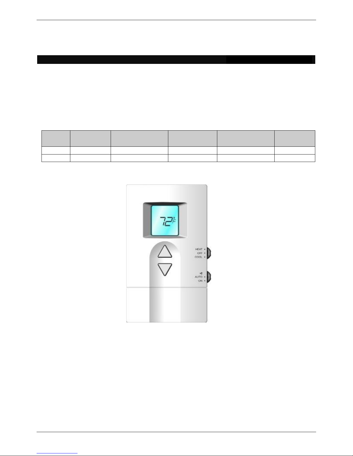
Fig. 1.Thermostat
Page 2
Vtronix
2
SPECIFICATIONS
Table 2. Thermostat specifications.
Power
Power Supply24 Vac nominal, 18-30 Vac, 50/60 HZ.
Electrical Rating
Heating rating
Cooling rating
Fan rating
Note: The fan load plus the higher of the heating or
cooling load must not exceed 1.5 Amp continuous
TEMPERATURE RATINGS
Temperature setting range
Ambient temperature range
Shipping temperature range
OPERATING RELATIVE HUMIDITY
CYCLE RATES
Cooling mode
Heating mode
0.02 to 1.5 A continuous
0.02 to 1.5 A continuous
0.02 to 0.5 A continuous
40 to 99 °F (4 to 37 °C)
40 to 110 °F (4 to 43 °C)
14 to 140 °F (-10 to 60 °C)
5 to 90% RH, non-condensing
3 Cycles Per Hour
1,3,4,5,6,9,12 Selectable Cycles Per Hour
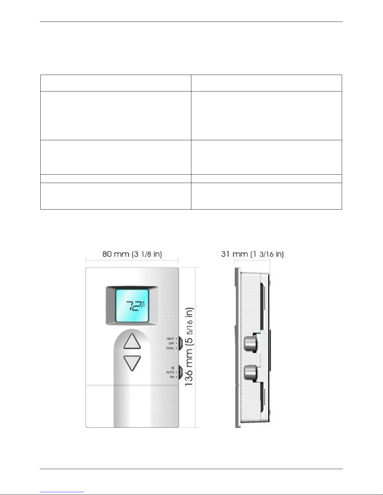
DIMENSION
Fig. 2.Thermostat dimension
Page 3
Vtronix
3
electrical code located near each terminal.
back plate
back plate
INSTALLATION
Read these instructions thoroughly before installing
product. Failure to follow these instructions could
damage the product or cause a hazardous condition.
Check the voltage and current ratings on the product
to ensure that it is suitable for your application.
Installer must be a trained, experienced service
technician. Check product for proper operation after
installation.
CAUTION
Damage to heating and cooling system may occur.
Disconnect power from the equipment at the main
breaker/fuse block while installing the thermostat.
Mounting Location.
Mount the thermostat approximately 5 ft. (1.5m)
above the floor in a location that is free from direct
sunlight, heat from appliances, hot or cold air from
ducts, concealed pipes and chimneys, and drafts or
dead spots behind doors or in corners. Do not mount
on exterior wall, if possible. Failure to locate
thermostat mounting as indicated will result in poor
temperature control.
NOTE: Level thermostat mounting is for appearance
only and is not required for proper thermostat
operation.
Using back plate as a guide, mark two mounting
holes on the wall. Drill two mounting holes. Place
anchors (provided) into the holes until flush with
the hole. Position back plate on the wall and
thread the wires from the heating and cooling
equipment through the wiring hole. Holding the
back plate in place on the wall, secure it to the
wall using mounting screws (provided).
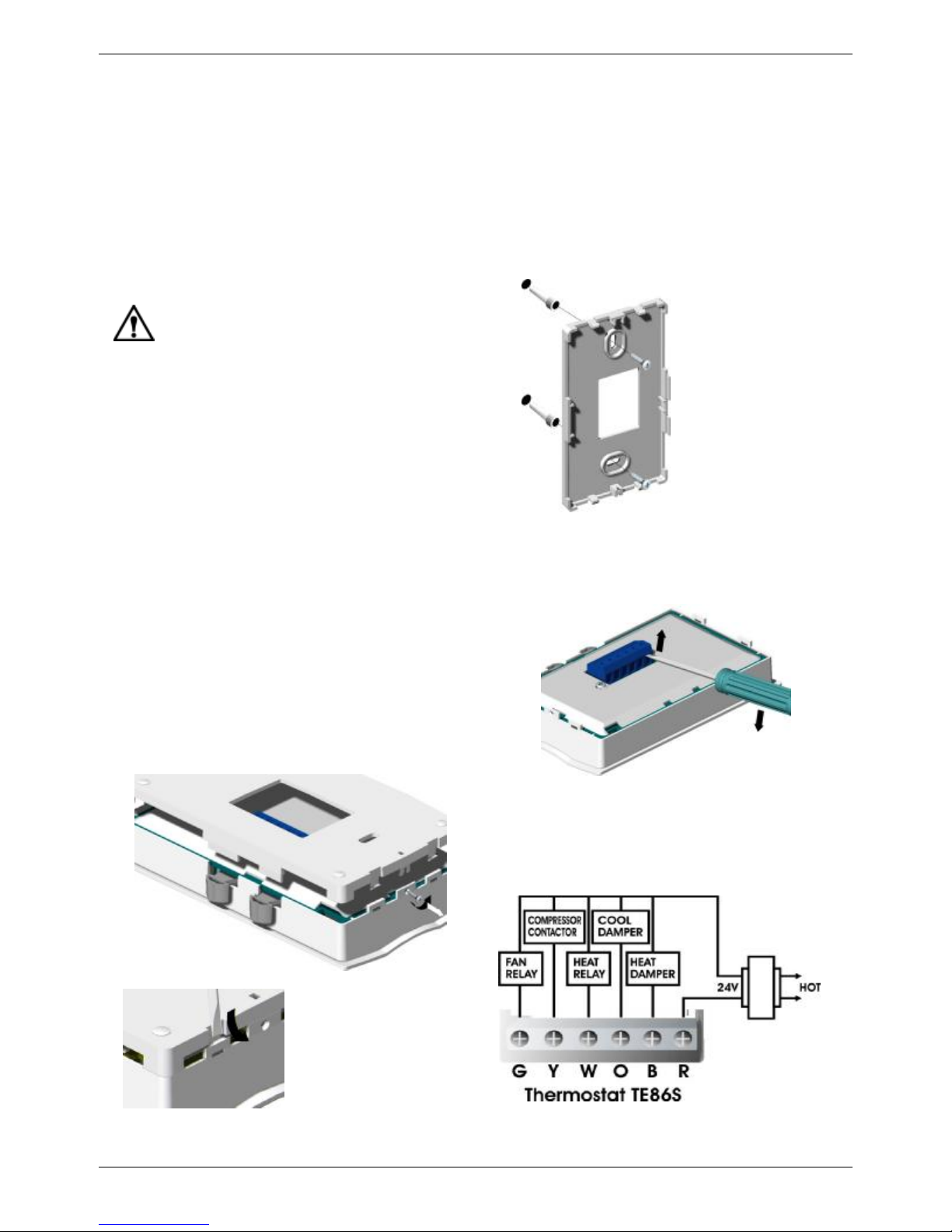
Fig. 4.Installing
Wiring
Pull the connector from the back of thermostat by
inserting screw driver at the base of connector and
gently lift up.
Mounting Thermostat
Take out the back plate by removing the locking
screw (if any) at the bottom of the thermostat. Use
flat head screw driver to unlock the snaps. Lift and
pull it up to remove back plate.
Fig. 3.Taking out
Fig. 5 Lifting the connector
Color-coded 18-22 gauge wire is recommended
for wiring. All wiring must follow local
Fig. 6a.Wiring diagram.
Page 4
Vtronix
4
*Note: Set-up
*Note: Set-up
HEAT PUMP WITH
HEAT ACTIVE
REVERSING VALVE
HEAT PUMP WITH
COOL ACTIVE
REVERSING VALVE
switch must be
in E position.
Set-up switch (E/F)
WARNING
Fire Hazard.
Failure to set the set-up switch to the E position
when electric resistance heat is used may result
in the overheating of the electric heater elements
due to improper fan operation.
The set-up switch is an internal switch (E,F)
located near the wiring terminals. It is used to
select proper fan operation for the heating
system being used.
q The E position is for electric heat and single
stage heat pump applications.
q The F position is for fuel applications.
switch must be
in E position.
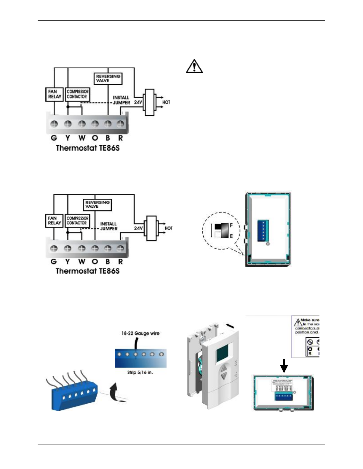
Fig. 6b. Wiring Diagram for
single stage heat pump.
Loosen the terminal screw, strip the wire and
connect the wire as shown in fig 7. Firmly tighten
terminal screw when finished.
Fig. 7. Connecting wire.
Fig. 8. Setup switch.
Place the terminal back to the thermostat, make
sure it has the same orientation like in the picture
described at the back. Snap the thermostat to its
back plate.
Fig. 9. Installing thermostat.
Page 5
Vtronix
5
Now follow the following steps to change each of the
and
Secure the thermostat by tightening the screw
provided to protect the thermostat from unwanted
access.
Fig. 10. Secure the front cover.
INSTALLER SETUP
The following instructions provide information to
test the heating / cooling equipment and to change
operating parameters from the factory settings.
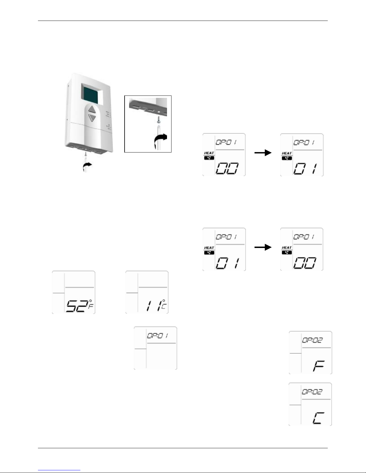
Testing Heating / Cooling Equipment. (OP:01)
While in the installer setup, slide the mode switch to
heat to operate the heating equipment or cool to
operate the cooling equipment. The display will show
either 00 or 01 on the lower right area and either heat
or cool as selected by the mode switch.
a. If the equipment is off, press Ñ key to turn it on
(if not, check the wiring or the equipment).
Example display showing
Heat equipment is off.
b. Press Ñ key again to turn off.
Example display showing
Heat equipment is on.
Enter Installer Setup
a. Use D or Ñ key to set the temperature set point
to 52°F (or 11 °C).
OR
b. Press D
simultaneously to enter installer
setup.
settings. Each time you press D key, you will advance
to the next operating parameter. To go back you must
re-enter the installer set up as described above.
Ñ key
Example display showing
Heat equipment is on.
Setting °C / °F Indication. (OP:02)
While in the installer setup,
a. Press D key, the display will
show °F/°C indication.
b. Press Ñ key to change °F or °C
indication.
NOTE: Factory setting
is °F indication.
Example display showing
Heat equipment is off.
Page 6
Vtronix
6
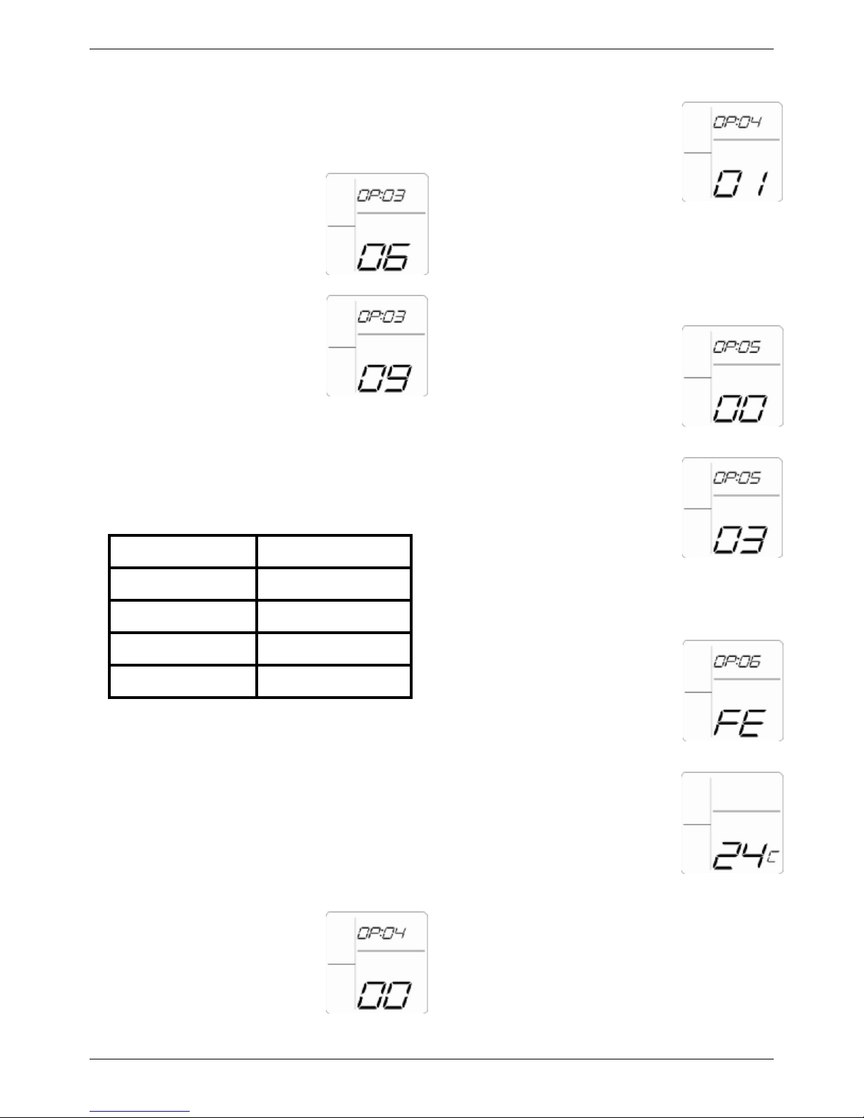
Setting Heating Cycle Rate. (OP:03)
equipment manufacturer for proper use.
operating mode.
In cooling, the cycle rate is fixed at 3 Cycles per
hour. To set the cycle rate in heating; while in
installer setup,
a. Press D key, the display will
show the heat cycle rate.
b. Press Ñ key to change the heat
cycle rate to 1,3,4,5,6,9 or 12
cycles per hour.
Note: The default is set at 6 cycle per hour.
Table 4 is the recommended cycle rate. The
installer should consult with the heating
Table 4. Recommended cycle rate (CPH).
SYSTEMCPH SETTING
b. Press Ñ key to change algorithm.
0 = Normal algorithm (default).
1 = Aggressive algorithm.
Setting Cooling Delay Time. (OP:05)
In some case there is a necessity to delay the
operation of the cooling equipment for protection
purpose. While in the installer setup,
a. Press D key. The display will
show cooling delay time.
b. Press Ñ key to select the cooling
delay time (0,3,5 minutes).
NOTE : The default setting is 3
minute.
Steam Gravity1
Hydronic heat3
Gas or Oil forced air6
Electric heat9
Note: If the equipment manufacture recommends
a different rate use the rate specified by the
equipment manufacture.
Setting cooling algorithm. (OP:04)
The cooling algorithm can be selected as normal or
aggressive. For aggressive, the system will cool down
the room to setting point faster than normal algorithm.
However, an overshoot might occurred in some
situations.
a. Press D key to show the cooling
algorithm.
Configuration Checkout. (OP:06)
Press D key, the current
configuration is displayed.
This information is for factory use
only.
Exit Installer Setup.
a. Press D key again to save all
settings and exit to the normal
NOTE: After return to normal operation, change
the set point to the desired room temperature,
otherwise the default set point ( 70 °F or 21°C)
will be used.
Page 7
Vtronix
7
OPERATION
System Setting
Use mode switch for selecting system operation.
q Cool : The thermostat controls the cooling
system.
q Heat : The thermostat controls the heating
system.
q Off : Both heating and cooling are off.
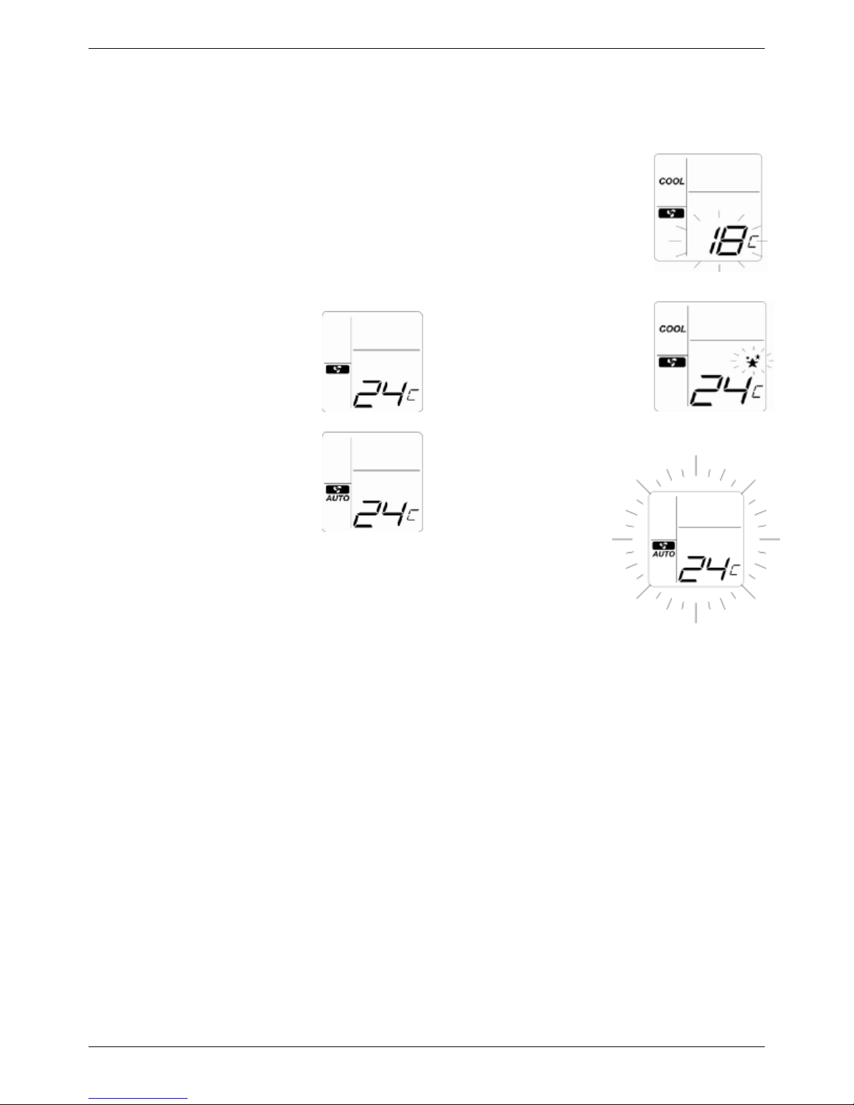
Fan Setting
Fan switch settings are
On : Fan symbol is indicated on
the display. The fan runs
continuously. Used to improve air
circulation and air quality.
Auto : Fan and Auto symbols are
indicated on the display.
For cooling mode:
The fan starts and stops with
cooling equipment.
For heating mode:
q If setup switch is at ‘ F’ position, the fan is
controlled directly by the heating equipment.
q If setup switch is at ‘ E’ position, the fan starts
and stop with heating equipment.
Temperature Setting
Use D or Ñ key to change
temperature setting in a range
of 40 to 99 °F (or 4 to 37 °C).
The display shows set point
value flashing for 5 seconds
before returning to the room
temperature.
Minimum Off Timer
For cooling, when the thermostat
calls for operation while the
minimum off timer is not expired,
the star symbol keeps flashing.
Back Lighting
( TE86SB )
The thermostat features
a back light that will
illuminate all the time.
The user can easily see
the LCD screen under
dim light situation.
SYSTEM CHECKOUT
Cooling Checkout
WARNING ! Do not operate in cooling mode when the outdoor temperature is below 50 °F ( 10 °C)
otherwise the compressor might be damaged.
1. Slide mode switch to COOL, O terminal will get energized.
2. Pressing Ñ key to lower the set point below room temperature. The star symbol is shown on the display.
If flashing, the compressor delay time is not yet expired. If lit steady, the compressor is on and terminal
Y is energized.
3. Press D key until set point is higher than room temperature. The star symbol is removed. The compressor
is off and Y terminal is de-energized.
Page 8
Vtronix
8
CGG
Heating Checkout
1. Slide mode switch to HEAT, B terminal will get energized.
2. Press D key until the set point is higher than room temperature. The star symbol is shown on the display.
The heating equipment is on and terminal W is energized.
3. Press the Ñ key until set point is lower than room temperature. The star symbol is removed. The heating
equipment is off and W terminal is de-energized.
Fan Checkout
1. Slide FAN switch to ON position. The G terminal is energized and the fan should always be running.
2. Slide FAN switch to AUTO position,
q In cooling mode, the fan starts and stops with the cooling equipment.
q In heating mode when setup switch is in the F position, the fan is controlled directly by the heating
equipment and may start a few minutes after the heating equipment turns on. When setup switch is in the
E position, the fan starts and stops with the heating equipment.
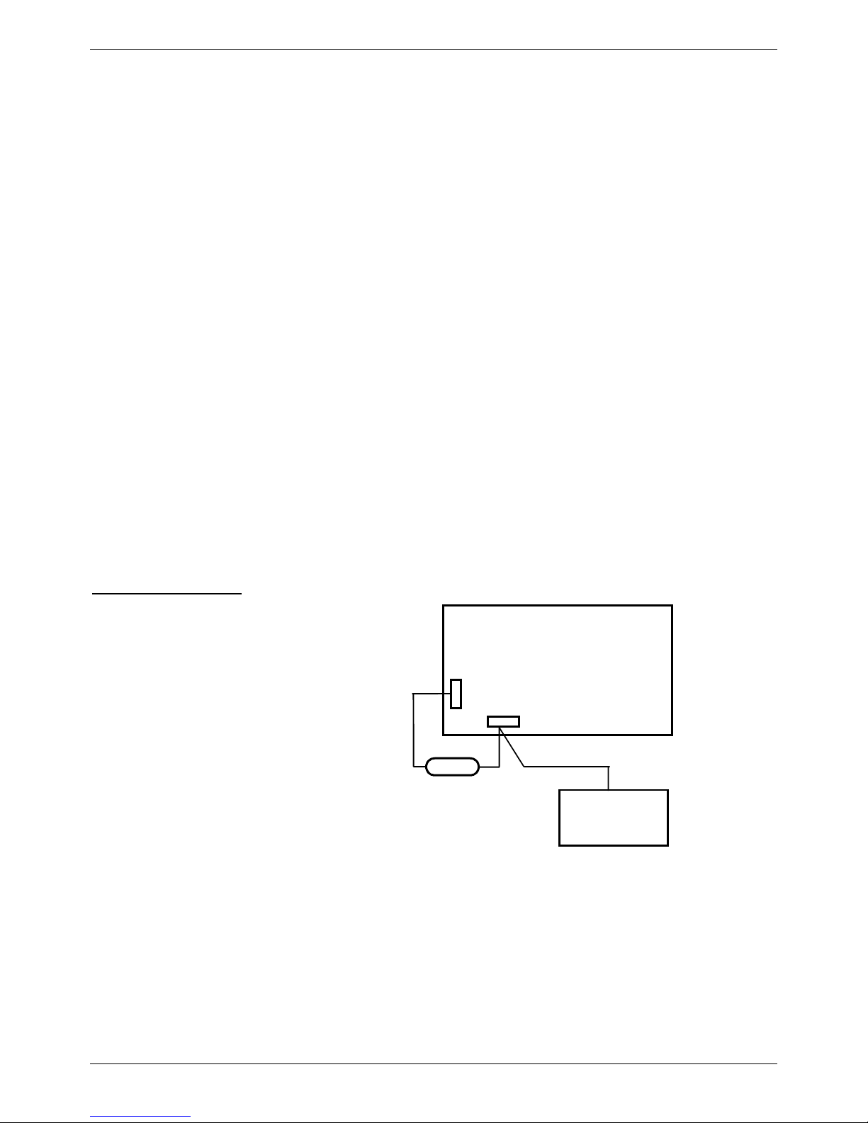
Application Note
Attached 1000 ohm, 3 watt resistor is used in certain applications to assure compatibility with power stealing
thermostats where Fan does not come ON during call for Heat or Cool. Note that resistor has to be installed
at the fan terminals and not at thermostat terminals.
To install the Resistor
1. Disconnect power supply.
2. Connect the resistor leads to the terminals
Air Handler Fan Board
as shown in the drawing.
3. Turn on the system power.
1000 Ohm
3Watt
Resistor
Thermostat
VTRONIX, LLC 318 Indian Trace #327, Weston, FL 33326
 Loading...