

Page 1

Vtronix
1
TE56M, TF56M
Thermostats
INSTALLATION MANUAL
APPLICATION
The TE56M and TF56M Thermostats provide universal replacement of single-stage, 24Vac (10 mA to 1.5A)
thermostats used in electric, gas, and oil heating and cooling systems.
These thermostats are mercury free and require no batteries.
The TE56M and TF56M use advanced proportional plus integral (P+I) control for optimum temperature
control and comfort.
Model Mounting System Selection Fan Selection Powering Method
TE56M Vertical COOL-OFF-HEAT ON-AUTO Power Stealing
TF56M Horizontal COOL-OFF-HEAT ON-AUTO Power Stealing
SPECIFICATIONS
ELECTRICAL RATINGS
Power Supply
Load Current Range
24 Vac nominal, 18-30 Vac, 50/60 HZ.
10 mA – 1.5A.
TEMPERATURE RATINGS
Temperature setting range
40 to 99 °F (4 to 37 °C)
Ambient temperature range
40 to 110 °F (4 to 43 °C)
Shipping temperature range
-20 to 120 °F (-29 to 49 °C)
OPERATING RELATIVE HUMIDITY
5 to 90% RH, non-condensing
CYCLE RATES
Cooling mode 4 Cycles per hour
Heating mode 6 Cycles per hour
TF56M
TE56M
Fig. 1. TE56M and TF56M Thermostats.
Page 2
Vtronix
2
INSTALLATION
Read these instructions thoroughly before installing
product. Failure to follow these instructions could
damage the product or cause a hazardous condition.
Check the voltage and current ratings on the product
to ensure that it is suitable for your application.
Installer must be a trained, experienced service
technician. Check product for proper operation after
installation.
CAUTION
Damage to heating and cooling system may occur.
Disconnect power from the equipment at the main
breaker/fuse block while installing the thermostat.
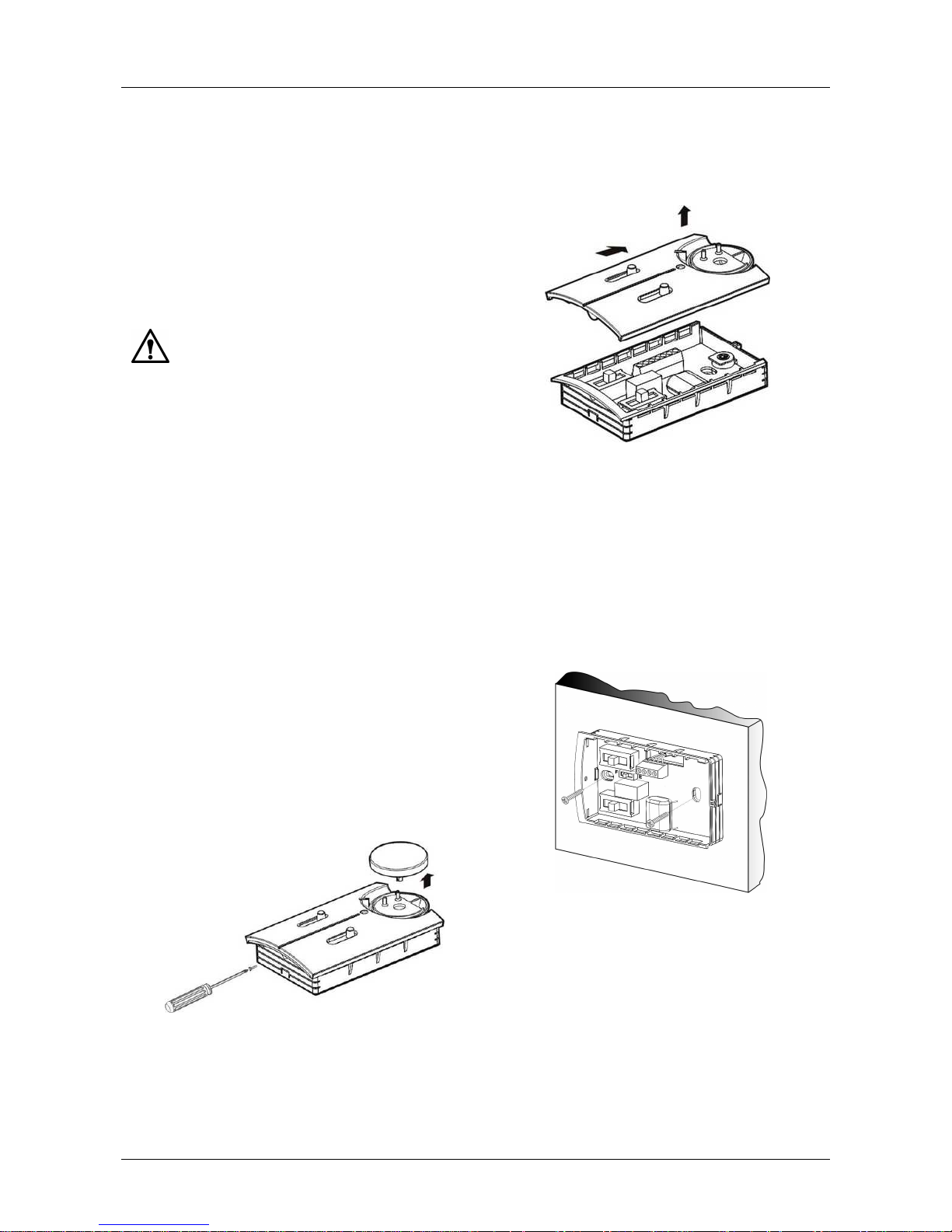
Take out the front cover by sliding it to the right
and remove. See Fig.3.
Mounting Location
Mount the thermostat approximately 5 ft. (1.5m)
above the floor in a location that is free from direct
sunlight, heat from appliances, hot or cold air from
ducts, concealed pipes and chimneys, and drafts or
dead spots behind doors or in corners. Do not mount
on exterior wall, if possible. Failure to locate
thermostat mounting as indicated will result in poor
temperature control.
NOTE:
Level thermostat mounting is for appearance
only and is not required for proper thermostat
operation.
Using the thermostat base as a guide, mark two
mounting holes on the wall. Drill two mounting
holes. Thread the wires from the heating and
cooling equipment through the wiring hole on the
thermostat base. Holding the base in place on the
wall, secure it to the wall using appropriately
sized screws (Fig. 4).
Mount and Wire the Thermostat
Remove the locking screw at the side of the
thermostat. Pull the temp. knob upward and remove it.
Fig. 2. Remove temperature setting knob.
Fig. 3. Remove thermostat cover.
Fig. 4. Mount thermostat on wall.
Page 3
Vtronix
3
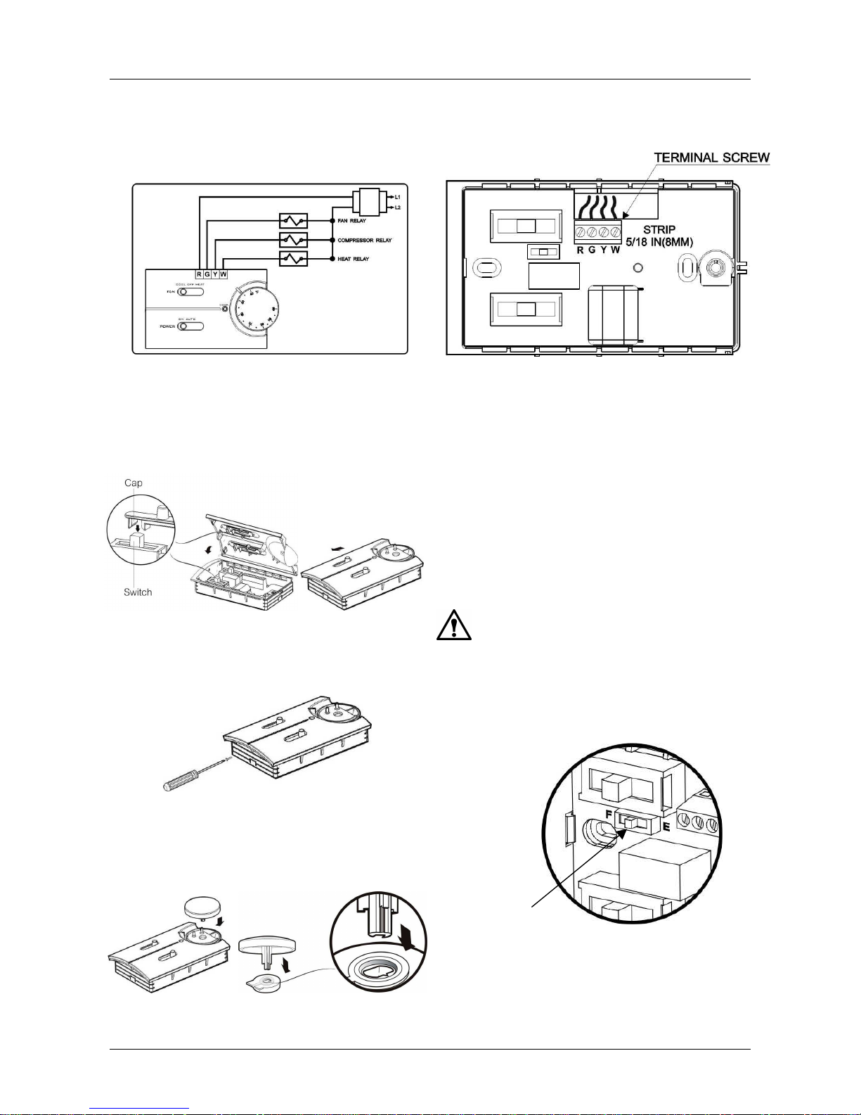
With the cover removed, connect the wires from the heating/cooling equipment to the terminals on the
thermostat base. See wiring diagram (Fig. 5) for location of thermostat terminals.
Put the front cover back to the thermostat by having
POWER
&
FAN
switches locked by the caps and then
slide to the left.
Secure the front plate by using the locking screw.
Insert the temp. knob to the thermostat, make sure it
is put with the same alignment & position as shown.
OPERATION
Set-up Switch
The set-up switch is an internal switch (E, F) that is
located on the thermostat base. See Fig. 9. It is used
to select the type of heating system being used.
The E position is for electric heat applications.
The F position is for gas or oil heat applications.
WARNING
Fire Hazard.
Failure to set the set-up switch to the E position
when electric resistance heat is used may result in
the overheating of the electric heater elements due
to improper fan operation
Fig. 5. Connect system wires to thermostat terminals (strip 5/16 IN).
Fig. 6. Put front cover back & Slide switches to the left.
Fig. 7. Secure the front plate.
Fig. 9. Location of set-up switch on thermostat base.
Set-up switch
Fig. 8. Verify thermostat shaft is properly aligned.
Page 4
Vtronix
4
System Switch
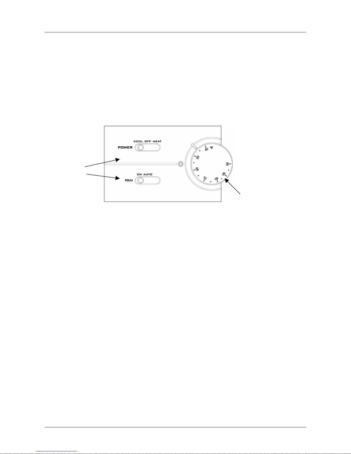
The system switch is located on the thermostat cover and is used to select heating, cooling or to turn off
power to the thermostat.
In the COOL position, the system is operating in cooling mode.
In the HEAT position, the system is operating in heating mode.
In the OFF position, power is turned off to the thermostat.
Fan Switch
The fan switch is located on the thermostat cover. See Fig.10. The setting positions are ON and AUTO.
In the ON position, the fan runs continuously.
In the AUTO position, the fan runs when the cooling or heating equipment is in operation.
Temperature Setting
The temperature setting range is 40 to 99 °F. The temperature can be adjusted using the temperature setting
knob on the thermostat cover. See Fig. 10.
Heating/Cooling Equipment Status
The LED on the front cover indicates the ON/OFF status of the cooling and heating equipment. See Fig.10.
Fig. 10. System and fan switch positions, temperature setting knob, and equipment status LED location.
Temperature setting knob
System and Fan switches
VTRONIX, LLC 318 Indian Trace #327, Weston, FL 33326
Copyright © 2002 Vtronix Document no. 170060-520E Rev.00
 Loading...