

Vtronix TF85L –10011, TF85L - 11011, T200, T201 Installation Manual
Vtronix
TF85L –10011 (T200) Manual Changeover
TF85L - 11011 (T201) Auto Changeover
Digital Room Thermostat
INSTALLATION MANUAL
APPLICATION
The TF85L Thermostat provides 24VAC single stage temperature control of 2 pipe and 4 pipe fan-coil
applications with automatic control of a 3 speed fan along with manual heat/cool changeover.
The TF85L Thermostat is mercury free and requires no batteries. All set points are retained permanently in
non-volatile memory in case of a power interruption.
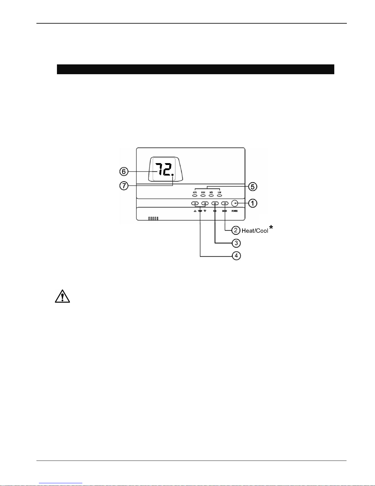
* This button shows Heat/Cool status for Auto Changeover Model. Heat/Cool mode can not be changed.
Fig.1. Digital Room Thermostat.
WARNING
• Improper installation, adjustment, alteration, service, maintenance or use can cause explosion, fire,
electrical shock or other conditions which may cause personal injury, death or property damage.
• Observe all warning and caution notices in this document and those posted on the equipment.
• Wear safety glasses, gloves and protective clothing.
• Do not operate equipment or apply electrical power without panels in place.
• Normal system operation will cause some components and surfaces to become hot and can cause burns.
• Before installing, modifying or servicing system, main electrical disconnect switch must be in the OFF
position. There may be more than one disconnect switch. Lock out and tag switches with a suitable
warning label. Electrical shock can cause personal injury or death.
• All electrical power should be turned off when servicing or repairing electrical components. Extreme
caution should be observed when trouble shooting electrical components when power is applied.
Observe all warning notices posted on equipment.
1
Vtronix
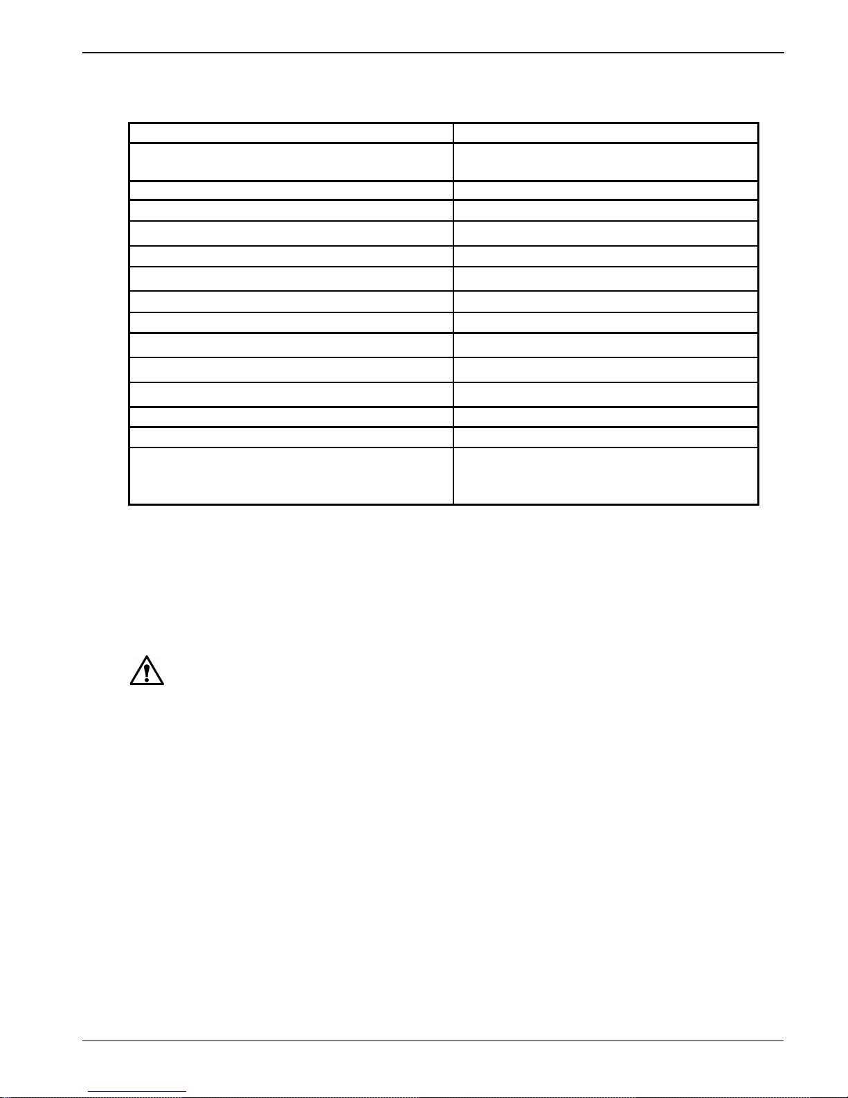
SPECIFICATIONS
POWER SUPPLY
24 VAC system 18 – 30 VAC, 50/60 Hz
TEMPERATURE :
Temperature accuracy
±
1.8 °F
Storage temperature 32 – 158 °F
Ambient temperature
50 – 122 °F
Setting temperature range
64 – 85 °F
Deadband (Auto changeover model)
± 1 °
F of Setpoint
HEAT and COOL RELAY : ( P1, P2)
Rating (resistive load)
• Maximum switching capacity
3 A 277 VAC
• Delay Time
1 minute or 3 minute (default)
FAN RELAY: (P3, P4, P5)
Rating (resistive load)
• Maximum switching capacity 2 A 277 VAC
3 A 125 VAC
INSTALLATION
Read these instructions thoroughly before installing product. Failure to follow these instructions could
damage the product or cause a hazardous condition. Check the voltage and current ratings on the product to
ensure that it is suitable for your application. Installer must be a trained, experienced service technician.
Check product for proper operation after installation.
CAUTION
Damage to heating and cooling system may occur. Disconnect power from the equipment at the main
breaker/fuse block while installing the thermostat.
Mounting Location
Mount the thermostat approximately 5 ft. (1.5m) above the floor in a location that is free from direct
sunlight, heat from appliances, hot or cold air from ducts, concealed pipes and chimneys, and drafts or dead
spots behind doors or in corners. Do not mount on exterior wall, if possible. Failure to locate thermostat
mounting as indicated will result in poor temperature control.
Note : Level thermostat mounting is for appearance only and is not required for proper thermostat operation.
2
 Loading...