

Page 1
User Manual
VTRON LCD Display Panel
V1.0
VTRON
http:// www.vtron.com
E-Mail: info @ vtron.com
All rights reserved
Page 2
User Manual VTRON LCD Display Panel
This manual is the copyright property of VTRON. Without prior written approval from
VTRON, any part of this manual shall not be duplicated or distributed in any way or
by any means.
This manual is subject to changes without prior notice.
This product may allow you to use the third party’s software or upload, download the
third party’s works, including articles, images, video or software, but VTRON does not
own or provide such third party’s works. Your use of the above-mentioned third party’s
works means that you agree to use such works without infringing or breaching the
rights of the third party, and VTRON does not assume any liability for your use.
VTRON and Digicom are the registered trademarks of VTRON. Windows is the
trademark or registered trademark of Microsoft in the USA and/or other countries
(regions). Other product names and company names mentioned in this document may
be the trademarks of their respective owners.
Notice
This manual is designed for the introduction to the LCD display panel developed by
VTRON. The specific configurations and functions shall be in accordance with the
purchase contracts signed with the customer. The functions and display interface of the
product you order might differ from those introduced in this manual.
Statement
Products as introduced in this manual are Class A products that may cause radio
interferences in domestic environment. Practical measures should be taken when
necessary.
Currently, the use of LCD display panel shall not last for more than 20 hours each
day due to the technical limitation of the panel manufacturers. Otherwise, the long time
use may cause some aging and Black Mura problems, which may result in some
damages to the panel. In such case, VTRON has the duty to help repair the product. But
VTRON assumes no liability for such kind of damages, so the necessary fee is needed
for the repair.
Page 3
User Manual VTRON LCD Display Panel
This product has passed strict tests before delivery. However, improper use
may cause electric shock or fire. To ensure safety, extend the service life of this
product and maximize its performance, please read carefully the following items
before using this product, and strictly observe the relevant safety precautions.
If the following situations appear, plug off the power connector from the socket and
turn to qualified technician for repair:
a. The power cable or power connector is damaged or worn out;
b. The panel drops down to the floor or its
cover is damaged;
c. Exception occurs, and the panel still
cannot operate normally even when you
have acted according to the instructions.
d. Foreign object or liquid falls into the unit;
e. Unusual noise or smell gives out;
Inside the panel, there exists high voltage,
and there are no user serviceable
components. To avoid the relevant danger,
please do not open the cover. If repair is
needed, please turn to the qualified
technician.
Safety Precautions
!
Page 4

User Manual VTRON LCD Display Panel
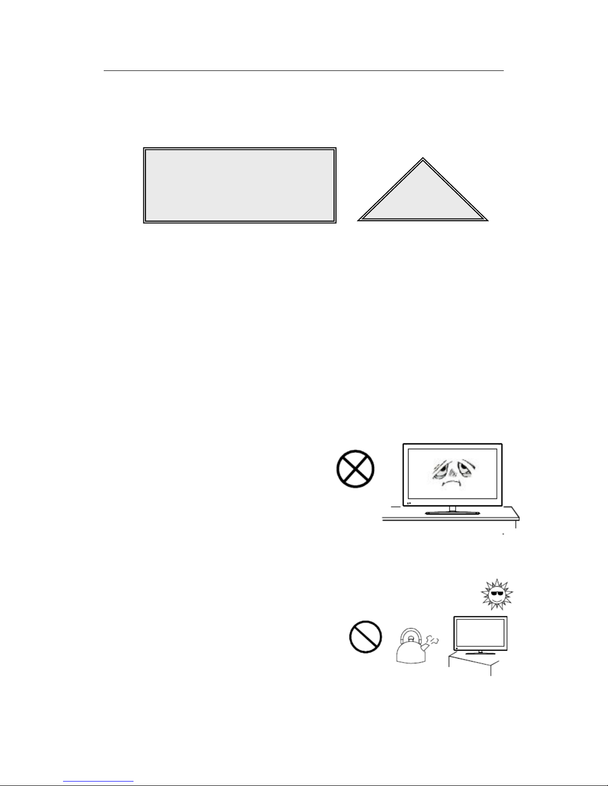
Locate the panel in the place with good ventilation, moderate temperature and free
from dampness and direct sunshine.
The opening on the enclosure is used for the
heat dissipation of the components inside.
Pay attention not to block the openings when
locating the unit.
Do not place the unit inside any embedded equipment, unless there is any good
ventilation device.
To avoid the falling of the panel, do not place the
panel on any uneven surface.
Do not use the panel near the water source, in the
damp basement or other similar environment.
To avoid unnecessary accidents, please cut off
the power supply during lightning storms.
Page 5

User Manual VTRON LCD Display Panel
Contents
1. Display Panel Overview ............................................................................................. 1
1.1 System Features and Functions ................................................................................................... 1
1.2 Technical Parameters .................................................................................................................. 2
1.2.1 Display Panel Parameters..................................................................................................... 2
1.2.2 Interface Parameters ............................................................................................................. 5
1.2.3 Product Outline Dimensions ................................................................................................ 6
1.3 Interface Overview.................................................................................................................... 11
2. Remote Control ......................................................................................................... 12
3. OSD Menu Operation .............................................................................................. 15
4. Connection Diagram for Display Panel (2×2) ........................................................ 21
5. Loop Connection Diagram ....................................................................................... 22
6. Installation of Display Panel .................................................................................... 23
7. Use of Display Panel ................................................................................................. 24
7.1 System Startup/Shutdown ......................................................................................................... 26
7.2 Display Signal Source ............................................................................................................... 27
8. Daily Maintenance .................................................................................................... 27
9. Contact us .................................................................................................................. 29
Page 6

User Manual VTRON LCD Display Panel
- 1 -
1. Display Panel Overview
1.1 System Features and Functions
L-xxxxx8 products are LCD display panels developed for large-screen video wall
system to realize display of all the input signals.
L-xxxxx8 LCD display panels have the following functions and features:
Support the input of DRGB signal.
Support serial port loop control.
Support entire wall on/off function.
Automatic parameter saving function, able to memorize the adjusted
parameters.
Able to normally display the picture even when the display signal input cable
is plugged out and then plugged in.
Support large-screen display wall application administration software VCMS
(optional).
The VCMS (VTRON LCD Display Management System) software is the
application administration system developed, designed and produced by
VTRON for the large-screen video wall. It is used to control the hardware
equipment in the large-screen display wall system so as to realize the
administration and control of various signal windows and application
windows of the wall. For the detailed configuration and operation instruction
of VCMS, please refer to the user manual of VCMS software.
Page 7
User Manual VTRON LCD Display Panel
- 2 -
1.2 Technical Parameters
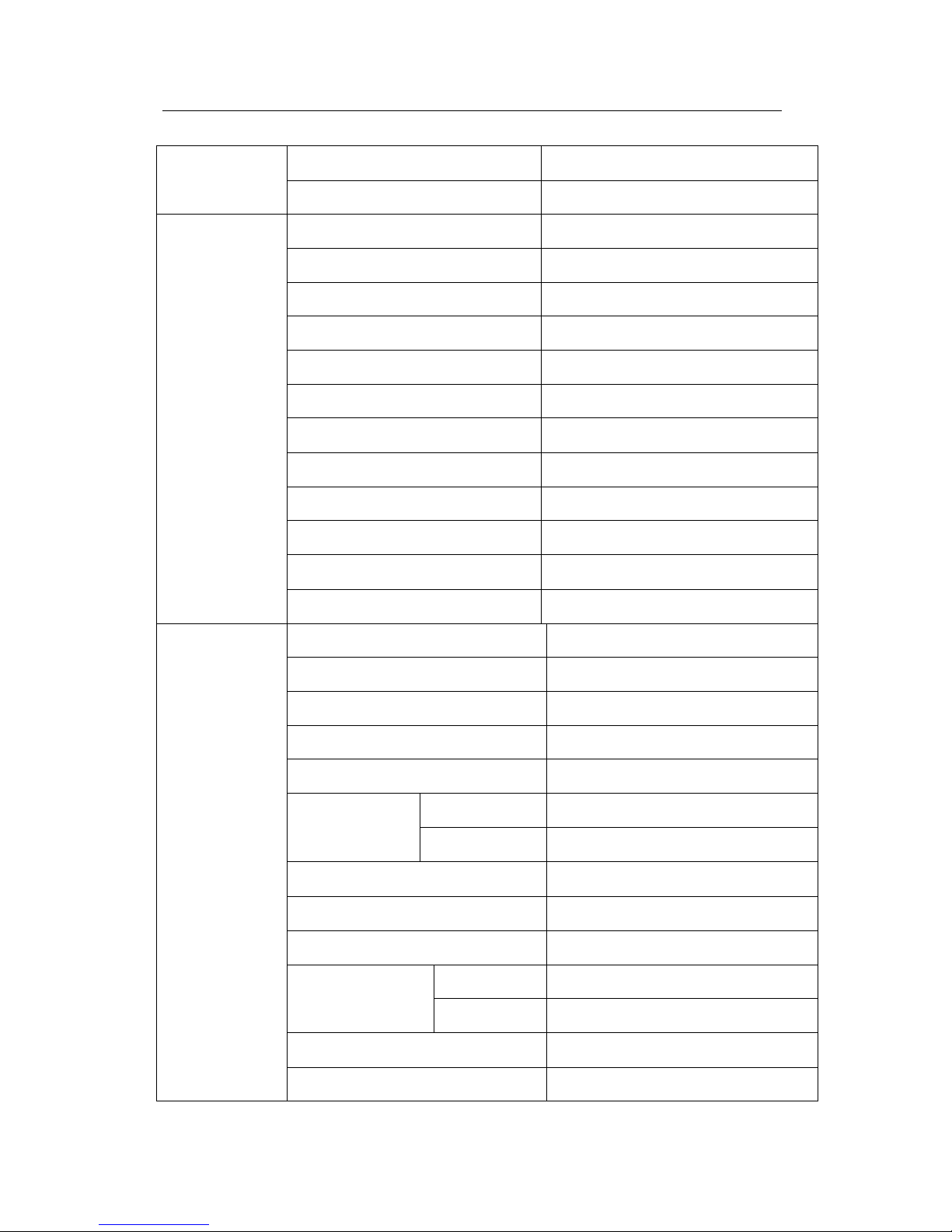
1.2.1 Display Panel Parameters
L-PH4618/
L-PH4618(L)
display panel
Screen size
46″
Screen aspect ratio
16:9
Physical resolution
1920×1080
Dot pitch (mm)
0.530(H) ×0.530 (V)
Display area (mm)
1018.08 (H) × 572.67 (V)
Brightness
L-PH4618(L)
Min.400cd/m2 ;Typ.500cd/m2
L-PH4618
Min.600cd/m2 ;Typ.700cd/m2
Contrast ratio
Min.2500:1 ;Typ.3500:1
Viewing angle (H/V)
Min.178°/178°
Service life
50000 hours
Power
consumption
L-PH4618(L)
Max:130W
L-PH4618
Max:180W
Power supply
100~240VAC,50~60Hz
Weight
21 Kg
L-PH4628/
L-PH4628(L)
display panel
Screen size
46″
Screen aspect ratio
16:9
Physical resolution
1920×1080
Dot pitch (mm)
0.530(H) ×0.530 (V)
Display area (mm)
1018.08 (H) × 572.67 (V)
Brightness
L-PH4628(L)
Min.400cd/m2 ;Typ.500cd/m2
L-PH4628
Min.600cd/m2 ;Typ.700cd/m2
Contrast ratio
Min.2500:1 ;Typ.3500:1
Viewing angle (H/V)
Min.178°/178°
Service life
50000 hours
Power
consumption
L-PH4628(L)
Max:100W
L-PH4628
Max:120W
Page 8
User Manual VTRON LCD Display Panel
- 3 -
Power supply
100~240VAC,50~60Hz
Weight
21 Kg
L-PH5518(L)
display panel
Screen size
55″
Screen aspect ratio
16:9
Physical resolution
1920×1080
Dot pitch (mm)
0.630(H) ×0.630 (V)
Display area (mm)
1209.6 (H) × 680.4 (V)
Brightness
Min.400cd/m2 ;Typ.500cd/m2
Contrast ratio
Min.2500:1 ;Typ.3500:1
Viewing angle (H/V)
Min.178°/178°
Service life
50000 hours
Power consumption
Max:220W
Power supply
100~240VAC,50~60Hz
Weight
27 Kg
L-PH5528/
L-PH5528(L)
display panel
Screen size
55″
Screen aspect ratio
16:9
Physical resolution
1920×1080
Dot pitch (mm)
0.630(H) ×0.630 (V)
Display area (mm)
1209.6 (H) × 680.4 (V)
Brightness
L-PH5528(L)
Min.400cd/m2 ;Typ.500cd/m2
L-PH5528
Min.600cd/m2 ;Typ.700cd/m2
Contrast ratio
Min.3000:1 ;Typ.4000:1
Viewing angle (H/V)
Min.178°/178°
Service life
50000 hours
Power
consumption
L-PH5528(L)
Max:220W
L-PH5528
Max:240W
Power supply
100~240VAC,50~60Hz
Weight
27.5 Kg
Page 9

User Manual VTRON LCD Display Panel
- 4 -
Video wall
Quantity of rows and columns
Rows(M) × Columns (N)
without limitation
Signal input
DRGB
DVI-D
Input/output
loop control
interface
DB9F
RS232
Operating
environment
Temperature
0-40℃
Relative humidity
20﹪-85﹪
Storage
environment
Temperature
-10℃-55℃
Relative humidity
10﹪-90﹪
Page 10
User Manual VTRON LCD Display Panel
- 5 -
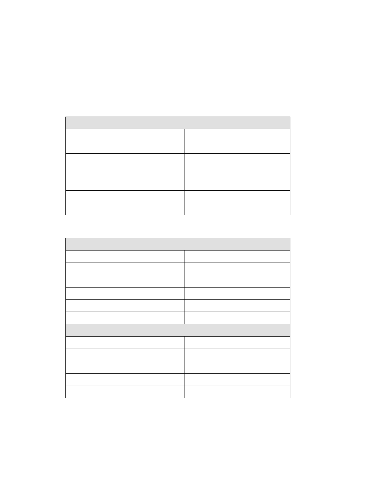
1.2.2 Interface Parameters
Signal input channel
DRGB port
Digital
Connector type
DVI-D
Signal format
TMDS
Dot clock range
27MHz ~148.5MHz
Horizontal scanning frequency range
36.25KHz~67.5KHz
Vertical scanning frequency range
50Hz~60Hz
Resolution range
640×480~1920×1080
Color depth
24bit
Control port
Serial port control and control loop-in
Connector type:
DB9F
Serial port type:
RS232
Data format:
8 data bits, 1 stop bit, no check bit
Baud rate:
9600
Input signal amplitude:
±3V~±15V
Output signal amplitude:
>±4V
Control loop-out
Connector type:
DB9F
Serial port type:
RS232
Data format:
8 data bits, 1 stop bit, no check bit
Baud rate:
9600
Input signal amplitude:
±3V~±15V
Page 11
User Manual VTRON LCD Display Panel
- 6 -
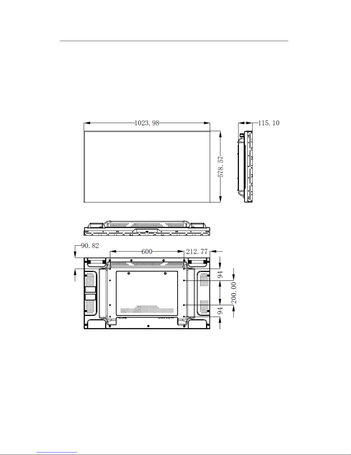
1.2.3 Product Outline Dimensions
Outline dimensions of L-PH4618 display panel:
Page 12

User Manual VTRON LCD Display Panel
- 7 -
Outline dimensions of L-PH4618 (L) display panel:
Page 13

User Manual VTRON LCD Display Panel
- 8 -
Outline dimensions of L-PH4628/L-PH4628 (L) display panel:
Page 14

User Manual VTRON LCD Display Panel
- 9 -
Outline dimensions of L-PH5518 (L) display panel:
Page 15

User Manual VTRON LCD Display Panel
- 10 -
Outline dimensions of L-PH5528/L-PH5528 (L) display panel:
Page 16

User Manual VTRON LCD Display Panel
- 11 -
1.3 Interface Overview
SN
Name
1
Power input port
2
ON/OFF button
3
RS232 in/out port
4
USB ports
5
HDMI port
6
DVI port
7
VGA port
8
PC audio port (currently unavailable)
9
Video input ports
10
Video output ports(currently unavailable)
11
Audio output ports
12
YPbPr ports
13
SV-Y/C input ports
14
Audio input ports
Note:
Please use the cable provided by VTRON. Otherwise, the signal quality may be
affected.
Page 17

User Manual VTRON LCD Display Panel
- 12 -
2. Remote Control
Precautions for remote control
The remote control shall be pointed directly to the receiving window. Any object
between the remote control and the receiving window may affect the normal
operation of the remote control.
The remote control shall be protected from any vibrant shake. The remote control
shall not be set or placed under direct sunshine. Otherwise, the heat may deform
the remote control.
The remote control may malfunction when the receiving window of the host is
under direct sunshine or strong light. In this case, please change the lighting angle
or the panel angle, or operate the remote control closer to the receiving window.
The remote control distance may be affected in case of insufficient battery voltage.
In this case, please replace with new batteries. If the remote control is idle for a
long time or the battery is used up, please remove the battery. Otherwise, the
battery leakage may erode the remote control, making it unusable.
Do not use batteries of different types. Do not use new batteries together with old
ones. Be sure to replace batteries in pairs.
Do not throw batteries into fire, recharge or decompose them. Please dispose of
the batteries according to the relevant environment protection regulations.
Page 18

User Manual VTRON LCD Display Panel
- 13 -
Key name
Function description
Standby
The key for switching between
normal state and standby state
Mute
The key used to enable/disable
sound function
Number keys
0~9
The number entry key
F1
The key used to
freeze/defreeze the image
Sound mode
The key used to switch sound
modes
Picture mode
The key used to switch picture
modes
Arrow key
Up/down: select function
Left/right: adjust the value of
the menu item
OK
The confirmation operation
Key
Volume +/-
The key used to
increase/decrease volume
Menu
The key used to display main
menu and return to the upper
level menu
Source
The key used to display signal
source selection menu
Display
The key used to display/cancel
the display panel’s address
number
Time set
The key used to shut down the
display panel at preset time
Zoom
The key used to switch the
display modes
Color
temperature
The color temperature
switching key
Play
Operation in USB mode (not
used)
Pause
Page 19

User Manual VTRON LCD Display Panel
- 14 -
Stop
Rotate
Previous
Next
Reverse
Forward
Battery installation method for remote control:
Remove the battery box cover, install two AAA (1.5V each) cells, ensuring that the
battery polarity is consistent with the polarity marks (+ and -) inside the battery box.
Note: The appearance of the remote control may be different from the figure. Please
refer to the actual product.
Page 20

User Manual VTRON LCD Display Panel
- 15 -
3. OSD Menu Operation
Signal source selection
Press the “Source” key on the remote control, and the “input signal source” menu
will be displayed on the screen. Press the “ ” and “ ” key on the remote
control to select the signal source, such as Video 1, Video 2, Video 3, Video 4,
S-terminal, component, PC, HDMI and DVI. Press the “OK” key on the remote
control or the “MENU” key on the panel, and then the display panel will switch to
the input signal source you have selected.
Table 3-1 Description of Signal Source Menu
Key name
Corresponding
input port
Description
Video 1
AV-1
Video channel 1,
loop-in channel
Video 2
AV-2
Video channel 2
Video 3
AV-3
Video channel 3
Video 4
AV-4
Video channel 4
S-terminal
SV-Y,SV-C
S-VIDEO channel
Component
Y,Pb,Pr
YPbPr channel
PC
VGA
VGA channel
HDMI
HDMI
HDMI channel
DVI
DVI
DVI channel
Main menu
Press the “Menu” key on the remote control or the “MENU” key on the panel, the
main menu will be displayed on the screen.
Page 21

User Manual VTRON LCD Display Panel
- 16 -
Picture menu
Select to display the picture menu.
Fig.3-1 Picture Menu
Special hint:
1) The hue function is available for NTSC signal only.
2) The contrast, brightness, saturation, hue and sharpness you adjust will be
automatically saved as the user mode.
Short-cut keys of the remote control
Picture mode: By pressing the “Picture mode” key on the remote control, you
can switch quickly among the following 4 modes: standard, soft, user, and
bright.
Table 3-2 Function Description of Picture Menu
Option
Function
Description
Picture mode
Adjust the overall display effect
of the picture
4 modes: standard, soft, user, bright
Contrast
Adjust the picture contrast
Setting range: 0-100
Brightness
Adjust the picture brightness
Setting range: 0-100
Page 22

User Manual VTRON LCD Display Panel
- 17 -
Saturation
Adjust the picture saturation
Setting range: 0-100
Hue
Adjust the picture hue
Setting range: 0-100
Sharpness
Adjust the picture sharpness
Setting range: 0-100
Aspect ratio
Adjust the image display aspect
ratio
Including full, 4:3, caption, movie
and PC modes
Color Temp.
Adjust the picture color
temperature
3 modes: Standard, warm, cool
Noise
reduction
Set the noise reduction class
4 classes: high, medium, low, OFF
Sound menu
Select to enter the sound menu.
Fig.3-2 Sound Menu
Special hint:
1) Please set the balance as 0 in normal situations.
2) The treble and brass analog values you adjust will be automatically saved
as custom mode.
Short-cut keys of the remote control
Sound mode: By pressing the “Sound mode” key on the remote control, you
can switch quickly between the following 4 modes: standard, music, movie,
and user.
Page 23

User Manual VTRON LCD Display Panel
- 18 -
Mute: the key to enable/disable sound.
Volume +/-: You can press the “Volume +/-” key on the remote control to
adjust the volume.
Table 3-3 Function Description of Sound Menu
Option
Function
Description
Sound mode
Select the sound effect mode
4 modes: standard, music, movie and user
Treble
Adjust the treble
Setting range: 0-100
Bass
Adjust the bass
Setting range: 0-100
Balance
Adjust the balance of the left
and right tracks
Setting range: -50-50
Auto volume
Adjust the volume
automatically
When it is ON, the system will automatically
adjust the volume.
Function menu
Select to display the function menu.
Fig.3-3 Function Menu
Page 24

User Manual VTRON LCD Display Panel
- 19 -
Table 3-4 Function Description of Function Menu
Option
Function
Description
OSD language
Set OSD language
Chinese and English are available
OSD duration
Adjust the OSD duration
4 options: 15s, 30s, 45s and 60s
OSD transparency
Adjust the OSD transparency
Setting range: 0-100
Blue screen
Set whether blue screen shall be
adopted when there is no signal
2 modes: ON, OFF
Sleep time
Set the duration before standby
“OFF, 15, 30, 45, 60, 90, 120, 240”,
unit: minute
Recall
Restore default setting
/
PC menu
Select to display the PC menu, which is available for PC signal source only.
Fig.3-3 PC Menu
Page 25

User Manual VTRON LCD Display Panel
- 20 -
Table 3-5 Function Description of PC Menu
Option
Function
Description
Auto Adjust
Automatically adjust the picture display effect
/
H-Position
Horizontal position adjustment
Setting range: 0-100
V-Position
Vertical position adjustment
Setting range: 0-100
Clock
Adjust the picture sampling clock frequency
Setting range: 0-100
Phase
Adjust the sampling clock phase
Setting range: 0-100
Page 26

User Manual VTRON LCD Display Panel
- 21 -
4. Connection Diagram for Display Panel (2×2)
Page 27

User Manual VTRON LCD Display Panel
- 22 -
5. Loop Connection Diagram
The signal will be input from the loop connection input interface and the output
through the loop connection output interface to the downstream display panel.
Page 28

User Manual VTRON LCD Display Panel
- 23 -
6. Installation of Display Panel
Precautions
In practical applications, generally several LCD display panels are combined into
an M×N array, which will become a LCD display wall with ultrahigh resolution.
Various factors should be taken into consideration during the installation. So
before the installation, the preparatory survey, scheme design work and others
should be performed. All installation operation should be done by qualified
engineers of VTRON or its agents. For more information about installation of
LCD display panels on site, please consult VTRON engineers.
The M×N LCD display wall system is composed of front display panels, mounting
racks and other devices.
Note: For installation details, please refer to the installation instructions.
Page 29

User Manual VTRON LCD Display Panel
- 24 -
7. Use of Display Panel
Use Instructions
If the display panel gives out any unusual noise, smoke or smell, plug off the
power connector immediately, and turn to the qualified technician for help.
Plug off the power connector in case of thunder storm or when the display panel
will be idle for a long time.
Check the power cable regularly to see if its insulation is intact and the contact
gets overheated.
In the following situations, please plug off the power connector and turn to the
qualified technicians:
The power connector or power cable is damaged or worn out;
Liquid drops into the display panel;
The display panel falls down to the floor or the enclosure is damaged;
The display panel has obvious functional exception or performance change;
The LCD is a fragile product made of glass. Any falling, striking or strong
vibration will cause the breakage of the glass. It is prohibited to forcefully press
the display zone of the LCD, or squeeze the LCD screen and frame during the
installation. You should pay attention to the overall evenness of the LCD and
avoid any bending or distortion caused by external force. Do not scratch the
display zone with hard objects.
The LCD may become crystallized when operating or stored in the temperature
and humidity range below the specifications, and this damage is unrecoverable. If
it is operated or stored in the temperature and humidity range above the
specifications, the crystal may turn into the isotropous liquid, and this damage is
also unrecoverable. Please store and use this display panel within the allowable
temperature and humidity range.
Page 30

User Manual VTRON LCD Display Panel
- 25 -
Avoid exposing the LCD module to direct sunshine or UV radiation.
The operating environment shall meet the following conditions: At least 100mm
clearance shall be maintained above, below and in front of the combined LCD
display wall. It is recommended that a clearance of more than 200mm shall be
reserved, so that the air around the display wall can be circulated effectively. The
display wall shall be kept away from the heat source.
Page 31

User Manual VTRON LCD Display Panel
- 26 -
7.1 System Startup/Shutdown
Startup sequence:
1. Check if the main power supply for the whole display wall system is ON.
2. Check if the power switch on the LCD display panel back plate is ON.
3. Start the control PC and run the control software (if the system requires the use
of the control software).
4. Start all the display panels via the control software or by pressing the system
switch on the interface board.
Shutdown:
Shut down all the display panels via the control software interface or by pressing
the system switch on the interface board.
Note:
When you select to shut down the display panel in the control software interface,
this operation only switches the display panel to standby state, and the power
supply of the display panel has not been shut down. You need to use the power
switch on the rear panel to completely shut down the power supply of the display
panel. When the display panels are in standby state, you can start all the display
panels again in the control software interface.
Page 32

User Manual VTRON LCD Display Panel
- 27 -
7.2 Display Signal Source
You can operate and manage all the input signal source contents through
professional control software, and display these signal source contents on the LCD
display panel.
For more information about control software configured onsite and its operation
instructions, please consult the system/equipment administrator.
8. Daily Maintenance
Precautions for maintenance
There is high voltage inside the equipment. The chassis shall be opened by the
specialized technician only.
This product is a precise device, and you are not allowed to open, disassemble or
modify on your own. Otherwise, the LCD or other internal components may be
damaged, making the equipment unusable.
The LCD surface shall be kept clean during the use and storage. If any water drip
is retained on the LCD, it will result in discolor or stain of the LCD. When there is
any stain on the LCD, wipe it off with cotton or soft cloth. It is prohibited to use
gasoline, alcohol or other chemicals to clean the screen.
If the screen is damaged and the liquid crystal drops onto your hands or clothes,
wash it with soap and clean water.
Do not press the screen surface of the LCD display panel forcefully.
Page 33

User Manual VTRON LCD Display Panel
- 28 -
Routine Inspection
Check if the system is properly grounded every month.
Check if the connecting wire and power cable are broken or worn out, if the
connector and plug-ins are loose, eroded and oxidized every month.
If the system is not frequently used, turn on and run it for 1 to 2 hours each
week. In damp seasons, the frequency shall be above once or more a day.
Page 34

User Manual VTRON LCD Display Panel
- 29 -
9. Contact us
About after sales service matters please contact after sales department of VTRON
GROUP CO.,LTD.
VTRON GROUP CO.,LTD.
No. 233 Kezhu Road, Guangzhou Hi-Tech Industrial Development Zone
(Guangzhou Science City),
Guangzhou 510670, China
Tel: +86-20-8390-8888
Fax: +86-20-8390-3591
Email: INFO@VTRON.COM
VTRON GROUP CO.,LTD. (Hong Kong)
Unit 1608-09, 16/F, Tower 1, 193 Prince Edward Road West, Grand Century
Place Mongkok, Kowloon Hong Kong
Tel: +852-2264-3688
Fax: +852-2264-3833
Email: INFO@VTRON.COM
VTRON Hong Kong Technical Support Centre
Unit 1225, 12/F, Corporation Park,11 On Lai Street,
Shatin, New Territories, Hong Kong
Tel: +852-2613-9708
Fax: +852-2613-9277
Email: INFO@VTRON.COM
VTRON GROUP CO.,LTD. (Malaysia Rep Office)
Unit 29-6 Block E1, Dataran Prima Business Centre, Jalan PJU 1/42, Petaling Jaya
47301, Selangor Darul Ehsan, Malaysia.
Tel: +603-7880-0338
Fax: +603-7887-0304
 Loading...