

Page 1
Page 2
User Manual Digicom Ark5000 Series Multi-screen Processor
i
This manual is copyrighted by VTRON with all rights reserved. Without written permission from VTRON, no
part of this document should be copied or transmitted in any forms or by any means.
This manual is used for operation instruction only and shall not be used for maintenance services. This manual is
subject to changes without notice.
This product may allow you to use third party software or upload, download the third party works, including
articles, images, video or software, but VTRON does not provide or own such third party works. Your use of the
above-mentioned third party works means that you agree to use such works without infringing or breaching he
rights of the third party works holders, and VTRON does not assume any liability for your use.
VTRON and Digicom are the registered trademarks of VTRON. All other brands and names mentioned in this
document are the property of their respective owners.
Note:
This manual is designed for the introduction to the Digicom Ark multi-screen
processor developed by VTRON. The specific configurations and functions shall be
in accordance with the purchase contracts signed with the customer. The functions
and display interface of the product you order might differ from those mentioned in
this manual. The reason may be there are differences between the one you purchased
and the one introduced in this manual.
Page 3
User Manual Digicom Ark5000 Series Multi-screen Processor
ii
Meaning of Symbols
■ Safety Instructions
The following symbols are used in this manual and on the equipment, indicating the potential injuries to the user
or other people and the risks of property damage, so that you can use the equipment safely and correctly. The
instructions and their corresponding meanings are listed as the following. Please make sure that you can
understand the indications correctly before reading this manual.
The product is a Class A product which may cause
radio interferences in the living environment. In such
case, it may be necessary to take practical measures
against the interferences.
The uninsulated hazardous voltage within the
equipment may result in electric shock.
CE approval indicates that the product has met
the safety requirements provided in EU
directives and the user can rest assured when
using the product.
CAUTION: In order to avoid electric shock, do not
open the cover and not place any objects in the
cabinet.
Page 4

User Manual Digicom Ark5000 Series Multi-screen Processor
iii
Important Instruction
Warning
To ensure the personal safety and the reliable operation of the equipment, please observe the following
instructions during the installation, operation and maintenance.
Precautions for Installation
◆ Do not use this product in the following places: any places with dust, oily fume, conductive dust, corrosive
gas and combustible gas; any places exposed to high temperature, condensation, wind and rain; any places with
vibration or shock. Electric shock, fire or incorrect operation may also lead to product damage and degradation.
◆ When perform screw hole machining and wiring, prevent metal debris and cut wires from falling into the
ventilation openings on the controller, as this may lead to fire, malfunction or incorrect operation.
◆ After the installation, do not block the ventilation openings with other objects, including any packing
material such as dustproof paper, otherwise poor heat dissipation may occur during the operation, which may
result in fire, malfunction or incorrect operation.
◆ Please avoid wiring, plugging or unplugging when the equipment is powered on, otherwise electric shock
circuit damage may occur.
◆ All installation and wirings must be firm and reliable as poor contact may lead to malfunction.
◆ In scenario with serious interferences, shielded cables should be used for input or output of high-frequency
signals, so as to enhance the anti-interference performance of the system.
Precautions for Wiring
◆ No installation or wiring operation should be performed until all external power supplies are disconnected,
otherwise electric shock or equipment may occur.
◆ This product is grounded through the ground conductor of the power cord. To avoid electric shock, the ground
conductor must be connected to the ground. Before connecting the input end and output end of this product, please
Page 5

User Manual Digicom Ark5000 Series Multi-screen Processor
iv
ground this product correctly.
◆ After completing installation and wiring, please remove the foreign objects immediately. Before connecting
the power supply, please close the terminal cover on the product to avoid electric shock.
Precautions for Operation and Maintenance
◆ When the power supply is connected, do not touch the terminal, otherwise, electric shock or incorrect
operation may occur.
◆ Please clean and tighten the terminal after the power supply is disconnected, as electric shock may occur
when such operations are performed when power supply is connected.
◆ Please perform the operations such as the connection or removal of communication signal cables or
extension module or control unit cables after the power supply is disconnected. Otherwise, equipment damage or
incorrect operation may occur.
◆ Do not disassemble the equipment lest the internal electric components may be damaged.
◆ Please read the manual carefully and fully confirm the safety before performing any program variation,
commissioning, starting or stopping operation.
Precautions for Product Abandonment
◆ During combustion, the electrolytic capacitor on PCB may explode.
◆ Please collect and dispose separately and do not mix with domestic garbage.
◆ Please dispose as industrial waste or according to the local provisions on environmental protection.
Page 6

User Manual Digicom Ark5000 Series Multi-screen Processor
v
Contents
Chapter1 Overview ........................................................................................................................ 1
1.1 Main Features ...................................................................................................................................... 2
1.2 Topological Diagram of the Processor System .................................................................................. 3
Chapter2 EP Cascade Processor ................................................................................................... 4
Chapter3 Ark5000 Overview ........................................................................................................ 5
2.1 Front Panel ........................................................................................................................................... 5
2.2 Rear Panel ............................................................................................................................................ 7
Chapter4 Technical Specifications .............................................................................................. 11
Chapter5 Installation ................................................................................................................... 13
5.1 Installation Environment .................................................................................................................. 14
5.2 Installation .......................................................................................................................................... 15
5.3 Connection with Peripherals ............................................................................................................ 18
Chapter6 VWAS ........................................................................................................................... 25
Chapter7 Daily Maintenance ...................................................................................................... 26
71 Daily Inspection and Maintenance ............................................................................................. 27
7.2 Routine Inspection ........................................................................................................................ 27
Chapter8 Troubleshooting ........................................................................................................... 28
Chapter9 Contact Us .................................................................................................................... 30
Page 7
User Manual Digicom Ark5000 Multi-screen Processor
1
Chapter1 Overview
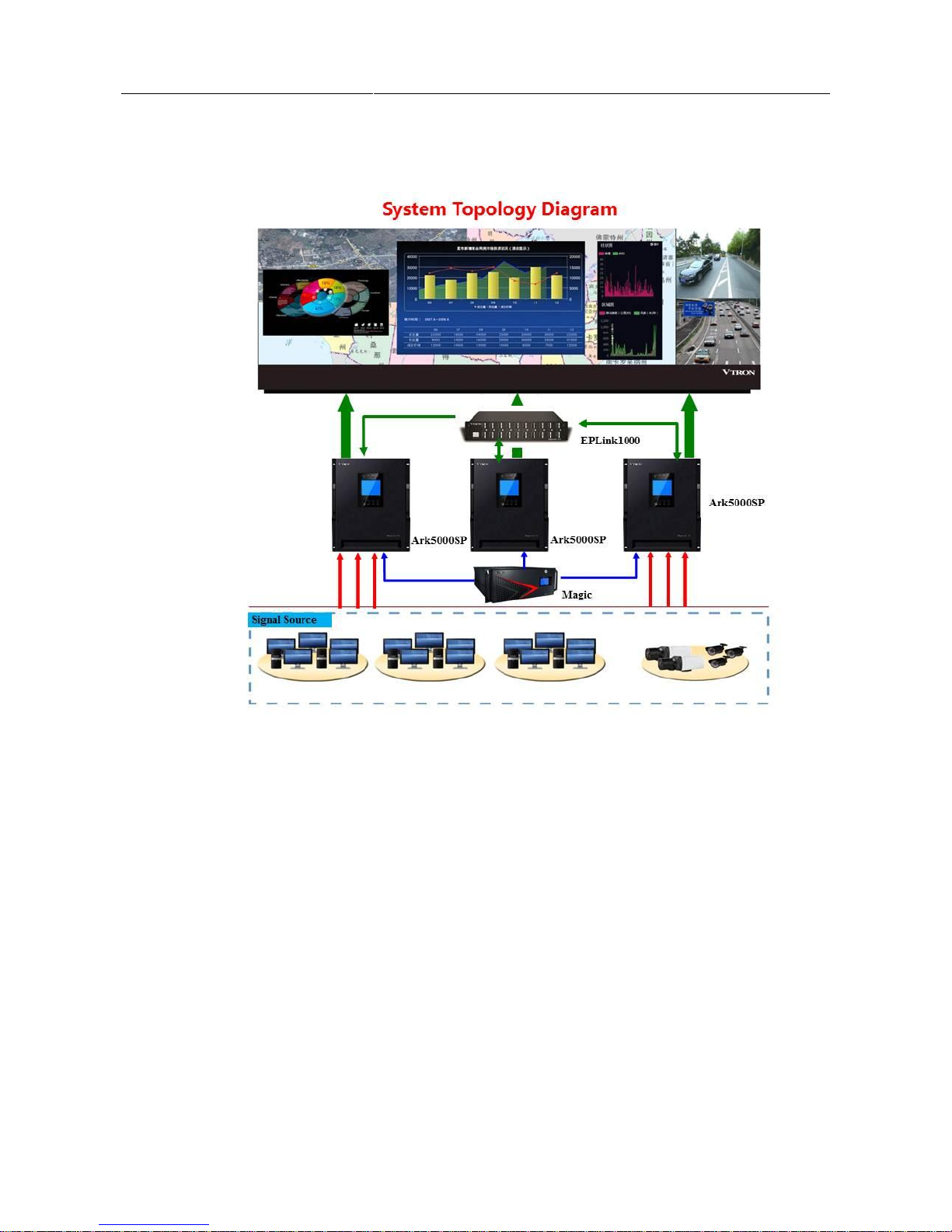
The Digicom Ark5000 multi-screen processor is a brand new high quality processor developed by VTRON.
Ark5000 adopts hardware-based architecture, featuring an advanced modular design, ultra-wideband digital signal
stream transmission technology, and real-time intelligent exchange transmission (RIET) technology, which allows
it to realize true, real-time signal display. With its hot redundant power supplies and the instant automatic
recovery capacity of the hot swappable key boards, the system can run stably, reliably, and flexibly. Ark5000
provides a solution for control rooms, command centers, operation maintenance centers, digital monitoring centers,
and meeting rooms.
Page 8

User Manual Digicom Ark5000 Multi-screen Processor
2
1.1 Main Features
Ultra-high speed bus, real-time display
Thanks to ultra-wideband digital signal stream transmission technology, the Digicom Ark5000 is able to realize
unparalleled display speed.
Hardware-based embedded architecture
The Ark5000 system utilizes an advanced hardware-based embedded architecture as well as real-time intelligent
exchange transmission (RIET) technology. It is a high-quality multi-screen processor featuring super high display
performance and unparalleled display speed. It can fulfill all demanding 7*24 visualization needs of the control
rooms, dispatch centers, and monitoring centers.
Powerful signal processing and expansion capacity
The 112-screen digital display wall system supports the real-time 144 DP inputs, 288 DVI inputs, 144 VGA
inputs, 288 HDMI inputs, 288 SDI inputs, 576 IP inputs, or 1152 VIDEO inputs. A single screen can support up
to 64 images display. The opened signal windows can be moved, superimposed, zoomed, or displayed across the
screen on any position on the wall. No matrix is needed, and the costs can be substantially reduced.
Modular design, easy maintenance
The modular design ensures that all the signal processing boards support hot-swapping and instant automatic
recovery(MTTR≦30seconds). The system power and fans feature a hot redundant design and support hotswapping. All the signal input/output boards support hot-swapping and fast maintenance. The system is easy to
maintain.
Intelligent system management
The system air inlets/outlets and core components feature an intelligent temperature control, real-time monitoring,
a high-temperature alarm, real time status information check, system operating status visual monitoring through
LCD display panel.
Page 9
User Manual Digicom Ark5000 Multi-screen Processor
3
1.2 Topological Diagram of the Processor System
Page 10
User Manual Digicom Ark5000 Multi-screen Processor
4
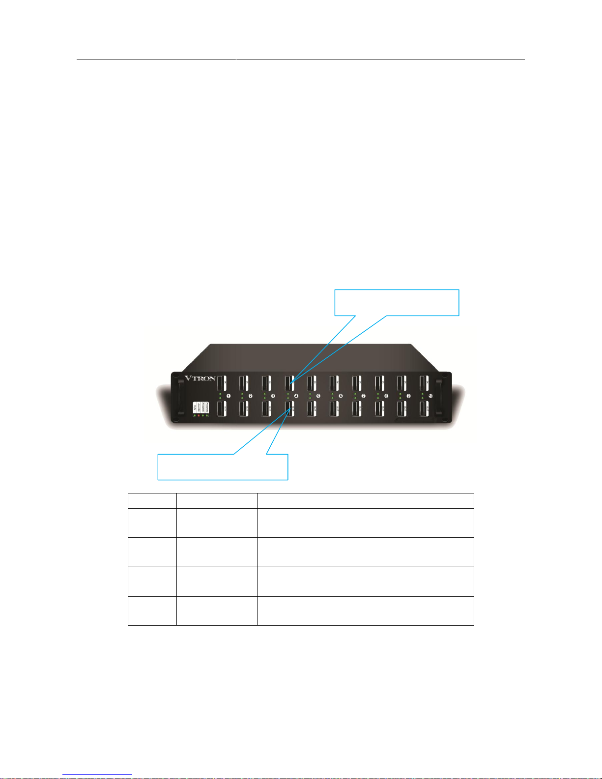
Chapter2 EP Cascade Processor
The EP cascade processor has the following features.
1) A 10-channel Digicom Ark 3300EP supports up to 10 groups of extension, i.e. 10 signal processors
extension.
2) The signal extension processor takes 8-in and 8-out as one group of switching
3) The signals are extended with high speed signal transmission cable, which is up to 5m.
4) Signal processors allow interconnection and extension.
5) Support synchronization clock extension.
Indicator
Color
Function
RUN
Green
Working state indicator; flashes when the board works
normally and is exchanging data.
ALARM
Red
Working state indicator; flashes when the board works
abnormally.
POWER1
Green
Working state indicator; constantly on when POWER1 works
normally
POWER2
Green
Working state indicator; constantly on when POWER2 works
normally
Cascade signal output port
Cascade signal input port
Page 11
User Manual Digicom Ark5000 Multi-screen Processor
5
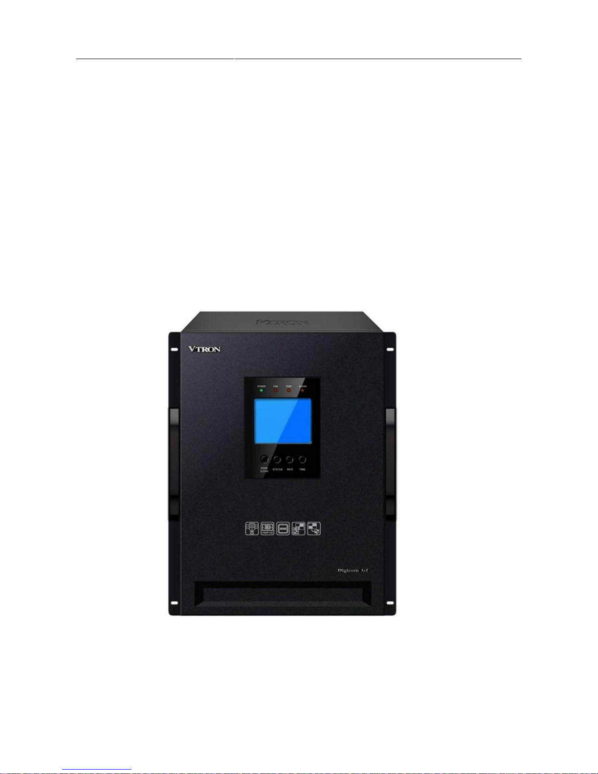
Chapter3 Ark5000 Overview
The following front and rear panels are for reference only. In actual use, the appearance of the panels may be
different from those introduced in this manual due to different order for the configuration.
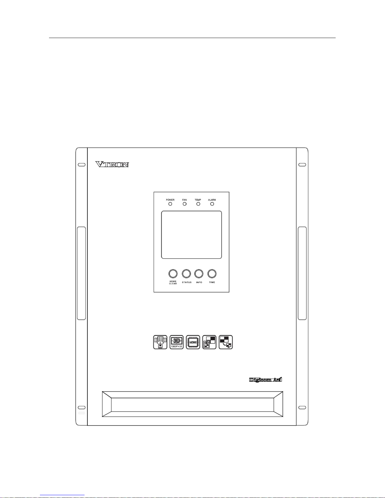
2.1 Front Panel
Page 12

User Manual Digicom Ark5000 Multi-screen Processor
6
① LED indicators
There are 4 LED indicators on the front panel, including POWER, FAN, TEMP and ALARM. All of them are
bi-color LEDs(red and green).
LED indicator
Function
Normal operation
Abnormal situation
POWER
Indicate the operating status of
the processor power
Green
-
FAN
Indicate the operating status of
the fan in the chassis
Green
Red
TEMP
Indicate the temperature
monitoring status in the chassis
Green
Red
ALARM
Indicate the alarm monitoring
status
Green
Red
② LCD display panel
The user can more clearly see the operating status of the hardware resources in the processor system through the
display information on the LCD panel.
③ Function keys
There are 4 function keys on the front panel, including HOME CLEAR, STATUS, INFO, and TIME.
key
Function
HOME
CLEAR
Turn to the home page
Clear the system alarm(hold for 2 seconds)
STATUS
Display the system status
INFO
Display the IP address of the main control board
TIME
Display system time
Page 13

User Manual Digicom Ark5000 Multi-screen Processor
7
2.2 Rear Panel
Interfaces on rear panel include signal input and output ports, system power switch, power input ports, and chassis
grounding screw. The interfaces mentioned above are all in the respective boards. The following description
shows you the details of the interfaces and the boards. The rear panel is shown in the following figure.
Note:
The quantity and the slot that the board placed may vary due to the different configuration requirement of the
contract.
Page 14

User Manual Digicom Ark5000 Multi-screen Processor
8
① Slot 1 and slot 2—HDMI signal input board
Interface: 4 HDMI inputs/board
The board has operating status indicator and alarm indicator functions.
Page 15

User Manual Digicom Ark5000 Multi-screen Processor
9
② Slot 3 and slot 4—HDMI 4K signal input board
Interface: 2 HDMI inputs/board
The board has operating status indicator and alarm indicator functions.
③ Slot 5 and slot 6—DVI signal input board
Interface: 4 DVI-D inputs/board
The board has operating status indicator and alarm indicator functions.
④ Slot 7 and slot 8—VGA signal input board
Interface: 4 VGA inputs/board; supported signal formats: RGBHV, RGBS, RGsB, and etc.
The board has operating status indicator and alarm indicator functions.
⑤ Slot 9 and slot 10—SDI signal input board
Interface: 4 SDI inputs/board
The board has operating status indicator and alarm indicator functions.
⑥ Slot 11 and slot 12—VIDEO(CVBS) signal input board
Interface: 4 BNC inputs/board; supported signal formats: PAL, NTSC, and etc.
The board has operating status indicator and alarm indicator functions.
⑦ Slot 13 and slot 14—IP signal input board
Interface: 2 RJ45 inputs/board
The board has operating status indicator and alarm indicator functions.
⑧ Slot 15 and slot 16—VIDEO (CVBS) signal input board
Interface: 16 BNC inputs/board, supported signal formats: PAL, NTSC, and etc.
The board has operating status indicator and alarm indicator functions.
⑨ Slot 17~slot 20 DP desktop input board
Interface type: 2 DP inputs/board
The board has operating status indicator and alarm indicator functions.
Note: Both signal input board and desktop input board can be placed at the slot17 and slot18.
⑩ Slot 21 and slot 22—Cascade signal output board
Interface type: 3 PCI-E cascade ports /board
The board has operating status indicator and alarm indicator functions.
Page 16

User Manual Digicom Ark5000 Multi-screen Processor
10
⑪ Slot 23—Audio signal output board
Interface type: 8 RCA ports /board
The board has operating status indicator and alarm indicator functions.
⑫ Slot 24—4K signal output board
Interface type: 2 XFP ports /board
The board has operating status indicator and alarm indicator functions.
⑬ Slot 25~36—DVI output board
Interface type: 2 DVI-D outputs/board, supporting 32-channel signal output and up to 4-wall display. A
single screen can support up to 64 images display.
⑭ Slot 37—Preview output board
Interface type: 2 DVI-D outputs/board, Ethernet port.
The board has operating status indicator and alarm indicator functions.
⑮ Slot 38 and 39—Live view board
Interface type: 2 DVI-D outputs/board, Ethernet port.
The board has operating status indicator and alarm indicator functions.
⑯ Slot 40—System control board
Interfaces contained in the system control board: dial switch, RS232 debug interface, RS232 control port,
Ethernet port, sync in/out BNC ports, and etc.
Page 17

User Manual Digicom Ark5000 Series Multi-screen Processor
11
Chapter4 Technical Specifications
Digicom Ark5000 multi-screen processor
DVI output
(Expandable)
Number of outputs: Up to 36
Output resolution: 1024×768@60Hz~1920×1080@60Hz
2.5GB DDR3 graphic memory
Color depth: 24 bits
Output interface: DVI-D
Audio output
Number of outputs: Up to 8
Output resolution: Up to 192KHz
Dual-audio output supported
Output interface: RCA 3.5mm
4K output
Number of outputs: Up to 16
Output resolution: 1024×768@60Hz~3840×2160@30Hz
2.5GB DDR3 graphic memory
Color depth: 32 bits
Output interface: XFP
Cascade
Number of signal cascade ( a single cascade board): Up to 8
Output interface: PCI-E cascade port
DVI input
(Expandable)
Number of inputs: Up to 72
Input resolution: 640×480@60Hz~1920×1200@60Hz
Color depth: 24 bits
Input interface: DVI-D
VGA input
(Expandable)
Number of inputs: Up to 72
Input resolution: 640×480@60Hz~1920×1200@60Hz
Color depth: 24 bits
Input interface: VGA
Video input
(Expandable)
Number of inputs: Up to 288
Support CVBS signal in PAL/NTSC signal system
Input interface: BNC
IP input
(Expandable)
Number of inputs: Up to 36 channels of 1080P@60Hz, 144 channels of 1080P@30Hz, or 144
channels of D1
Input resolution: D1, 720P, 1080i, 1080P
Input interface: RJ45
HDMI input
(Expandable)
Number of inputs: up to 72
Input resolution: 720×480@60Hz~1920×1080@60Hz
Input interface: HDMI
HDMI 4K input
(Expandable)
Number of inputs: Up to 36 channels of 4K2K signal
Input resolution: 480/576i, 480/576P, 720P, 1080i, 1080P, 2160P
Input interface: HDMI
Page 18

User Manual Digicom Ark5000 Series Multi-screen Processor
12
DP Input
(Expandable)
Number of inputs: Up to 36 channels of 4K2K signal
Input Resolution: 800×600@60Hz~3840×2400@30Hz
Input interface: DP
Preview output
(Expandable)
Number of outputs: Up to 16
Output resolution:
DVI port:1920×1080@60Hz; Ethernet port: 1920×1080@30Hz
Output interface: DVI-D and RJ45
Live view
(Expandable)
Number of outputs: 1 wall live view
Output resolution:
DVI port: 1920×1080@60Hz; Ethernet port: 1920×1080@30Hz
Output interface: DVI-D and RJ45
SDI input
(Expandable)
Number of inputs: Up to 72
Input resolution: SD-SDI, HD-SDI, 3G-SDI
Input interface: SDI
Hot swappable
board
The signal board supports hot swapping and instant automatic recovery. The time for recovery is
≤30 seconds.
System fan
Hot redundant fan, supporting hot swapping.
Power supply
N+1 hot redundant power supplies, N≤3
100-240V AC 50/60Hz 10-5A
Power
consumption
≤900W
Chassis size
19" standard rack mounting, height of chassis: 12U, installation space: 16U
W × H ×D=482.4 mm × 577.6 mm × 629 mm(with handle)
W × H ×D=439.4 mm × 577.6mm ×589 mm(without handle)
System control
Dual 100MJ45 Ethernet interface, 10/100M self-adaptive
Supports the configuration of network applications, such as IP address, gateway, time server, etc.
Intelligent
management
Supports alarm monitoring for temperature, fan, power supply etc.
Supports version checking and online software upgrades
Processor
software
VTRON VWAS software (needs to be purchased separately)
Certification
CCC, CE, CB, RoHS
Note:
The number of the inputs and outputs is subject to the specific project. The actual product configuration and
performance depend on the user’s order. For more details, please contact VTRON or its distributor.
To maximize the hardware resources of the system, the user may need to purchase additional peripherals for
specific projects.
The specifications mentioned above are subject to change without prior notice
Page 19

User Manual Digicom Ark5000 Series Multi-screen Processor
13
Chapter5 Installation
Precautions for Installation
1) The onsite installation shall be performed by the trained and qualified technicians. Please turn to the
after-sales service or agent of VTRON for technical instruction before installation. For safety, at least
two technicians are needed to perform the installation onsite.
2) When shipped from factory, the Ark5000 processor is provided to the user as a whole unit. All hardware
board modules and software program modules of Ark5000 processor are produced in the factory
according to the strict production procedures and have undergone a series of tests such as a high
temperature and aging tests.
3) Before installing the Digicom Ark5000 processor, please check whether the installation environment
meets the requirements of the operating environment (e.g. temperature, humidity, power supply,
grounding system, etc.), so as to ensure that the equipment can be put into normal operation after
installation, and its service can be guaranteed.
4) Please use the cables delivered together with the product (including the signal cable, network cable, and
power cable). If the user needs to use his/her own cable, please turn to the after-sales service department
or agent of VTRON for corresponding instructions.
Page 20

User Manual Digicom Ark5000 Series Multi-screen Processor
14
5.1 Installation Environment
Before installing the Ark5000 processor, please check whether the installation environment meets the
requirements of the operating environment (e.g. temperature, humidity, power supply, grounding system, etc.), so
as to ensure that the equipment can be put into normal operation after installation, and its service life can be
guaranteed.
Requirements on temperature and humidity
Operating temperature: 0ºC-40ºC
Relative humidity: 10%-90% (no condensation)
Requirements on power supply
The power supply for the Ark5000 shall be ~110-240V 50/60 Hz. Please make sure that such power supply can
be provided in the installation environment. In addition, to make sure the stability of the power supply to the
Ark5000 processor, the power plug of the processor must be connected to the independent power plug board.
(220V 10A standard plug board is recommended). Do not share power plug with other equipment.
Requirements on grounding
Therefore, when installing the Digicom Ark5000 processor, grounding measures of the whole system environment
need to be fully considered, including whether the power supply has the grounding measure (e.g. adopting the
certified three-core power cable and power socket). Corresponding equipment grounding terminals should be
reserved in the on-site system grounding. When there are insufficient grounding terminals in the system grounding,
it is necessary to increase the number of grounding terminals by increasing the number of grounding bar. (The
resistance between the on-site reserved system grounding terminals and the protection ground should be lower
than 3 ohms).
Besides, when installing the Digicom Ark5000 processor in the high-rise building, the equipment shall be
connected to the true earth through the dedicated safe grounding system and kept away from the lightning
protection system of the building. Improper system grounding will have large negative effect on the signal
transmission, which will result in the imaging interference that cannot be removed through debugging. For details,
please consult VTRON. Please strictly comply with the relevant instructions and maintain proper grounding
Page 21

User Manual Digicom Ark5000 Series Multi-screen Processor
15
during the use of the equipment.
5.2 Installation
When shipped from factory, the Ark5000 processor is provided to the user as a whole unit. For installation, all you
need is just to install the processor into the rack. The following description will show you the details about the
rack mounting.
Note: the installation rack is not provided with the processor, please purchase it for yourself. The racks should
meet standard of GB/T 3047.2-1992 or IEC 60297. The 800mm (width) × nU (height) × 1200mm (depth) one is
recommended. (“n” depends on the quantity of the devices you need to install). For further information, please
consult the VTRON after sale services.
The detailed installation steps are shown as below:
1. Install or adjust the plate to a suitable position according to the installation layout of the processor in the
cabinet.
2. Install the chassis and fasten it to the rack with screws. (Special screws for the cabinet must be used).
Page 22

User Manual Digicom Ark5000 Series Multi-screen Processor
16
3. Fix the cables connected to the rear side of the processor.
Page 23

User Manual Digicom Ark5000 Series Multi-screen Processor
17
Page 24

User Manual Digicom Ark5000 Series Multi-screen Processor
18
5.3 Connection with Peripherals
Connection with display equipment
Use the signal cable delivered with the product to connect the output interface of the Digicom Ark5000
multi-screen processor to the corresponding input interface of the display equipment or processor.
Note:
Digital signals have strict requirements on transmission. Therefore, the user is advised to use the signal
cable provided by VTRON. Please consult VTRON or agent before attempting to use other signal
cables.
Page 25

User Manual Digicom Ark5000 Series Multi-screen Processor
19
Connection with signal source
Connect the CVBS input channels on the Ark5000 processor to the output channel on the CVBS signal
sources with the CVBS video signal cables delivered with the product. Connect the VGA signal input
channels on the Ark5000 processor to the output channels on the DVI signal sources with the DVI signal
conversion cables delivered with the product.
The VGA signal source onsite generally refers to the PC, professional workstation, or the matrix connected
to such equipment. There are many types of video signal sources, including common video player
equipment and cameras. Since there are many video input channels, make sure to connect the correct
channel to the corresponding signal source. Only in this way can you correctly access the video signal
source in the applications.
The following description will just take the VGA signal input as an example. For connection of other signal
sources, they are all similar. So no more description will be provided.
Connection with network cable
The Ark5000 processor can be physically located in the network and can also be controlled through the
Page 26

User Manual Digicom Ark5000 Series Multi-screen Processor
20
network. Therefore, in actual application, the user needs to connect the Ark5000 processor with the network
through switching equipment, that is, to use network cables to connect the switching equipment with the
Ethernet interface. The Ethernet interfaces to be connected depend on the onsite network availability.
Page 27

User Manual Digicom Ark5000 Series Multi-screen Processor
21
Connection with power cord
The power socket of the Ark5000 processor is located at the bottom left corner of the rear panel of the equipment.
This is shown in the following figure.
Power input
Page 28

User Manual Digicom Ark5000 Series Multi-screen Processor
22
When connecting the equipment power socket and plug board, please use the cable delivered together with the
equipment. Incompliant power cable will affect the power supply, performance stability, and safety of the
equipment. In addition, to ensure the stability of the power supply to the Arkk5000 processor, the power socket of
Ark5000 must be connected to the independent power plug board. (The 220V10A standard plug board is
recommended). Do not share the power plug board with other equipment.
System grounding
The Digicom Ark5000 has 2 grounding points: the built-in grounding wire connecting point of the 3-core power
cable, and the enclosure grounding stud of the system. To ensure the safety and stability of the equipment as well
as the safety of the operator, the equipment must be properly and securely grounded. That is, the special three-core
cable delivered together with the equipment shall be used. Besides, the grounding screw at the right lower corner
of the chassis rear panel must be connected to the dedicated grounding system with dedicated grounding
conductor through proper method.
Page 29

User Manual Digicom Ark5000 Series Multi-screen Processor
23
System grounding
screw
Page 30

User Manual Digicom Ark5000 Series Multi-screen Processor
24
Note:
To ensure the safe operation and normal working of the system, the product must be grounded. Improper
grounding will severely affect the reliability and stability of the system and cause negative impact on the signal
quality. Therefore, when installing the Digicom Ark5000 processor, you need to fully consider the grounding
measures of the whole system environment, including whether the power supply has the grounding measure (e.g.,
adopting the certified three-core power cable and power socket). Besides, when installing the Digicom Ark5000
in the high-rise building, the equipment shall be connected to the true earth through the dedicated safe grounding
system and kept away from the SPD grounding system of the building. Improper system grounding will have
large negative effect on the signal transmission, which will result in the imaging interferences that cannot be
removed through debugging. For details, please consult VTRON. Please strictly comply with the relevant
instructions and maintain proper grounding during the use of the equipment.
Page 31

User Manual Digicom Ark5000 Series Multi-screen Processor
25
Chapter6 VWAS
VWAS(VTRON Display Wall Administration System)is the application system developed by VTRON for the
development, design, and the production of the display wall system and its multi-screen processing system. It is
mainly used to control and manage the hardware in the display wall system (e.g., the display unit, the multi-screen
processor, and other peripherals), so as to realize the management and control of the signal windows and
application windows shown on the display wall. The VWAS can make full use of network distributed software
systems and support simultaneous connections and the operation of several clients. It provides a simple, friendly,
and customized man-machine interface, allowing for quick and convenient control and simple operation using the
combined display wall and completely eliminating the shortcomings and traditional display walls, i.e. complex
operations.
For the detailed operation instructions of the VWAS software, please refer to the VWAS software user manual.
Page 32

User Manual Digicom Ark5000 Series Multi-screen Processor
26
Chapter7 Daily Maintenance
Please read carefully and strictly comply with the following safety
precautions before use and during daily maintenance and troubleshooting.
This is very important for your safety and for protecting your equipment. \
1. Do not open the top cover of the multi-screen processor. There are no user serviceable
parts in the chassis and the equipment does not need any internal adjustments.
2. To replace any components or repair the equipment, please contact the local authorized
service center. We are prepared to provide prompt service and help you solve the
relevant problems.
3. Daily maintenance and troubleshooting must be performed by trained and qualified
personnel.
4. Strictly follow the stipulated ON/OFF steps, and avoid noncompliant operation.
5. Before connecting or disconnecting any electrical plug/socket between the system
devices or making any other connections, please make sure the system has been shut
down and the system power cable has been unplugged.
6. Keep the equipment away from any corrosive chemical gases, agents, or inflammable,
explosive materials.
7. Do not add or change any of the equipment’s mechanical parts or electrical circuits. If
you do so, VTRON will assume no liability for the results thusly caused.
8. When replacing the equipment modules, be sure to take proper antistatic measures. For
example, wear antistatic clothes, antistatic shoes, antistatic helmet, or an antistatic wrist
strap. Hold the edge of boards carefully and avoid touching the components of the
boards when handling the boards.
9. Be sure to use the standard accessories provided by VTRON.
Safety Precautions
!
Page 33

User Manual Digicom Ark5000 Series Multi-screen Processor
27
71 Daily Inspection and Maintenance
(1) The operating environment of the equipment needs to be kept free of dust, be dry, and have good
ventilation.
(2) Operating temperature: 0 ºC - 40 ºC,
Relative humidity: 10% - 90%, no condensation.
(3) Keep the equipment clean, and avoid using any rough or abrasive cleaning agents.
(4) Do not place anything in or on top of the ventilation holes and ventilation slots. Avoid spraying any
liquid or chemicals on or near the equipment.
7.2 Routine Inspection
(1) Make sure the power supply is normal before startup.
(2) Make sure the system is properly grounded every month.
(3) Check to see if the connecting wire or power cable are broken or worn out, if the connectors or
plug-ins are loose, eroded, or oxidized every month.
(4) If the system is not frequently used, turn it on and run it for 1to 2 hours every week. In damp seasons,
the frequency of such operations should be more than once a day.
Page 34

User Manual Digicom Ark5000 Series Multi-screen Processor
28
Chapter8 Troubleshooting
Problem
Solution
The POWER indicator on the host does not
light up.
Make sure the power cord is correctly connected and the
power switch is turned on.
There is a warning sound from the system
beeper and the red indicator on the main control
board keeps flashing.
Make sure the fan is working properly and the system
temperature has not exceeded the acceptable range.
The control software cannot control the system.
Make sure the network cable between the control host and
the system main control board is properly connected and
the network indicator indicates normal status.
The red alarm indicator on the board keeps
flashing.
Make sure the board is in good contact with system
backboard and the operating temperature of the board does
not exceed the acceptable range.
There is no display on the display terminal, and
the multi-screen processor does not have any
alarm message.
Make sure the display terminal equipment has been started;
Check the connection status of the signal cable of
multi-screen processor;
Check to see if the board modules of the multi-screen
processor have been started normally.
Abnormal image color
Check the signal cable status of the multi-screen processor
or the system grounding status;
Check to see if the signal output equipment has signal
output problem.
Make sure the signal source parameters are properly set;
Check the display terminal (e.g., the display wall).
There are ripples, fluctuations, or color
derivations in the output image.
Make sure he corresponding signal cable is properly
connected.
Page 35

User Manual Digicom Ark5000 Series Multi-screen Processor
29
Make sure the power supply ground wire is in good
condition.
Obvious static electricity can be felt when
touching the metal parts of the host machine.
Make sure the grounding stud on the host machine is
properly grounded.
Page 36

User Manual Digicom Ark5000 Series Multi-screen Processor
30
Chapter9 Contact Us
About after sales service matters please contact after sales department of VTRON GROUP
CO.,LTD.
VTRON GROUP CO.,LTD.
No. 233 Kezhu Road, Guangzhou Hi-Tech Industrial Development Zone (Guangzhou Science
City),
Guangzhou 510670, China
Tel: +86-20-8390-8888
Fax: +86-20-8390-3591
Email: INFO@VTRON.COM
VTRON GROUP CO.,LTD. (Hong Kong)
Unit 1608-09, 16/F, Tower 1, 193 Prince Edward Road West, Grand Century Place Mongkok,
Kowloon Hong Kong
Tel: +852-2264-3688
Fax: +852-2264-3833
Email: INFO@VTRON.COM
VTRON Hong Kong Technical Support Centre
Unit 1225, 12/F, Corporation Park,11 On Lai Street,
Shatin, New Territories, Hong Kong
Tel: +852-2613-9708
Fax: +852-2613-9277
Email: INFO@VTRON.COM
VTRON GROUP CO.,LTD. (Malaysia Rep Office)
Unit 29-6 Block E1, Dataran Prima Business Centre, Jalan PJU 1/42, Petaling Jaya 47301,
Selangor Darul Ehsan, Malaysia.
Tel: +603-7880-0338
Fax: +603-7887-0304
 Loading...