

Page 1

User Manual
Digicom Ark 3100SP
Multi-screen Processor
V2.1
VTRON
http :// www.vtron.com
E-Mail: info@vtron.com
All rights reserved
Page 2
User Manual Digicom3100SP Multi-screen Processor
The copyright of this manual belongs to VTRON. Without written permission, the copy or
promulgation of any part of this manual in any means is prohibited.
The manual is subject to change without prior notice.
This product may allow you to use the third party’s software or upload, download the third party’s
works, including articles, images, video or software, but VTRON does not own or provide such
third party’s works. By using the above-mentioned third party’s works, you agree that you will use
such works without infringing or breaching the rights of the third party and VTRON will not
assume any liability for your use.
VTRON and Digicom are registered trademarks of VTRON. Windows, Windows NT, Windows
2000 and Windows XP are trademarks or registered trademarks of Microsoft Cooperation in USA
and/or other countries (regions). Other product names or company names in this manual may be
the trademarks of the owners respectively.
Notice
This manual is designed for Digicom Ark 3100SP Multi-screen Processor of VTRON. The specific
configuration and function depend on the order contract. If you find that certain functions and
interfaces of ordered products are different from the content of this manual, the ordered product may
be different from those described in this manual.
Statement
This is a Class A product, which may cause radio interference in living environment. In this case, the
user needs to take practical measures.
Page 3
User Manual Digicom3100SP Multi-screen Processor
Before operating VTRON Digicom Ark 3100SP Multi-screen Processor please read the
following carefully:
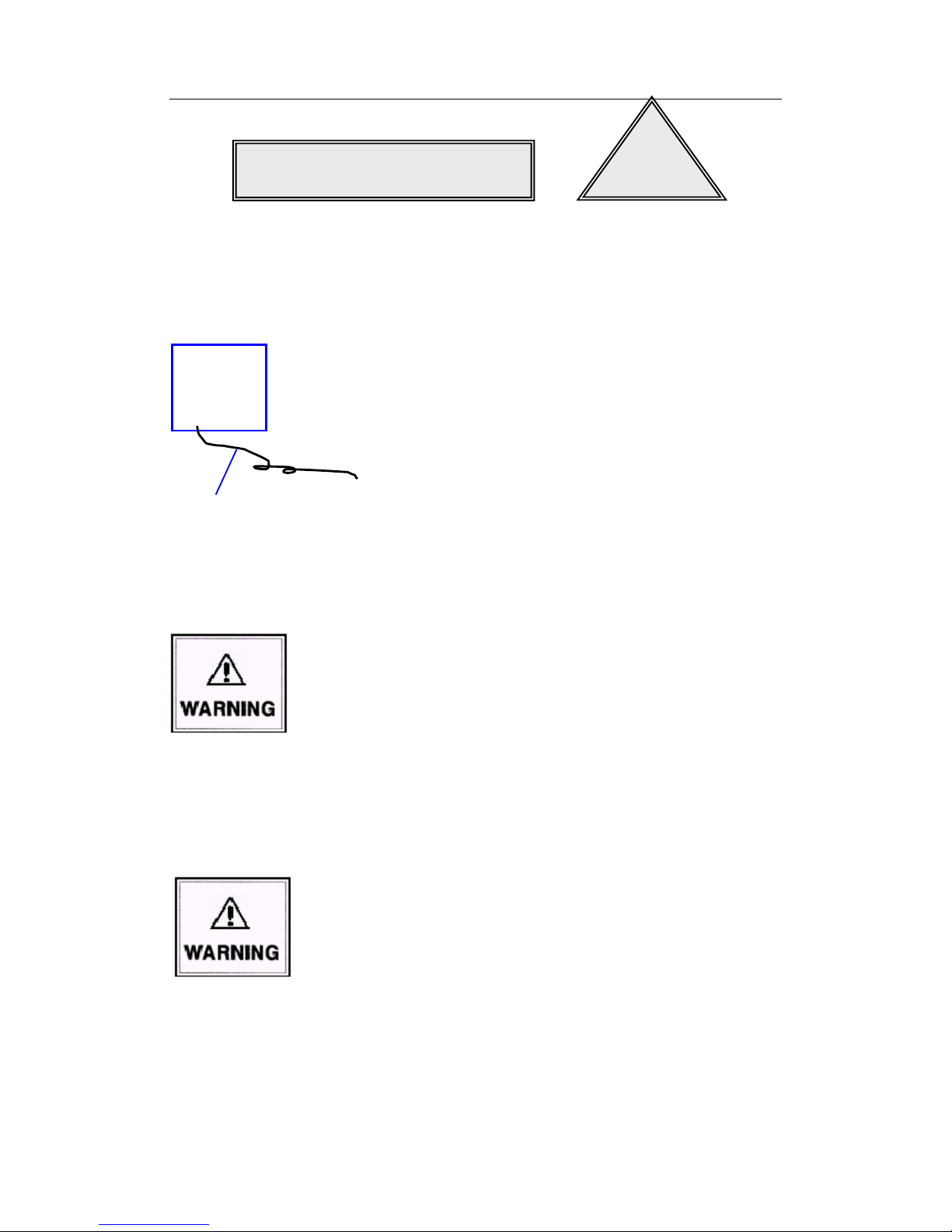
Perfect grounding measures (as in the left figure)
The product should be grounded properly. Otherwise, a series
of problems will occur: serious system fault, system
instability and unreliability, and even the paralysis to the
whole system. Even worse, the safety of users cannot be
ensured.
Do not change the original design
Do not add or delete any mechanical parts or electrical loop of
the product, or else VTRON isn’t responsible for any result
thereby.
Do not install illegal software
The Multi-screen signal processor described in this manual is
dedicated image processing and controlling device, and
shouldn’t be used for other purposes. If it is necessary to
install other software, please consult VTRON or designated
agent, or else VTRON isn’t responsible for any result thereby.
Safety Warning
!
Earth wire (connect
to earth)
●
Page 4
User Manual Digicom3100SP Multi-screen Processor
Away from corrosive chemicals, pharmaceuticals
The corrosive chemicals and pharmaceuticals will damage the
mechanical parts and electrical loop of the product and affect
the service life directly. Do not use highly volatile solvents or
detergents, such as gasoline, thinner and acetone, to clean the
interior and exterior of the product.
Away from flammable, explosive objects
The flammable and explosive objects are not only the threat to
the product, but also to the users’ safety.
Away from strong electromagnetic interference equipment
In the environment with strong electromagnetic interference,
the performance of the product can’t be exerted, and the
stability is also affected.
Be sure to cut off power supply
Please cut off the power supply before the following
operations:
A. Remove or reinstall any part (unless HOT SWAP
parts).
B. Disconnect or reconnect the electrical plug of any part
or any other connections.
Page 5
User Manual Digicom3100SP Multi-screen Processor
Disconnecting device of the power supply
This device uses appliance coupler or power plug as the
disconnecting device. Please make sure that the plug or
coupler is reachable, so as to disconnect the power supply
through the coupler or plug upon emergency.
Note
A. The device integrates replaceable batteries. It may cause
explosion if the battery model isn’t proper. Please
replace with the batteries provided by VTRON.
B. Follow the instructions to dispose the used batteries.
Please consult local environment protection department
for the treatment of used batteries.
Page 6

User Manual Digicom3100SP Multi-screen Processor
Contents
1. Introduction ........................................................................................................................................ 1
1.1 About Digicom Ark 3100SP Multi-screen Processor ..................................................................... 1
1.2 Functions and Features ................................................................................................................... 2
1.2.1 Digicom Ark 3100SP Multi-screen Processor ......................................................................... 2
1.2.2 Functions and Features of SPV3000 Signal Preview Processor (Optional) ............................ 6
1.2.3 Functions and Features of SMA3000 Streaming Media Processor (Optional) ........................ 7
1.3 Appearance ..................................................................................................................................... 9
1.3.1 Digicom Ark 3100SP Multi-screen Processor ......................................................................... 9
1.3.2 SPV3000 Signal Preview Processor(Optional) ................................................................ 15
1.3.3 SMA3000 Streaming Media Processor ................................................................................. 16
1.4 Technical Specifications ............................................................................................................... 18
1.5 Classical Application Diagram ..................................................................................................... 22
2. Introduction to Boards ..................................................................................................................... 23
2.1 System Main Control Board ......................................................................................................... 23
2.2 Signal Processing Board ............................................................................................................... 24
2.3 Audio Signal Expansion Processing Board .................................................................................. 25
2.4 RGB Signal Acquisition Board (Optional) ................................................................................... 26
2.5 Video Signal Acquisition Board (Optional) .................................................................................. 28
2.6 Dual-Link Signal Acquisition Board (Optional)........................................................................... 29
2.7 HDMI Signal Acquisition Board (Optional) ................................................................................ 30
2.8 DisplayPort Signal Acquisition Board (Optional) ........................................................................ 31
2.9 SDI Signal Acquisition Board(Optional) ................................................................................ 32
2.10 Optical Signal Acquisition Board (Optional) ............................................................................. 33
2.11 Optical Signal Output Board (Optional) ................................ ..................................................... 34
2.12 IP Streaming Signal Acquisition Board(Optional) ................................................................ 35
2.13 Desktop Processing Board (Optional) ........................................................................................ 36
2.14 Live View Board (Optional) ....................................................................................................... 38
Page 7

User Manual Digicom3100SP Multi-screen Processor
3. Installation ........................................................................................................................................ 39
3.2 Installing the Cabinet.................................................................................................................... 42
3.2.1 Rack Mounting ...................................................................................................................... 42
3.2.2 Cabling Bracket ..................................................................................................................... 42
3.3 Connecting Display Device .......................................................................................................... 43
3.4 Connecting Signal Source ............................................................................................................ 44
3.5 Connecting Network Cable .......................................................................................................... 44
3.6 Connecting Power Cord ............................................................................................................... 46
3.7 System Grounding ........................................................................................................................ 46
4. VTRON Wall Administration System (VWAS) (Optional) ........................................................... 48
5. Maintenance ...................................................................................................................................... 49
5.1 Routine Inspection and Maintenance ........................................................................................... 50
5.2 Routine Inspection ........................................................................................................................ 50
5.3 Replacing Hot plug Module ......................................................................................................... 50
5.3.1 Hot Plug Module ................................................................................................................... 50
5.3.2 Replacing Boards .................................................................................................................. 51
5.4 Troubleshooting ............................................................................................................................ 53
6. Contact .............................................................................................................................................. 57
Page 8

User Manual Digicom3100SP Multi-screen Processor
1
1. Introduction
1.1 About Digicom Ark 3100SP Multi-screen Processor
Digicom Ark 3100SP is a new generation of Multi-screen signal processor developed by VTRON.
It features world leading technology such as fast system response, high safety, good signal
synchronization and perfect real-time display.
System input signal acquisition includes SD signal acquisition, HD signal acquisition, HDMI
signal acquisition, DUAL-LINK ultra-high resolution signal acquisition, DP signal acquisition,
SDI signal acquisition and optical signal acquisition. The processor also supports computer
graphical display signal (also called as desktop signal). After serials of processing (exchanging,
zooming in/out and overlapping) inside the processor, all of the collection signals can be displayed
with real-time on the display wall. It is suitable for control room, command center, operation and
maintenance center, data center, conference room, etc.
Fig. 1-1 Digicom Ark 3100SP
Appearance of SPV3000 Signal Preview Processor
Fig. 1-2-1 SPV3000 Signal Preview Processor
Page 9

User Manual Digicom3100SP Multi-screen Processor
2
Appearance of SMA3000 Streaming Media Processor
Fig. 1-2-2 SMA3000 Streaming Media Processor
1.2 Functions and Features
1.2.1 Digicom Ark 3100SP Multi-screen Processor
Functions and features of Digicom Ark 3100SP Multi-screen Processor are as the followings:
Built-in background images
Provide gray scale, color stripe, checkerboard, black, red, green, blue, white, and testing
circles required for system debugging
Provide images with customized background
All-digital non-blocking cross-dispatch
All signals can be cross dispatched in the system without blocking, so that all signals can be
displayed at any position in the corresponding display cube in the system.
Support signal superposition
Each display Cube supports the superposition of one channel of desktop signal and 4 channels
of input signals, achieving Alpha transparency.
Support signal cutting
Support signal cutting and displaying for any part of the cutting signals. For signal acquisition end,
cutting is available for all signal-displaying windows.
Signal input
System HD signal acquisition board supports VESA standard and non-standard analog signal,
DRGB digital signal and HDMI signal input.
Page 10

User Manual Digicom3100SP Multi-screen Processor
3
SD signal acquisition board supports CVBS and S_VIDEO signal input.
The input HDMI signal can meet HDMI1.3A standard and HDCP protection protocol.
DP signal acquisition board supports DisplayPort(DP 1.1a)signal input.
SDI signal acquisition board supports SDI signal input.
IP signal acquisition board supports IP signal input.
System supports DVI optical signal input with the resolution of 1920×1080@60Hz (a DVI to
optical-fiber transmitter is required at the signal source end).
System ultra-HD signal acquisition board supports ultra-high resolution signal input with
maximum resolution up to 4K×2K.
The desktop signal processing board supports the desktop signal with adaptive ultra high
resolution.
System supports cascade signal inputs..
All of the input signals can be echoed via network.
Signal output
System supports DVI digital signal (the resolution is up to 1920×1200@60) outputs onto the
screen wall.
System supports DVI optical signal outputs with maximum resolution of 1920×1080@60Hz
(a DVI to optical-fiber receiver is required at the display output end).
Upgrade online
The software and logic can be upgraded online. There is no need to shut down the processor.
System clock synchronization
System main control board supports both inside and outside synchronization.
Signal acquisition board supports both inside and outside synchronization.
Signal processing board supports both inside and outside synchronization.
Page 11

User Manual Digicom3100SP Multi-screen Processor
4
Redundant backup of system power supply and system power supply monitor
N+1 hot redundant system power supply; Realizing system power supply status monitoring
and LED indicate warning.
Temperature monitoring and automatic speed regulation of fan
Monitor environment temperature and board temperature; intelligent control of system fan
Provide main and secondary controlling channels
The system main controlling channel, a network controlling channel, with an available RS232
secondary controlling channel can realize dual channel backup and configure IP address to support
system extension.
Fault tolerance
Each board supports fault tolerance and foolproof.
The I/O interfaces should have visible marks and fault tolerance to avoid misplugging.
If the signal source is lost or the format is improper, the display screen will become blue. The
screen will resume to a normal state when input proper signals.
Fault tolerance for software code.
Fault tolerance of update failure.
High stability and reliability
Characterized by modular hardware structure, Digicom Ark 3300SP Multi-screen Processor’s
system power supply, system fan, power fan and all boards support hot-plugging. So the failure or
abnormity of other modules except the system controlling panel won’t affect the normal running
of other modules in the system. The system supports automatic service recovery. The users can
replace the signal input board or processing board when the system is running, and restore the
normal signal window display before replacing the board. In addition, the system can monitor the
real-time temperature of air inlet, outlet and key spots in the processor, meeting users’ special
requirements on reliability and stability.
Page 12

User Manual Digicom3100SP Multi-screen Processor
5
System standby
The processor features standby function, which can effectively reduce power consumption.
Support large screen VTRON Wall Administration System (optional)
Support VWAS large screen VTRON Wall Administration System, realizing the operation,
management and control of large screen video wall system composed by Multi-screen signal
processors. (About the function and content of VWAS, please refer to VWAS Software Manual of
VTRON products.)
Page 13
User Manual Digicom3100SP Multi-screen Processor
6
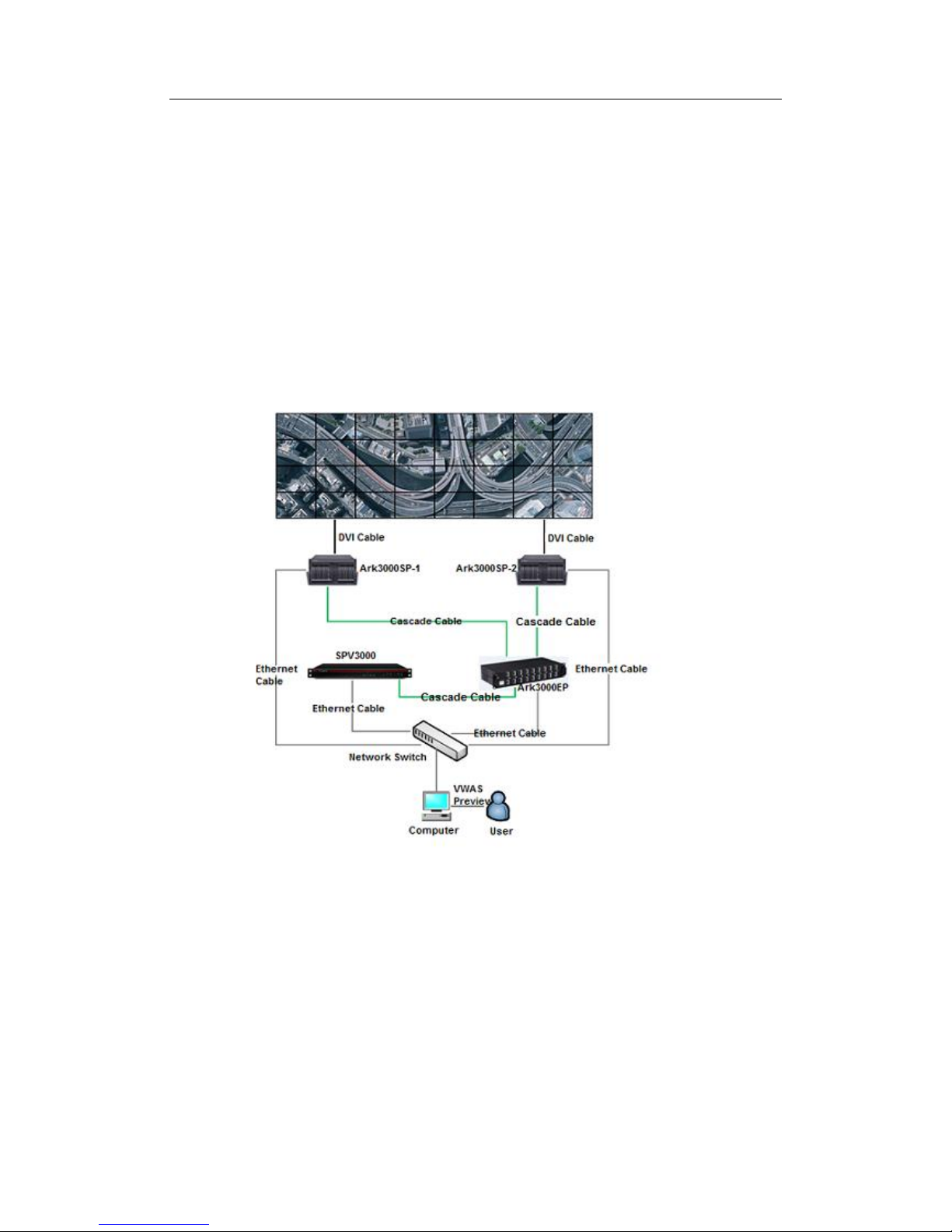
1.2.2 Functions and Features of SPV3000 Signal Preview Processor (Optional)
Digicom SPV3000 signal preview processor is mainly used to preview the input signal from
Ark3000SP. With the help of VWAS it can realize multiple preview modes: 1 image, 4 images or 8
images on single screen . A single SPV3008 can preview up to 8 channel signals, while SPV3016
can preview up to 16 channels. Moreover, a SPV3000 supports local DVI output to display current
preview content directly on a monitor. The signal preview processor mainly encodes the video
signal processed by Ark3000 into standard H.264 bit stream to achieve the preview function.
The detailed practical application is shown as below.
Page 14

User Manual Digicom3100SP Multi-screen Processor
7
Detailed features of SPV3000 signal preview processor are as below:
1) Input and output ports: support DVI ports and PCI-E ports(ports used to deal with high-speed
cascade signal)
2) Input signal quantity: support 8/16 channels high-speed cascade signal inputs;
3) Supported Preview signal types: video, RGB, VGA, HDMI, DUALLINK-DVI, DP, SDI, IP,
YPBPR signals;
4) SPV3008 supports up to 8 channels real-time preview signals, while SPV3016 supports up to
16 channels;
5) SPV3000 can work accompanied with ARK3000 processor and EP cascade device;
6) Accompanying with VWAS6.0 the SPV3000 can have a good systematic control over all
signals inputted to multiple processors and preview all these signals in real time.
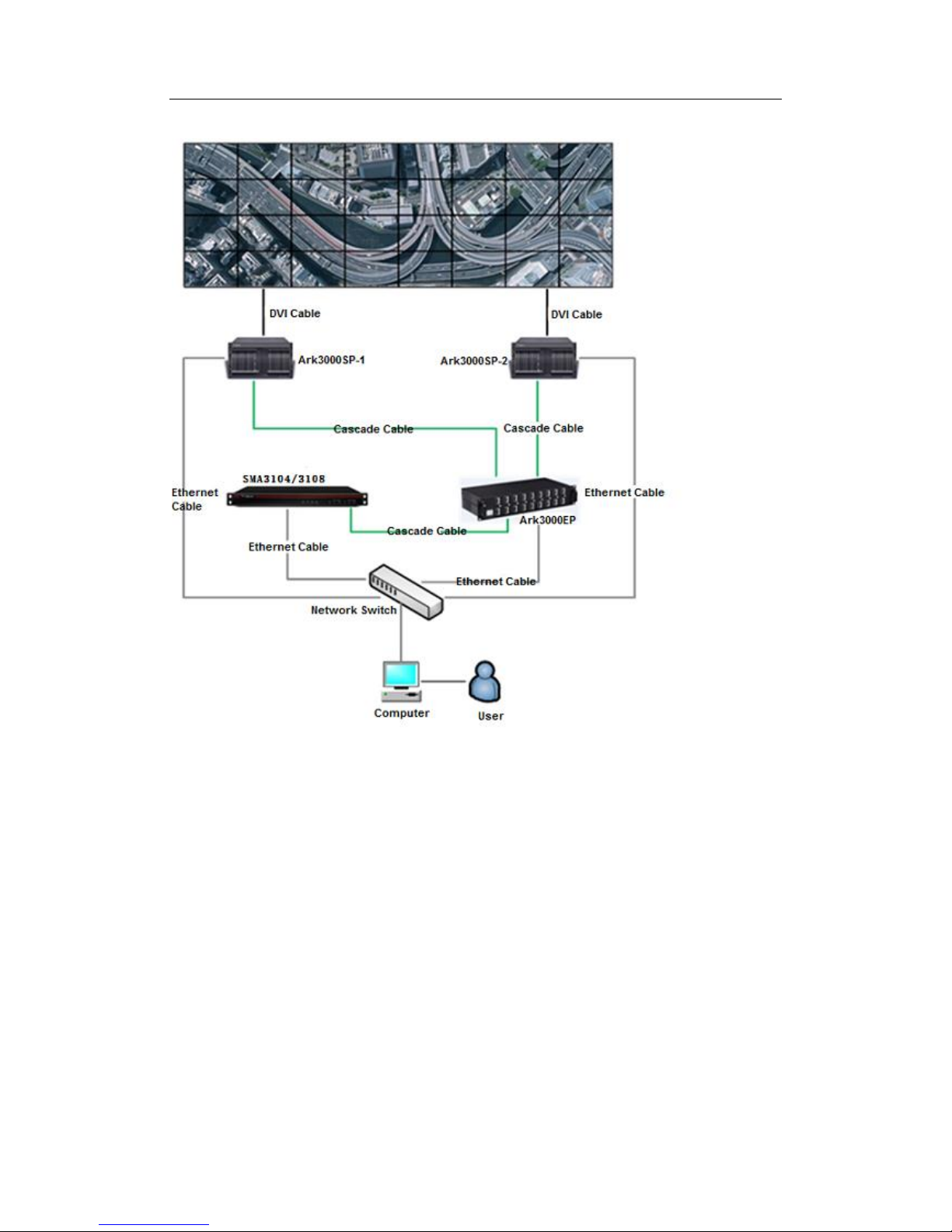
1.2.3 Functions and Features of SMA3000 Streaming Media Processor (Optional)
Digicom SMA3104/SMA3108 Streaming Media Processor is mainly used to convert the
input signal from Ark3000SP into IP signal. With the help of VWAS, a single Digicom SMA3104
can output up to 4 channels of IP video signals while a single Digicom SMA3108 can output 8
channels. Digicom SMA3104/SMA3108 Streaming Media Processor is mainly used to encode the
video signal processed by Ark3000 into standard H.264 bit stream to achieve network
transmission of Video signals.
The detailed practical application is shown as below:
Page 15
User Manual Digicom3100SP Multi-screen Processor
8
Detailed features of Digicom SMA3104/SMA3108 Streaming Media Processor are as below:
1) Input and output ports: support PCI-E ports(ports used to deal with high-speed cascade signal;
2) Input signal quantity: support 4/8 channels high-speed cascade signal inputs;
3) Supported Signal types : Video, RGB, VGA, HDMI, SDI, IP and YPBPR signals;
4) A single Digicom SMA3104 can output up to 4 channels of IP video signals while a single
Digicom SMA3108 can output up to 8 channels of IP video signals;
5) Digicom SMA3104/SMA3108 Streaming Media Processor can work accompanied with
ARK3000 processor and EP cascade device.
Page 16

User Manual Digicom3100SP Multi-screen Processor
9
1.3 Appearance
1.3.1 Digicom Ark 3100SP Multi-screen Processor
Front panel (as in the figure below): Signal acquisition board takes eight slots, which are used for
the signal acquisition of RGB signals, VIDEO signals, Dual-link signals, HDMI signals, DP
signals and SDI signals; system main control board has one slot, which is used for the dispatch of
the signal processing unit (the system main control board has two signal extension switching ports:
one is input port and another is output port); signal processing board has eight slots, which are
used for the scaling and superposition of signals.
Fig. 1-3 Front panel
Signal processing board
System control board
Desktop processing board
Signal acquisition
Dust-proof net
module
System fan module
Page 17
User Manual Digicom3100SP Multi-screen Processor
10
Note:
1. Please refer to the Introduction of Boards for the specific functions of every board.
2. The board category and amount available on site depend on the order. The figure above
is for description only.
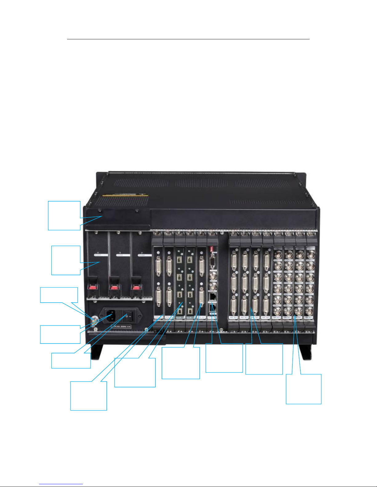
Rear panel (as in the figure below): power supply, signal I/O port, network interface, controlling
interface, clock, and synchronization signal I/O port.
Fig. 1-4-1 Rear panel 1(with DVI desktop signal input)
Video signal
input port
RGB signal
input port
Video signal
output
Power
module
Power switch
Power outlet
Grounding
Main control
board
Power fan
module
Optical signal
output
DVI desktop
signal input
Page 18
User Manual Digicom3100SP Multi-screen Processor
11
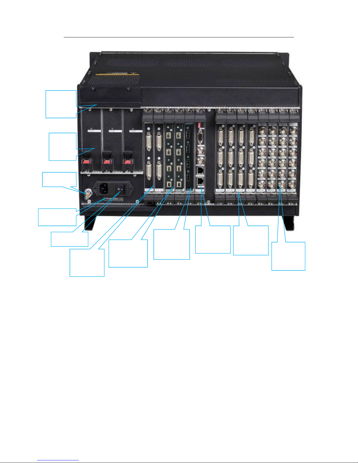
Fig. 1-4-2 rear panel 2(with DP desktop signal input)
Video signal
input port
RGB signal
input port
Video signal
output
Power
module
Power switch
Power outlet
Grounding
Main control
board
Power fan
module
Optical signal
output
DP desktop
signal input
Page 19

User Manual Digicom3100SP Multi-screen Processor
12
Fig.1-5 Dual-link signal input port
Fig.1-6 HDMI signal input port
Fig.1-7 DP signal input port
Page 20
User Manual Digicom3100SP Multi-screen Processor
13
Fig.1-8 SDI signal input port
Fig.1-9 Optical signal input port
Fig.1-10 IP signal input port
Page 21

User Manual Digicom3100SP Multi-screen Processor
14
Fig. 1-11 system control port
Note:
The board category and amount available on site depend on the order. The figure above is for
description only.
DIP switch of Device No.
Serial port (not for control)
Clock/synchronization signal output port
Clock/synchronization signal input port
Network port 1
Network port 2
System reset switch
Page 22

User Manual Digicom3100SP Multi-screen Processor
15
1.3.2 SPV3000 Signal Preview Processor(Optional)
Front view: 6 LED indicator and cascade input/output ports
Fig.1-12 Front view of Signal preview processor
Rear view: signal ports (including DVI input and output ports, DIP switch, and two LAN
ports, etc.), and two power input ports;
Indictor
Color
Function
RUN
Green
Indicating the board’s working status. Blinking
when board works well.
ALARM
Red
Indicating the board’s working status. Blinking
when abnormality appears.
POWER1
Green
Indicating the board’s working status. Lighting
constantly when power 1 works well
POWER2
Green
Indicating the board’s working status. Lighting
constantly when power 2 works well.
Table 1-1 Digicom SPV3000 signal preview processor working status
Overall view:
Fig 1-13 Rear view of signal preview processor
Cascade signal output port
Cascade signal input port
Page 23

User Manual Digicom3100SP Multi-screen Processor
16
Signal ports snapshot
Fig 1-14 Signal ports snapshot
Power ports snapshot:
Fig 1-15 Power ports snapshot
1.3.3 SMA3000 Streaming Media Processor
Front view: 6 LED indicator and cascade input/output ports
Fig.1-16 Front view of Streaming Media Processor
DVI signal input port
DVI signal output port
DIP switch
Reset button
Signal output port
LAN ports
Power input port
Power input port
Cascade signal output port
Cascade signal input port
Page 24

User Manual Digicom3100SP Multi-screen Processor
17
Rear view: signal ports (including DVI input and output ports, DIP switch, and two LAN
ports, etc.), and two power input ports;
Indictor
Color
Function
RUN
Green
Indicating the board’s working status. Blinking
when board works well.
ALARM
Red
Indicating the board’s working status. Blinking
when abnormality appears.
POWER1
Green
Indicating the board’s working status. Lighting
constantly when power 1 works well
POWER2
Green
Indicating the board’s working status. Lighting
constantly when power 2 works well.
Table 1-2 Digicom Streaming Media Processor working status
Overall view:
Fig 1-17 Rear view of Streaming Media Processor
Page 25

User Manual Digicom3100SP Multi-screen Processor
18
Signal ports snapshot
Fig 1-18 Signal ports snapshot
Power ports snapshot:
Fig 1-19 Power ports snapshot
1.4 Technical Specifications
Digicom Ark 3100SP Multi-screen Signal Processor
Hardware
Specifications
Bus bandwidth
280Gb/S
Controlling
interface
RJ45 gbps
network interface
2 100/1000 mbps adaptive Ethernet ports, using category-6 twisted copper wire to connect to
switch
RS232 serial port
1 DB9 serial port, used for system detection and test
Reset switch
System reset
Desktop input
DMS59
connector
Support Dual-Link independent desktop input
DIP switch
Reset button
Debug port
LAN ports
Power input port
Power input port
Page 26

User Manual Digicom3100SP Multi-screen Processor
19
Support 1-4 channels of Dual-link desktop input, each DMS59 interface can access 2
channels of DVI-D Dual-Link signal input;
DisplayPort
connector
Support DisplayPort independent desktop input
Support 1-4 channels of DP desktop input, each DP interface can access 1 channel of DP
signal input;
Support Digicom Magic desktop server access;
Graphics
processing –
output(two for
optional)
DMS59
connector
(DVI port)
One processor can access up to 16 channels of signal output
4 channels of video output board, “4-channel of /board” DVI-D signal output:
Each board uses two DMS59 output interfaces, each DMS59 interface can support two
channels of DVI-D signal output;
Support up to 4 video output boards access, meaning totally 16 channels of digital signal
output;
Supported overlapping windows:
One channel supports superposition of up to 8 overlapping windows; signal superposition
achieves the Alpha transparency effect;
Output resolution range: 1024x768@60Hz, 1366x768@50Hz, 1366x768@60Hz,
1400x1050@60Hz, 1600x1200@60Hz, 1920x1080@60Hz, 1920x1200@60Hz;24bit color
depth.
LC-fiber
connector
(optical fiber
port)
One processor can support up to 16 channels of signal output
4 channels of video output board, “4-channel/board” optical signal output:
Each board uses four LC output interfaces, and each LC interface can support one channel of
optical signal output;
Support up to 4 video output boards access, meaning totally 16 channels of digital signal
output;
Supported overlapping windows:
One channel supports superposition of up to 8 overlapping windows; signal superposition
achieves the Alpha transparency effect;
Output resolution range: 1024x768@60Hz, 1366x768@50Hz, 1366x768@60Hz,
1400x1050@60Hz, 1920x1080@60Hz;24bit color depth.
RGB signal
input
DMS59
connector
“6-channel of RGB/board” input: each board uses 3 DMS59 output interfaces, each DMS59
interface can access 2 channels of DVI-D DRGB or 2 channels of VGA ARGB or 2 channels
of BNC ARGB input
Supported DRGB resolution: 640x480@85Hz~1600x1200@60Hz
Support Single-Link DVI-D signal: including 1920x1080@60Hz and 1920x1200@60Hz
with narrowband ) , Signal bandwidth: not over 165MHz
Supported ARGB resolution: 640x480@85Hz~1600x1200@60Hz
including 1920x1080@60Hz and 1920x1200@60Hz with narrowband ) , Signal bandwidth:
not over 165MHz
One processor can access up to 8 RGB signal acquisition boards, “6-channel of RGB/board”
access, and up to 48 channels of RGB signal input
Support any resolution, any magnification and 30fps refreshing frequency in 24-bit color
depth;
Integrate auto/manual format recognition function (AUTO/ Manual), and allow checking the
format in AUTO mode;
The user can edit the signal formats and save them for detection; support all VESA standard
formats and customized formats;
Video signal
input
BNC interface
“6-channel of Video/board” input: support CVBS signals in PAL/NTSC system, and
3-channel of S-Video/board input.
One processor can access up to 8 Video signal acquisition boards, “6-channel of
Video/board” access, and up to 48-channel of Video signal input;
Integrate auto/manual format recognition function (AUTO/PAL/NTSC), and allow checking
the format in AUTO mode;
Supported Video signal and refreshing frequency: PAL:25fps; NTSC:30fps
Page 27

User Manual Digicom3100SP Multi-screen Processor
20
Optical signal
input
LC-fiber
connector
(optical fiber
port)
4 channels for each board; support optical signal input (which is transformed from
Single-Link DVI-D signal)
Resolution: 640x480@60Hz~1920x1080@60Hz;24 bits
HDMI signal
input
HDMI port
6 channels for each board. One processor can access up to 8 pieces of HDMI board, which
means 48 channels of HDMI signal.
Support HDMI standard signal input
DUAL-LINK
signal input
DVI-D port
2 channels of signal input for each board. One processor can access up to 8 pieces of
DUAL-LING signal acquisition board, which means 16 channels of DUAL-LINK signal
input.
The maximum resolution supported: 4088×4088@30Hz
DP signal input
DP port
2 channels of signal input for each board. One processor can access up to 8 pieces of DP
signal acquisition board, which means 16 channels of Display Port signal input.
The maximum resolution supported: 4096×4088@30Hz(signal in DP1.1a standard)
SDI signal input
BNC port
4 channels of signal input for each board. One processor can access up to 8 pieces of SDI
signal acquisition board, which means 32 channels of SDI signal input.
SDI signal: HD-SDI and 3G-SDI
IP signal input
Network port
Each board supports 4 channels of 1080p@60Hz signal, 16 channels of D1signal or 4
channels of audio signal; One processor can access up to 8 pieces of IP signal acquisition
board, which means 32 channels of 1080P signal, 126 channels of D1 signal or 32 channels
of audio signal.
Signal formats: CIF,D1,1080P
Hot- plugging
function
System power supply, fan, boards support hot-plugging
Processor size
W × H ×D=482.6 x 265.9 x 523 mm
19" standard rack, one processor is 7U high (including 1U extension), top rack is 10U high (including 2U air inlet
path and 2U air outlet path), complying with GB/T 3047.2-1992, GB/T 19520-2004, PICMG2.0 D3.0, IEC
60297.2, ANSI/EIA RS-310-D
Weight (net)
< 42Kg
Power supply
Power
specifications
N+1 hot redundant hot system power supply, support hot-plugging
Electrical
characteristics
~100-240V 50/60Hz 8-4A
Rated power
< 750W
Operating environment
Operating fan
3 hot redundant fans , support hot-plugging
Operating
environment
Temperature: 0℃-40℃
RH: 20%-80% (no condensing)
Software
System
controlling
software
VTRON VWAS Standard (optional); VLinkExpress (optional)
Page 28

User Manual Digicom3100SP Multi-screen Processor
21
SPV3000 Signal Preview Processor(Optional )
Hardware
Specifications
External port
DC power port
External DC power input port*2
DVI port
DVI port*3
RJ45 100M port
100M/1000M LAN port*2
Device number DIP switch (4 bits address)*1
Reset button*1
Signal expansion
PCIEx4
high-speed signal
port
High-speed signal expansion input/output port*8
Support 8 channels & 16 channels expansion window signal roaming on the entire wall
LED indicator
Running indicator*3 (power indicator 1, power indicator 2, working indicator)
Alarm indicator*1 (Alarm indicator)
Power
two Redundant power inputs
Rated power
consumption
≤30W
Rated voltage
12V DC 6.66A
Chassis
Dimension
1U, standard 19” specialized mounted server chassis, W×H×D=482.6mm X 43mm X
208mm
Fan
Two cooling fans
Working environment
Temperature: 0℃-40℃Relative humidity: 20%-80%(No condensing)
Weight
≦17Kg
SMA3000 Streaming Media Processor (Optional )
Hardware
Specifications
External port
DC power port
External DC power input port*2
DVI port
DVI port*3
RJ45 100M port
10M/100M/1000M LAN port*2
Device number DIP switch (4 bits address)*1
Reset button*1
PCIEx4 high-speed signal port
High-speed signal expansion input/output port*8
Can convert 4 channels of input signal from Ark3000SP into IP signal.
LED indicator
Running indicator*3 (power indicator 1, power indicator 2, working indicator)
Alarm indicator*1 (Alarm indicator)
Power
two Redundant power inputs
Rated power
consumption
≤30W
Rated voltage
12V DC 5.0A
Chassis
Dimension
1U, standard 19” specialized mounted server chassis, W×H×D=482.6mm X 43mm X
208mm
Fan
Two cooling fans
Page 29

User Manual Digicom3100SP Multi-screen Processor
22
Working environment
Temperature: 0℃-40℃
Relative humidity: 10%-90%(No condensing)
Weight
≦6Kg
Note:
1. In actual system configuration, the amount of display boards, RGB input boards and
video input boards depend on the project. Please contact VTRON or agent for details.
2. To exert the effect of the hardware, the user may need to purchase other peripheral
equipment.
3. The specifications are subject to changes without prior notice.
4. The actual product configuration bases on the order.
1.5 Classical Application Diagram
Fig.1-20 System structure diagram
Page 30

User Manual Digicom3100SP Multi-screen Processor
23
2. Introduction to Boards
2.1 System Main Control Board
In Digicom Ark 3100SP Multi-screen Processor, system main control board consists of SCA-385
(Fig.2-1) and SCA-301 (in Fig.1-11). It can be placed at the ninth slot on the left side (on the front
panel). It is the core function control board.
System main control board is responsible for all communication business between the processor
and the external PC, and control all of the boards according to the command of the controlling PC.
System main control board is also responsible for scheduling serial video signal to each board.
The access signal of the whole system can be cross-scheduled with non-blocking and powerful
real-time, and display anywhere within the corresponding display cube.
Fig.2-1 Appearance of system main control board SCA-385
The functions and features of system main control board:
Integrate the dispatch function of the entire Multi-screen signal processor and the
business boards to complete related tasks;
Provide device No. DIP switch for device No. IP address setting;
Monitor the temperature and power supply state of every module and send alarm
message of abnormity to the user;
Integrate self-diagnosis function, making the system maintenance and upgrade more
convenient;
If the temperature of Multi-screen processor system is too high, the system will enter
Page 31

User Manual Digicom3100SP Multi-screen Processor
24
low power consumption state to reduce power consumption and ensure system security;
Support hot-plugging to minimize the time for maintenance;
LED indicators of board working status, please refer to form2-1.
Symbol name
status
indication
RUN
Flash slowly(0.5 seconds
interval)
Normal
Flash quickly(0.2 seconds
interval)
Upgrading
Black out or not flashing
Abnormal
ALARM
Flash quickly(0.2 seconds
interval)
Alarm
Flash slowly(0.5 seconds
interval)
Minimum system
Form 2-1 Board working status
2.2 Signal Processing Board
In Digicom Ark 3100SP multi-screen processor, the signal processing board consists of GPA-325
(Fig.2-2) and GPA-340 (in Fig.1-4). GPA-325 can be placed in any slot within the 8 slots at
right-most side on the front. Each signal processing board supports up to two output display cubes,
and supports overlapping of 8 signal windows and one channel of desktop signal. The entire
system supports up to 8 signal processing boards and supports 16 output display cubes.
Fig.2-2 Appearance of signal processing board GPA-325
Page 32

User Manual Digicom3100SP Multi-screen Processor
25
The functions and features of signal processing board:
Features zooming in/out and overlapping for signal window and desktop signal;
Output signal through DMS-59 to standard digital interface (DVI-D) with an output
resolution up to 1900×1200@60Hz;
Provide test circle, checkerboard, color stripe, gray scale and VTRON LOGO test
patterns;
Support alarm report function;
Integrate self-diagnosis function, making the system maintenance and upgrade more
convenient;
Support hot-plugging, minimizing the time for maintenance;
LED indicators of board working status, please refer to form2-1.
2.3 Audio Signal Expansion Processing Board
Audio expansion processing board consists of EMA-385 (Fig.2-3) and MPA-325 (Fig.1-5).
EMA-385 can only be placed at the 8th slot of the front panel (Fig.1-3) (counting from right) and
MPA-325 can only be placed at the 4th slot of the rear panel (Fig.1-4) (counting from left). A
single Audio expansion processing board can support 8-channel mono audio signal acquisition and
8-channel mono audio signal output.
Fig.2-3 Appearance of Audio signal expansion processing board EMA-325
Page 33

User Manual Digicom3100SP Multi-screen Processor
26
The functions and features of Audio signal expansion processing board:
Support cascade signal input/output and DVI signal output;
Support alarm report function;
Integrate self-diagnosis function, making the system maintenance and upgrade more
convenient;
Support hot-plugging, minimizing the time for maintenance;
LED indicators of board working status, please refer to form2-1.
2.4 RGB Signal Acquisition Board (Optional)
RGB signal acquisition board consists of RA-365 (Fig.2-4) and RA-361 (in Fig.1-4). RA-365 can
be placed at any slot (Fig.1-3) within the 8 slots at left-most side. The entire system supports up to
8 pieces of RGB signal acquisition boards, and each board can signal acquisition 6 channels of
ARGB signal input or 6 channels of DRGB signal input.
Fig.2-4 Appearance of RGB signal acquisition board RA-365
The functions and features of RGB signal acquisition board:
Support RGB signal input in ARGB, DRGB and HDMI mode;
Support 24-bit color depth;
Page 34

User Manual Digicom3100SP Multi-screen Processor
27
The control connects to main control board through Ethernet or serial port
communication;
Support signal cutting; the cutting signal displaying and image freezing;
Automatically recognize signal format and adjust the corresponding sampling
parameters quickly when the input source changes;
Support ARGB automatic white balance, i.e. when inputting white image test signals,
the signal gain can be optimized by executing automatic white balance command;
Alarm report of collection source signal, abnormity, input switching, format change and
format error;
Integrate self-diagnosis function, making the system maintenance and upgrade more
convenient;
Support hot-plugging, minimizing the time for maintenance;
LED indicators of board working status, please refer to form2-1.
Page 35

User Manual Digicom3100SP Multi-screen Processor
28
2.5 Video Signal Acquisition Board (Optional)
Video signal acquisition board consists of VA-365 (Fig.2-5) and VA-361 (in Fig.1-4). VA-365 can
be placed at any slot (Fig.1-3) within the 8 slots at left-most side. Each processor can access up to
8 pieces of Video signal acquisition board and each board can support 6 channels of CVBS signal
input or 3 channels of S_VIDEO signal input.
Fig.2-5 Appearance of video signal acquisition board VA-365
The functions and features of video signal acquisition board:
Each board can input 6 channels of CVBS or 3 channels of S-VIDEO signals;
Automatically recognize signal format when the input source changes;
Supports alarm report;
Supports image freezing of the signal source;
Integrate self-diagnosis function, making the system maintenance and upgrade more
convenient;
Support hot- plugging, minimizing the time for maintenance;
LED indicators of board working status, please refer to form2-1.
Page 36

User Manual Digicom3100SP Multi-screen Processor
29
2.6 Dual-Link Signal Acquisition Board (Optional)
Dual-Link signal acquisition board consists of DRA-325 (Fig.2-6) and DRA-321 (in Fig.1-5).
DRA-325 can be placed at any slot (Fig.1-3) within the 8 slots at left-most side. Each processor
supports up to 8 pieces of Dual-Link DVI signal acquisition board and each board can support 2
channels of Dual-link signal input. The maximum resolution supported by the first channel of
Dual-Link DVI signal acquisition board is up to 3840×2400@30, and the second channel’s
resolution is up to 3840×1200@60.
Fig.2-6 Dual-Link signal acquisition board DRA-325
The functions and features of dual-link signal acquisition board:
Dual-Link signal acquisition board accomplish the work based on the command coming
from the system main control board;
Dual-link signal window supports one layer of window’s overlapping;
The maximum input signal resolution is up to 3840×2400@30;
Automatically recognize signal format when the input source changes;
Supports adding or modifying the resolution online;
Supports image freezing of the signal source;
Supports alarm reporting;
Integrate self-diagnosis function, making the system maintenance and upgrade more
convenient;
Page 37

User Manual Digicom3100SP Multi-screen Processor
30
Support hot-plugging, minimizing the time for maintenance ;
LED indicators of board working status, please refer to form2-1.
2.7 HDMI Signal Acquisition Board (Optional)
HDMI signal acquisition board consists of RA -365 (Fig.2-7) and HA-361 (in Fig.1-6). RA-365
can be placed at any slot (Fig.1-3) within the 8 slots at left-most side. Each processor supports up
to 8 pieces of HDMI signal acquisition board and each board can access 6 channels of HDMI
signal input.
Fig.2-7 HDMI signal acquisition board RA-365
The functions and features of HDMI signal acquisition board:
HDMI signal acquisition board accomplishes the work based on the command coming
from the system main control board;
Support HDMI signal input;
Supports image freezing of the signal source;
Supports alarm reporting;
Integrate self-diagnosis function, making the system maintenance and upgrade more
convenient;
Support hot-plugging, minimizing the time for maintenance ;
LED indicators of board working status, please refer to form2-1.
Page 38

User Manual Digicom3100SP Multi-screen Processor
31
2.8 DisplayPort Signal Acquisition Board (Optional)
DP signal acquisition board consists of DPA-325 (Fig.2-8) and DPA-321 (in Fig.1-7). DPA-325
can be placed at any slot (Fig.1-3) within the 8 slots at left-most side. Each processor supports up
to 8 pieces of DP signal acquisition board and each board can access 2 channels of DP signal
input.
Fig. 2-8 DP signal acquisition board DPA-325
The functions and features of DP signal acquisition board:
Support 24-bit color depth;
When the input source changes, the board could identify the signal format automatically,
and set the appropriate sampling parameters quickly;
Alarm reporting for signal abnormalities, input signal switching, format changing, and
incorrect format;
Temperature monitoring with an alarm indicator;
Integrate self-diagnosis function to make the system maintenance and upgrade more
convenient;
Support hot-plugging, minimizing the time for maintenance;
LED indicators of board working status, please refer to form2-1.
Page 39

User Manual Digicom3100SP Multi-screen Processor
32
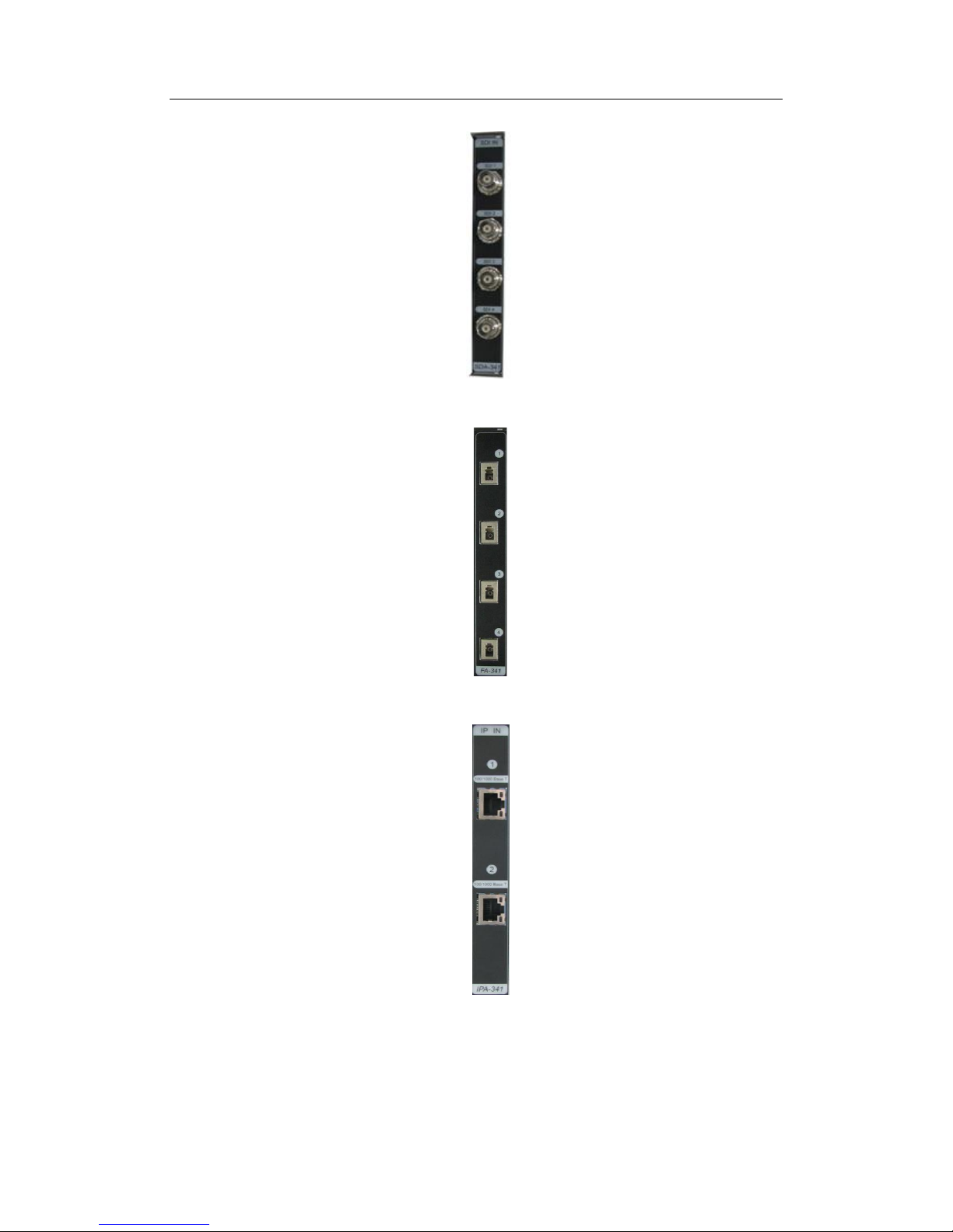
2.9 SDI Signal Acquisition Board(Optional)
SDI signal acquisition board consists of SDA-345 (Fig.2-9) and SDA-341 (in Fig.1-8). SDA-345
can be placed at any slot (Fig.1-3) within the 8 slots at left-most side. Each processor supports up
to 8 pieces of SDI signal acquisition board and each board can support 4 channels of SDI signal
input. Three kind of signal format can be supported: SD-SDI, HD-SDI and 3G-SDI.
Fig. 2-9 SDI signal acquisition board SDA-345
The functions and features of SDI signal acquisition board:
Support color space of YCbCr4:2:2;
When input source changes, the board could identify the signal format automatically,
and adjust the appropriate sampling parameters quickly;
Temperature monitoring with an alarm indication indicator;
Integrate self-diagnosis to make the system maintenance and upgrade more convenient;
Support hot-plugging, minimizing the time for maintenance;
LED indicators of board working status, please refer to form2-1.
Page 40

User Manual Digicom3100SP Multi-screen Processor
33
2.10 Optical Signal Acquisition Board (Optional)
The optical signal signal acquisition is jointly performed with RA-365 (Figure 2-3) paired
with optical signal input interface board FA-341 (Fig. 2-10-1). FA-341 can be located in any one
of the 8 slots from the right at the back of the product (see Fig. 1-4). In practical applications, the
signal source should be used together with a DVI to optical-fiber transmitter (see Figure 2-10-2).
Fig.2-10-1 FA-341
Fig.2-10-2 FA-341 and the transmitter
The specific functions of FA-341 are as follows:
Long-distance DVI signal transmission can be realized with a single-core and
multi-mode optical fiber cable and the maximum transmission distance can be 300m;
The transmission speed is 5.0Gbps
Support a DVI video resolution up to 1080p@60Hz 24-bit color depth
Meet the requirement on reliability of optical module: TELCORDIAGR-468
No RFI/EMI radiation or video quality attenuation, ensuring data security
Support hot plugging, minimizing troubleshooting time.
Page 41

User Manual Digicom3100SP Multi-screen Processor
34
2.11 Optical Signal Output Board (Optional)
The optical signal output is performed by GPA-325 (Figure 2-2) paired with the optical signal
output interface board GFA-340 (Figure 2-11) jointly. GFA-340 can be placed at any one of the
first 4 slots from the left at the back of the product (see Figure 1-4). In practical application, the
optical signal output board sshould be used together with a DVI to optical-fiber receiver (similar
as the transmitter, see Figure 2-10).
Fig.2-11 GFA-340
The specific functions of GFA-340 are as follows:
The long-distance DVI signal transmission can be realized with a single-core and
multi-mode optical fiber cable and the maximum transmission distance can be 300m;
The transmission speed is 4.5Gbps;
Support a HDMI video resolution up to 1080p@60Hz 24-bit color depth;
Meet the requirement on reliability of optical module: TELCORDIAGR-468;
Real plug and play, no manual EDID setting is required;
Signal re-clocking, no TMDS extension, so as to reduce clock deviation;
No RFI/EMI radiation or video quality attenuation, ensuring data security.
Page 42

User Manual Digicom3100SP Multi-screen Processor
35
2.12 IP Streaming Signal Acquisition Board(Optional)
IP streaming signal acquisition board consists of IPA-345 (Fig.2-12) and IPA-341 (in Fig.1-10).
IPA-345 can be placed at any slot (Fig.1-3) within the 8 slots at left-most side. Each processor
supports up to 8 pieces of IP streaming signal acquisition board and each board can support 4
channels of 1080p signal input, 16 channels of D1 signal input and support to decode 4 channels of
audio signal in IP format.
Fig. 2-12 IP streaming signal acquisition board IP A-345
The functions and features of IP signal acquisition board:
Support IP streaming signal input
Support 12-bits color depth;
Support signal cutting function: Any part of the input signals can be cut and displayed
out;
If the input source changes, the board could identify the signal format automatically, and
adjust the appropriate sampling parameters quickly;
Temperature monitoring with an alarm indicator;
Integrate self-diagnosis to make the system maintenance and upgrade more convenient;
Support hot-plugging, minimizing the time for maintenance;
Page 43

User Manual Digicom3100SP Multi-screen Processor
36
LED indicators of board working status, please refer to form2-1.
2.13 Desktop Processing Board (Optional)
1) DVI desktop signal processing board(optional)
Desktop processing board consists of DA-35(Fig. 2-13-1) and DA-341 (refer to Fig.1-4).The
desktop processing board decodes the input HD image signals to lower resolution parallel RGB
pixel data signal, performing corresponding treatment according to system configuration and then
send to video processing board.
Fig.2-13-1 Desktop processing board DA-35
The functions and features of desktop signal processing board:
Desktop signal processing board accomplish the work based on the command coming
from the system main control board;
To support Dual-link DVI signal input;
Each board can support 4 channels of DVI-D desktop signal input;
Supports alarm reporting;
Integrate self-diagnosis function,, making the system maintenance and upgrade more
convenient;
Support hot-plugging, minimizing the time for maintenance;
About the LED indicators of board working status, please refer to form2-1.
Page 44

User Manual Digicom3100SP Multi-screen Processor
37
2) DP desktop signal processing board (optional)
Desktop processing board consists of DPA-35(Fig. 2-13-2) and DPA-341 (refer to Fig.1-4).The
desktop processing board decodes the input HD image signals to lower resolution parallel RGB
pixel data signal, performing corresponding treatment according to system configuration and then
send to video processing board.
Fig.2-13-2 Desktop processing board DA-35
The functions and features of desktop signal processing board:
Desktop signal processing board accomplishes the work based on the command coming
from the system main control board;
To support Dual-link DP signal input;
Each board can access 4 channels of DVI-D desktop signal input;
Supports alarm reporting;
Integrate self-diagnosis function, making the system maintenance and upgrade more
convenient;
Support hot-plugging, minimizing the time for maintenance;
LED indicators of board working status, please refer to form2-1.
Page 45

User Manual Digicom3100SP Multi-screen Processor
38
2.14 Live View Board (Optional)
MVA-385 live view board supports wall live view (live view for desktop and signal window). One
Ark processor supports one live view board. Only when the Ark processor is embedded with a live
view board, can the whole-wall live view function be available.
Fig.2-14 Live view board MVA-385
The functions and features of the live view board are shown as below:
Supports local output;
The HDMI port of the board supports at least one-channel 1080P decoding output;
Supports wall live view function;
Supports standard H.264 RTSP and HIPC protocols;
Supports 1080P30 IP network signal live view;
Supports hot-swappable function.
Page 46

User Manual Digicom3100SP Multi-screen Processor
39
3. Installation
Precautions
1) The on-site installation should be performed by qualified technical engineers. Please
consult VTRON or agent before installing to get technical guidance. To ensure the safety
of the device and installers, at least two technicians are required to complete the
installation.
2) Digicom Ark 3100SP Multi-screen Processor is delivered as a complete device. All the
hardware installation procedures of the Multi-screen signal processor have been
completed according to the production process strictly in the factory, and had passed the
high temperature and aging test. The user only needs to connect the Multi-screen signal
processor to peripheral equipment.
3) Before installing the Multi-screen signal processor, please check whether the
environment complies with the requirement of Multi-screen signal processor on working
environment (e.g. temperature, RH, power supply, grounding system, etc.), so as to
ensure that the device can be used normally after installing and also ensure the service
life of the device.
4) Please use the provided cables (including signal cable, network cable, power cord, etc.).
If it is necessary to use other cables, please consult VTRON or agent before installing to
get technical guidance.
Main cables include:
Video signal cable Signal cascade cable Power cable
Page 47

User Manual Digicom3100SP Multi-screen Processor
40
HDMI signal cable Signal output adapter cable
Dual-link signal cable Extension Cable Kit for DVI signal
SDI signal cable DP signal cable
The cable pictures above are only for reference, about details of supplied cable, please
refer to the items on the packing list.
Page 48

User Manual Digicom3100SP Multi-screen Processor
41
3.1 About packing List
Note:
After unpacking, please check the amount according to the packing list; if any part is
missing, please contact the supplier. The packing list is in the package.
The appearance figures of the product/parts in this manual are for description only. The
real product may be different.
Please keep the packing materials properly for future use.
Page 49

User Manual Digicom3100SP Multi-screen Processor
42
3.2 Installing the Cabinet
Digicom Ark 3100SP Multi-screen Processor is in standard modular design, making it has high
expansibility. With redundant power supply and redundant fan, the system stability and excellent
cooling effect are ensured, and the system performance of the Multi-screen signal processor is also
improved. The independent wiring bracket makes the installation and wiring easier.
Digicom Ark 3300SP Multi-screen Processor can be installed in professional 19” rack mounting
cabinet;
3.2.1 Rack Mounting
In rack mounting mode, the Multi-screen signal processor and other equipment on-site are
installed in the professional cabinet together. The support in the bottom of the chassis should be
removed, and install inlet plate on the bottom and ventilation plate on the top. While installing,
adjust the distance between the installation bar of the cabinet and the front door to 50mm~100mm.
Use the provided dedicated bolts to fix. In rack mounting mode, the handle on front panel of the
chassis can be removed. The outlet cable in the end of the cabinet can be fixed on the wiring
structure of the cabinet, or fixed with the optional Cabling Bracket in the cabinet.
Note: The cabinet is purchased separately. In this installation mode, the selected cabinet should
comply with IEC 60297. The recommended specification is 600 * nU (height) * 1200 (depth),
where “n” depends on the amount of on-site installation devices. Please consult VTRON or agent
for the purchase of cabinet.
3.2.2 Cabling Bracket
When installing the chassis, you can select the cabling structure of the cabinet or the cabling
bracket designed by VTRON to facilitate the system cabling and future maintenance.
The cabling bracket designed by VTRON is as shown in the following figure:
Page 50

User Manual Digicom3100SP Multi-screen Processor
43
The cabling bracket shall be mounted to the rear frame of the cabinet behind the chassis to save
the space.
When connecting the relevant interfaces on the rear panel of the chassis, please pass the cables
through the cabling bracket slots and then properly lay the relevant cables on the cabling bracket
according to the principle of proximity.
3.3 Connecting Display Device
Connect every output interface of the signal processing board of Digicom Ark 3100SP
Multi-screen Processor to the corresponding input interface of the display device with the matched
signal cables.
Note:
Since digital signals have strict limit on transmission distance, it is recommended to
select the signal cables provided by VTRON. If it is necessary to use other signal cables,
please consult VTRON or agent first.
Please note the plug position of the connector when use the cable to connect the
device(refer to the diagram), reducing the probability of mis-mating..
Page 51

User Manual Digicom3100SP Multi-screen Processor
44
3.4 Connecting Signal Source
Use the matched RGB signal cable to connect the RGB signal input interface of Digicom Ark
3100SP Multi-screen Processor to the output interface of RGB signal source; use video signal
cable to connect the video input channel of Digicom Ark 3100SP Multi-screen Processor to the
output channels of video signal source.
At on-site, RGB signal sources usually refer to working PC, professional workstation or matrixes
connected to these devices. The video signal sources are in various types, including common
video players and recorders. Since there are many video input ports, please pay attention to the
port number connected to every video signal source while connecting, so that the corresponding
video signal source can be called out in the application software properly.
3.5 Connecting Network Cable
Digicom Ark 3100SP Multi-screen Processor can be working on the network, or controlled
Page 52

User Manual Digicom3100SP Multi-screen Processor
45
through the network. Therefore, please connect the Multi-screen signal processor to the network
through switching device, i.e. connect the switching devices and network ports with network
cables. Please connect the specific port according to the network condition on-site.
Ark3100SP network connection settings:
Note:
1. The controlling PC is installed with VWAS and PowerServer and has at least 2 network cards
or 2 network ports:
2. IP1 is 192.168.1.XX (XX is larger than 20), the subnet mask is 255.255.0.0 and IP2 is the LAN
segment of related equipment such as DLP or LCD display, which should be separated from IP1
LAN segment.
3. Without permission of technician for this processor, please do not connect your PC or other
network equipment directly to the switchboard of this processor.
4. Without permission of technician for this processor, please do not change the IP address of your
controlling PC.
5. Without permission of technician for this processor, please do not replace related configurations
of the processor.
6. When you have any such problem and the problem cannot be avoided with the above methods,
please contact VTRON or our dealers. We will respond to your inquiry as soon as possible.
Page 53

User Manual Digicom3100SP Multi-screen Processor
46
3.6 Connecting Power Cord
The power port of Digicom Ark 3100SP Multi-screen Processor is in the lower right corner in the
rear panel of the device, as shown below:
Please use the provided cables to connect the power port of the device and power outlet.
Unqualified power cord will affect the power supply of the equipment and thus disturb the
stability and electrical security of the device. In addition, to ensure the power supply stability of
the Multi-screen signal processor, the power port of the processor should be connected to
separated power outlet (220V10A standard receptacle is recommended) and do not share with
other devices.
3.7 System Grounding
Digicom Ark 3100SP Multi-screen Processor has two grounding points, one is embedded
grounding point of 3-core power cord and the other is shell grounding bolt. To ensure the safety
and stability of the device and safety of operators, please implement proper grounding measures,
i.e. use provided 3-core power cord. In addition, it is necessary to use dedicated grounding
conductor to connect the grounding bolt in the lower right corner on the rear panel to dedicated
grounding system in proper means.
Power outlet
Grounding
Page 54

User Manual Digicom3100SP Multi-screen Processor
47
Note:
To ensure safe operation and normal working of the system, the electrical grounding of electronic
products is compulsory. Improper grounding will disturb the reliability and stability of the system,
as well as signal quality. Therefore, please consider the grounding measures for the entire system
when install the Multi-screen signal processor, including the grounding measure of power supply
(e.g. use qualified 3-core power cord and power outlet). In addition, to install the Multi-screen
signal processor in high-rise building, the device should be grounded to dedicated grounding
system, and keep certain distance for lighting of the building. Improper grounding system has
great negative impact on the signal transmission of the device, which is presented as the images
have interference that can’t be eliminated. For more information, please consult VTRON and
maintain proper proper measures for grounding during operation.
Page 55

User Manual Digicom3100SP Multi-screen Processor
48
4. VTRON Wall Administration System (VWAS) (Optional)
VWAS (VTRON Wall Administration System) software is an administration system specially
developed, designed and manufactured by VTRON for display wall system and Multi-screen
processor system. Its main function is to manage and control the hardware resources including the
Multi-screen signal processor, and finally manage and control the signal windows and application
windows on the display wall. VWAS can exert the advantages of network distributed software
system, support simultaneous connection and operation of several clients, and provide simple,
friendly and customized human-machine interface, making the control of display wall more
convenient, visual operation and eliminating the complicated operation of conventional display
wall.
Note: For the detailed operation instructions of the VWAS software, please refer to the VWAS
software manual.
Page 56

User Manual Digicom3100SP Multi-screen Processor
49
5. Maintenance
Before routine maintenance and necessary troubleshooting, please carefully read
and follow the following safety provisions, which are significantly important to
your safety and the equipment.
1. Do not open the top cover of the multiscreen processor. The cabinet doesn’t contain
any part that can be repaired by the user, and the equipment doesn’t require interior
adjustment.
2. If it is necessary to replace parts or repair the device, please contact local service
center. We are ready to provide perfect services and solve your problem.
3. Only qualified personnel can perform routine maintenance and necessary
troubleshooting.
4. Avoid illegal operation and always follow the specified procedures to turn on/off
the device.
5. Before connecting or disconnecting any electrical plug/outlet or other connections
from the system device, always check whether the system has been turned off and
whether the power cord has been disconnected.
6. Keep the device away from corrosive chemicals, pharmaceutical, flammable and
explosive materials.
7. Do not add or modify any mechanical parts and electrical loop of the device;
otherwise, VTRON isn’t responsible for any results thereby.
Safety Warning
Page 57

User Manual Digicom3100SP Multi-screen Processor
50
5.1 Routine Inspection and Maintenance
(1) Keep the operating environment dust-free, dry and ventilated.
(2) Operating temperature: 0℃~40℃
Relative humidity: 20%~80% (no condensing)
(3) Always keep the device clean, and do not clean the device with coarse tools.
(4) Do not put any object in and on the ventilation holes and slots. Do not spray any liquid
or chemicals on or around the device.
5.2 Routine Inspection
(1) Check whether the power supply is normal before turning on the device every time;
(2) Check whether the system grounding is proper every month;
(3) Check whether the cables and power cords are broken or worn every month; check
whether the connectors and inserters are loose, corroded or oxidized;
(4) If the device isn’t used often, please turn it on for 1-2 hours every week; in wet season,
turn on at least once every day.
5.3 Replacing Hot plug Module
5.3.1 Hot Plug Module
In Digicom Ark 3100SP Multi-screen Processor, the following modules support hot plug
operation: power supply module, RGB input board, Video input board, display board and
8. When replace modules of the device, please implement proper anti-static measures,
e.g. wear anti-static clothes, shoes, hats, wear anti-static wrist strap, etc. When take
boards, hold the edge and do not touch the components on them.
9. Please use standard parts provided by VTRON.
Page 58

User Manual Digicom3100SP Multi-screen Processor
51
system main control board.
While replacing modules that support hot plug, do not cut off the power supply; please
strictly follow the description in later chapters to replace parts.
Unless under special circumstances, it is not recommended to perform hot plug operation
for system main control board, because the system dispatch function is invalid temporarily
during hot plug and thus the display wall doesn’t have any content.
5.3.2 Replacing Boards
In Digicom Ark 3100SP Multi-screen Processor, RGB input board, Video input board, video
stream processing board and display board support hot plug. Please follow the procedures below
to replace these boards.
1) Loosen the screws in the top/bottom handles.
2) Slide out the top and bottom handles on the board and hold the handles with both hands
pull out the board slightly.
3) Hold the bottom of the board with one hand and hold the side with the other hand to take
out the board steadily.
4) Hold the standby board and insert into the slot carefully. Before inserting the board, please
pay attention to the slot number mark in the bottom of rear panel, make sure that the top
and bottom of the board enter the guide rail of same number, or else the top and bottom
guide rails of the board will be dislocated and the board can't be inserted.
5) Push the board inside along the guide rail and pay attention to the connection of handles
and cabinet mount before it is inserted to the bottom. Then, push the board in position
carefully and slide inside the top/bottom handles until clamped on the handle panel.
6) Tighten the screws in the top/bottom handles.
After inserting the display board, perform next operation when the hot plug indicator isn’t
Page 59

User Manual Digicom3100SP Multi-screen Processor
52
flashing.
Note:
To ensure system security, every board of the Multi-screen signal processor integrates
the foolproof design, i.e. the board slots can be mutually checked, but if the slot isn’t
correct, the electrified board can’t work normally. In this case, please check the board
type.
Description of slots in the boards:
Slot 1-8 in the front: signal acquisition boards;
Slot 9-10 in the front: ArkLink system main control board SCA-305, ArkLink
system extension control board SCA-385;
Slot 10-11 in the front: MagicLink desktop processing board DIVM-35;
Slot 12 in the front: Gap strip;
Slot 13 in the front: data processing board (or VIDEO signal acquisition board
VA-365);
Slot 14 in the front: ArkLink2 channel processing board GPA-325, ArkLink6
channel VIDEO signal acquisition board VA-365;
Slot 15-21 in the front: ArkLink2 channel processing board GPA-325;
Slot 1-8 in the rear: signal acquisition interface boards;
Slot 9 in the rear: Gap strip;
Slot 10 in the rear: ArkLink system controlling interface board SCA-301;
Slot 11 in the rear: MagicLink desktop input board DA-341;
Slot 12 in the rear: ArkLink4 channel processing output board GPA-340, ArkLink
collection processing board GPA-302;
Page 60

User Manual Digicom3100SP Multi-screen Processor
53
Slot 13-15 in the rear: ArkLink4 channel processing output board GPA-340;
Slot 16-18 in the rear: System CPCI power supply;
Note: For 6-channel RGB collection interface board RA-361, please install the right slot first, and then install to
the left in sequence. Similarly, remove the RA-361 on the left and then remove to the right in sequence.
5.4 Troubleshooting
1. The system isn’t started after pressing the power switch
Reason
1) The general power switch isn’t turned on;
2) Input power supply doesn’t comply with the requirement;
3) The switch on power supply module is on “OFF” position;
4) Other unknown reasons.
Solution
1) Check whether the general power supply of the Multi-screen signal processor is turned on; if
not, please turn on the general power supply and then turn on the Multi-screen signal
processor;
2) Check whether the input power supply complies with the requirement.
Note: Please make sure that the power supply of the Multi-screen signal processor complies
with the requirement of the device, or else it may damage the device, or even hurt the
operators;
3) Move the power switch on the power supply module to “ON” position, and then press the
power switch of the Multi-screen signal processor;
4) If the problem still isn’t solved, please contact VTRON or the distributor. We will reply as
soon as possible.
2. the power supply of the Multi-screen signal processor is in normal state, but there isn’t
image on the display terminal after pressing the power switch, and the processor doesn’t
Page 61

User Manual Digicom3100SP Multi-screen Processor
54
have alarm message.
Reason
1) The display terminal isn’t started;
2) The signal cable of the Multi-screen signal processor isn’t connected properly or isn’t
connected at all;
3) Board module of the Multi-screen processor isn’t started normally;
4) Other unknown reasons.
Solution
1) Check whether the display terminal is started;
2) Check whether the signal cable of the Multi-screen signal processor is connected to the
display terminal properly;
3) If the problem still isn’t solved, please contact VTRON or the distributor. We will reply as
soon as possible.
3. Image color is abnormal
Reason
1) The signal cable of the Multi-screen signal processor isn’t connected properly or the
grounding isn’t proper;
2) The quality problem of the output signal from the signal source;
3) The signal source parameters are not set properly;
4) The problem of the display terminal (e.g. video wall);
5) Other unknown reasons.
Solution
1) Check whether the signal cable of the Multi-screen signal processor is connected properly
and check whether the grounding is proper;
In addition, other unqualified signal cables will affect the image signal display. Pease check
and eliminate these abnormal conditions.
2) Check whether the signal source output device works normally. Use another normal monitor
to display the signal source separately and check whether it is the problem of the signal
Page 62

User Manual Digicom3100SP Multi-screen Processor
55
source output device.
3) Re-adjust the signal source parameters; since the effect of signal source on the display wall is
subjective feeling, the adjustment of the display effect will take a long time and required
skilled technique.
The user can call out used parameters through user parameters scheme, which will save a lot
of time.
4) Check the video wall according to the operation instructions of the display terminal. The user
also can connect the signal to the display terminal directly and check whether it is the
problem of processor signal output.
5) If the problem still isn’t solved, please contact VTRON or the distributor. We will reply as
soon as possible.
4. The window doesn’t have any content, and displays blue or other single color background
Reason
1) The cables are not connected properly;
2) Check whether the input channels of RGB signal source or Video signal source are proper;
3) The problem of the display terminal;
4) Other unknown reasons.
Page 63

User Manual Digicom3100SP Multi-screen Processor
56
Solution
1) Check whether the cable connection is reliable;
2) Check the physical connection of selected channel;
3) Check whether the display has problem in above mentioned method;
4) Close the window and restart the program.
Restart Windows and the program.
If the problem still isn’t solved, please contact VTRON or the distributor. We will reply as
soon as possible.
5. Vlink window display isn’t smooth
Reason
1) The network speed doesn’t support; when the image refreshing rate of the Vlink window is
close to 10fps, the image will have obvious pause;
2) Other unknown reasons.
Solution
1) Check the network communication and replace the switch if necessary;
2) Please contact VTRON or the distributor. We will reply as soon as possible.
6. Image flashing
Reason
1) The cables are not connected properly and the grounding isn’t proper;
2) The image refreshing frequency of the Multi-screen signal processor system is too low.
Solution
1) Check the cable connection and grounding of the hardware system;
2) Re-install the drivers and select appropriate refreshing frequency;
3) Please contact VTRON or the distributor. We will reply as soon as possible.
Page 64

User Manual Digicom3100SP Multi-screen Processor
57
6. Contact
About after sales service matters please contact after sales department of VTRON
GROUP CO.,LTD.
VTRON GROUP CO.,LTD.
No. 233 Kezhu Road, Guangzhou Hi-Tech Industrial Development Zone
(Guangzhou Science City),
Guangzhou 510670, China
Tel: +86-20-8390-8888
Fax: +86-20-8390-3591
Email: INFO@VTRON.COM
VTRON GROUP CO.,LTD. (Hong Kong)
Unit 1608-09, 16/F, Tower 1, 193 Prince Edward Road West, Grand Century
Place Mongkok, Kowloon Hong Kong
Tel: +852-2264-3688
Fax: +852-2264-3833
Email: INFO@VTRON.COM
VTRON Hong Kong Technical Support Centre
Unit 1225, 12/F, Corporation Park,11 On Lai Street,
Shatin, New Territories, Hong Kong
Tel: +852-2613-9708
Fax: +852-2613-9277
Email: INFO@VTRON.COM
VTRON GROUP CO.,LTD. (Malaysia Rep Office)
Unit 29-6 Block E1, Dataran Prima Business Centre, Jalan PJU 1/42, Petaling
Jaya 47301, Selangor Darul Ehsan, Malaysia.
Tel: +603-7880-0338
Fax: +603-7887-0304
 Loading...