

Page 1

User Manual
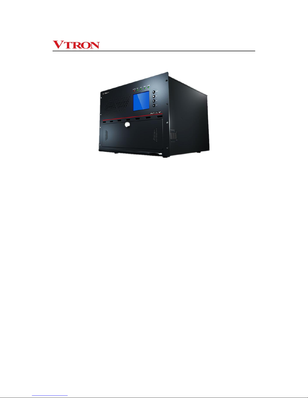
Digicom AP Series
Multi-screen Processor
V2.2
VTRON
http :// www.vtron.com
E-Mail: info @ vtron.com
All rights reserved
Page 2
User manual for Digicom AP series multi-screen processor
- -
i
This manual is the copyright property of VTRON. Without a prior written approval from
VTRON, no part of the text or graphics in this manual shall be copied illegally or distributed
to any third party in any manner.
This manual is subject to change due to technical upgrading without prior notice.
Digicom and VTRON are the trademarks of VTRON. Win7 is the trademark or registered
trademark of Microsoft in the USA and/or other countries (regions). Other product names
and company names mentioned in this document may be the trademarks of their respective
owners.
Note
This manual is designed for the introduction to Digicom AP series multi-screen processor
developed by VTRON. The specific configurations and functions of the product shall be in
accordance with the purchase contracts signed with the customer. The functions and display interface
of the product you order might differ from those in this manual. This is due to the difference in
configuration between the one you purchased and the one introduced in this manual.
Statement
Products as introduced in this manual are Class A products that may cause radio interferences in
living condition. Practical measures should be taken when necessary.
Page 3
User manual for Digicom AP series multi-screen processor
- -
ii
Please read carefully and make sure to comply with the following terms and
conditions before operating VTRON Digicom AP series multi-screen processor:
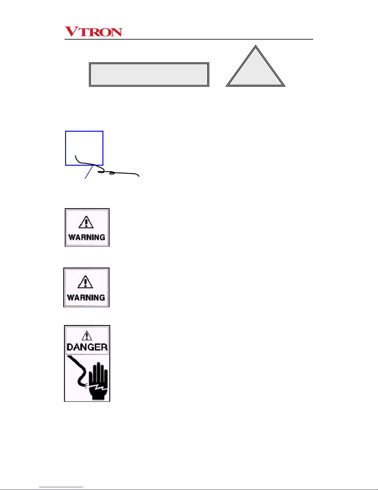
Ensure proper grounding (grounded as indicated
in the figure)
This product must be properly grounded to avoid dangers to
personal safety or any other harmful effects. Improper
grounding may cause severe system failure, unstable or
unreliable system operation, or even unrecoverable
breakdown of the equipment.
Illegal change to the original design is
prohibited
Any adding or deletion to any mechanical part or electric
circuit of this product is prohibited. Otherwise, VTRON will
not assume any liability for the results thus caused.
Prohibit the illegal installation of software
VTRON Digicom multi-screen processor is dedicated
image controlling device, and shall not be used for other
purposes. The customer shall consult VTRON or the
designated agent for the installation of their own
components. Otherwise VTRON will not assume any
liability for the results thus caused.
Be sure to cut off the power supply
Be sure to cut off the system power before conducting the
following operations.
A. Removal or reinstallation of any parts of the
product (except for the hot-pluggable parts)
B. Disconnection or reconnection of any electric
connector or other connectors of this product
Safety Precautions
!
Grounding wire
(connected to ground)
●
Page 4
User manual for Digicom AP series multi-screen processor
- -
iii
Keep away from corrosive chemical gas or agent
Corrosive chemical gas or agent will damage the
mechanical parts and electric circuits of the products and
directly affect its service life. Avoid cleaning the appearance
and inside of the product with highly volatile solvent, such
as gasoline, thinner, acetone, etc.
Keep away from inflammable and explosive materials
The product safety and personal safety cannot be ensured
in the environment with inflammable and explosive
materials.
Keep away from equipment with strong
electromagnetic interference
The performance and stability of this product will be
affected in an environment with strong electromagnetic
interference.
Disconnecting device of grid power
This product uses coupler or power connector as the
disconnecting device. Make sure that the connector or
coupler is easily accessible, so that the grid power can be
disconnected at dangerous time.
Note
The equipment adopts replaceable battery. If wrong
battery model is used, there exists the risk of explosion. Be
sure to use the standard battery components provided by
VTRON for replacement.
Dispose of the used battery according to the relevant
instructions. For the disposal methods of the used battery,
please consult the local environment protection
department.
Page 5

User manual for Digicom AP series multi-screen processor
- -
iv
Contents
1. Overview .............................................................................................................................1
1.1 About the Digicom AP series multi-screen processor ................................................2
1.2 Features of Digicom AP series multi-screen processor .............................................2
1.3 Naming rules of Digicom AP series processor ...........................................................5
2 Hardware introduction .......................................................................................................6
2.1 Technical specifications .............................................................................................6
2.2 Panel introduction .......................................................................................................8
2.2.1 Panel of AP2000 processor ................................................................................... 8
2.2.2 Panel of AP5000 processor ................................................................................. 10
3. Hardware installation ......................................................................................................13
3.1 Enclosure installation ...............................................................................................13
3.2 Connection to the user’s network .............................................................................13
3.3 Connection of display equipment .............................................................................14
3.4 Connection to signal source .....................................................................................14
3.5 Connection of network cable ....................................................................................15
3.6 Connection of power cable .......................................................................................15
3.7 System grounding .....................................................................................................15
4 Software.............................................................................................................................16
4.1 Standard software ....................................................................................................16
4.2 Display wall application administration software: VWAS (optional) .........................17
5. Daily maintenance ...........................................................................................................18
5.1 Environment and cleaning ........................................................................................18
5.2 Routine inspection ....................................................................................................19
5.3 Troubleshooting ........................................................................................................19
6 Contact Us .........................................................................................................................24
Page 6

User manual for Digicom AP series multi-screen processor
- -
1
1. Overview
Multi-screen processor, also called multi-screen display controller, is a dedicated image
processing device based on certain operating system platform and offering multi-screen
driving function to perform remote display and control on various types of signals through
different modes. Generally speaking, it is a computer system with power functions.
However, different from the ordinary computer system, it is also a powerful image server
system.
When there is no multi-screen processor, the signals from the signal sources can still be
directly input to the digital display wall for display, but the display capacity of the digital
display wall system is completely subject to the display capacity of the display wall. The
application of the multi-screen processor can realize the processing and conversion of
signals before they are input to the digital display wall, thus greatly expanding the display
functions, application scopes and application methods of the display wall. It is a component
of great significance in the digital display wall system.
Page 7
User manual for Digicom AP series multi-screen processor
- -
2
1.1 About the Digicom AP series multi-screen processor
The Digicom AP multi-screen processor is a universal processor developed, designed and
produced by VTRON, featuring extensive applications, power functions and high price
performance ratio. In addition to the hardware for ordinary computer, it is configured with
professional graphics card and renders high performance in image processing. It can
provide several types of drive signals of high resolution for each display channel and
generate desktop of high resolution. Besides, it is equipped with RGB, Video, HDMI, YPbPr
and SDI cards to achieve the acquisition, exchange, zooming and superimposition of the
RGB, Video, HDMI, YPbPr and SDI signals.
The Digicom AP series multi-screen processor adopts the Windows operating system and
the second generation PCI Express non-block digital bus exchange technology, offering a
large bandwidth capacity, high performance, high quality assurance and high reliability. It is
especially suitable for the applications of small digital display wall system of super high
resolution.
1.2 Features of Digicom AP series multi-screen processor
The Digicom AP multi-screen processor is a universal processor with extensive
applications, powerful functions and high price performance ratio. It is especially suitable
for the display wall system of super high resolution. The processor adopts the Windows
operating system and offers a large spread Windows image display environment of high
resolution.
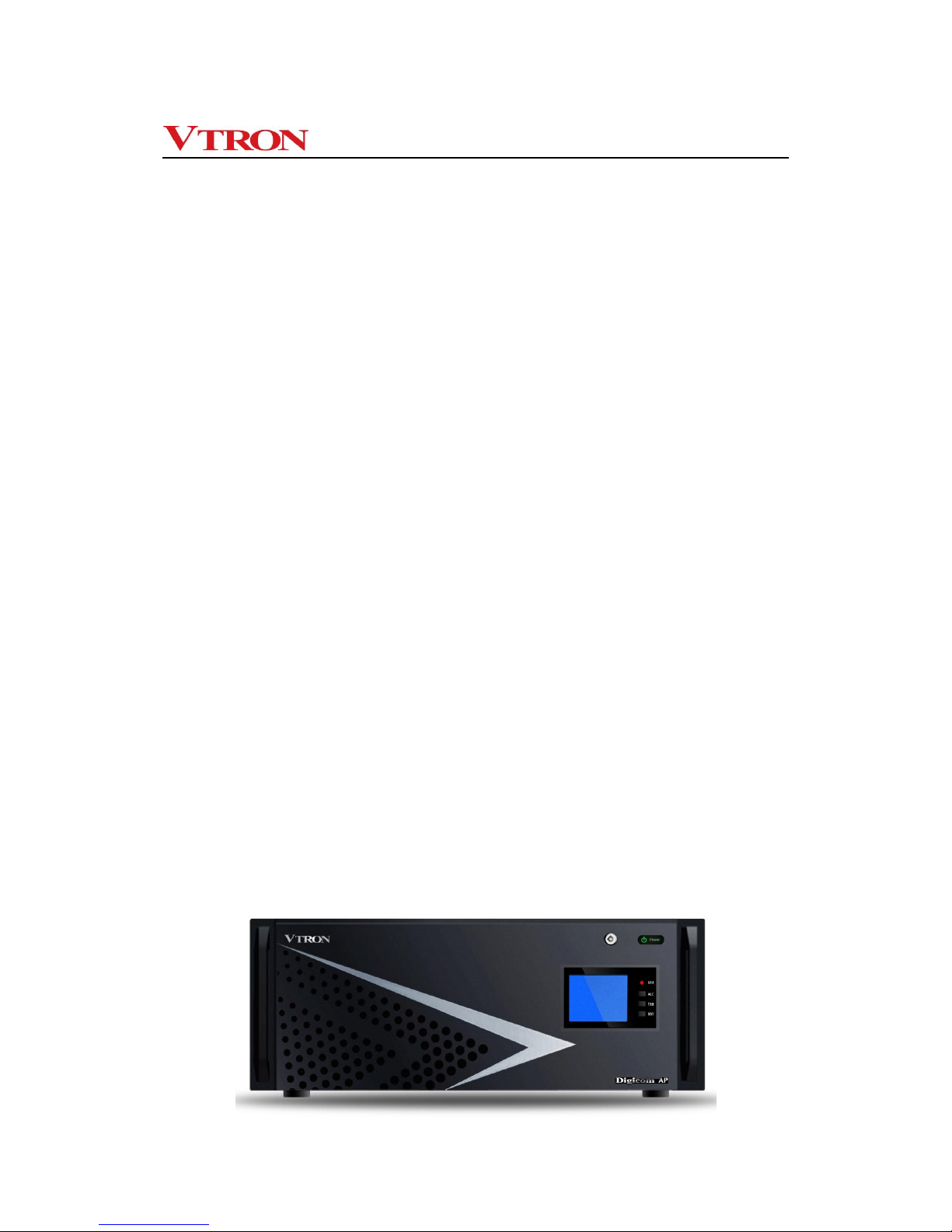
Appearance of Digicom AP2000 series multi-screen processor:
Page 8
User manual for Digicom AP series multi-screen processor
- -
3
Appearance of Digicom AP5000 series multi-screen processor:
Features
PCI Express Digital Bus Switching Technology
Digicom AP series multi-screen processor is a versatile integrated multi-screen image
processor that relies on cutting-edge PCI Express non-block digital bus switching
technology to realize scalability and various display effects. It meets any configuration and
application requirements of small- and medium-sized display wall systems (less than 30
display cubes).
Leading the new era of “super high resolution display”
Digicom AP series multi-screen processor is equipped with industry-leading high-end
graphics processing card, high performance CPU, and Windows 7 OS (or Windows 8 OS;
depending on system configuration), and therefore can run various applications and
support multiple tasks to be operated and applied on the Windows-based super high
resolution desktop. Meanwhile, it offers automatic full-screen smooth display. Various
signal windows can be clearly smoothly displayed on the desktop, and combined, zoomed
in/out, superposed, and roamed.
Various powerful APLink input cards, realizing fast access and display of
various signals
APLink input cards rely on VTRON proprietary transmission & display technology to ensure
they can transmit and display input signals in full frame manner. They can display various
Page 9

User manual for Digicom AP series multi-screen processor
- -
4
signals perfectly, including composite video (camera or DVD signal), computer signal (VGA
or DVI signal), HD digital signal (HDMI, HD component YPbPr, high-resolution DVI or highresolution SDI signal).
① APLink DVI input card supports unidirectional and bidirectional-link digital DVI signal or
analog VGA signal display; Refresh rate is as high as 60 frame/s.
② APLink Video input card supports composite video input over the NTSC/PAL standard.
All video input signals can be displayed at the same time through windowing.
③ APLink HDMI input card supports Full HD 1080p & 4Kdigital video signal input over the
standard protection protocol HDCP.
④ APLink YPbPr input card supports HD component (720P, 1080i, 1080p) video signal
input; While working with various types of VTRON IP encoder devices, it can collect
distributed signals from long distances and display quality images.
⑤ APLink SDI input card supports SDI signal input over the SD, HD or 3G standard. All
SDI input signals can be displayed at the same time through windowing.
Integrating with IP video signal access function and supporting flexible access
of computer signals
Within the same structure, the processor supports leading technologies of IP video signals,
and such encoding formats as H.264, MPEG4, MPEG2, and MJPEG as well as RTSP. The
processor supports TCP/IP as well, and uses VLinkExpress to connect to the Internet,
allowing multiple online terminal windows to be roamed and zoomed in/out on the high
resolution desk.
Stable and reliable system
AP5000 series system is integrated with the design of reliability and equipped with fan of
the heat exchange system, and heat exchange hard disk to ensure 24 × 7 hours
uninterrupted and reliable running of the system.
Intelligent system management
The air outlet and inlet and core parts of cards are designed to meet requirement of realtime intelligent temperature control, as well as to have high-temperature alarm and overtemperature protection function. Through these designs, you can query state information,
including state of the BIOS, CPU, memory, GPU, and system running time. An LCD display
is also delivered to realize visualized monitor of system running state.
Page 10

User manual for Digicom AP series multi-screen processor
- -
5
1.3 Naming rules of Digicom AP series processor
Digicom AP x □ y z
由“0~9”表示,可与末位“z”代表数字联合表示“单机箱”或“扩展
机箱”可驱动的拼接墙规模数量,同时满足认证报备型号使用;
固定由“0”表示;
由“1-9”组成,表示面对不同应用的细分市场提供可满足专用型号的
处理器产品,同时满足认证报备型号使用;
由“0~9”或“空位”表示,代表数字时可与前一位“y”联合表示“单
机箱”或“扩展机箱”驱动的拼接墙规模数量,当为“空位”时代表另
一族产品,同时满足认证报备型号使用;
It is filled with “0~9” or “blank”. When it is filled with digit, it, in conjunction with the “y”
before it, indicates the number of the combined screens driven by the “single
enclosure” or “expanded enclosure”. When it is “blank”, it indicates another family of
products, and is reserved for the model applying for certification.
It is filled with “0~9” and, in conjunction with the “z” after it, the number of the
combined screens driven by the “single enclosure” or “expanded enclosure”. It can
also be reserved for the model applying for certification.
It is filled with 0.
It is filled with “1~9”, indicating the processor model that can meet the special
application of the market segments. It can also be reserved for the model applying for
certification.
Page 11

User manual for Digicom AP series multi-screen processor
- -
6
2 Hardware introduction
2.1 Technical specifications
Digicom AP2000
Multi-screen Processor
Digicom AP5000
Multi-screen Processor
CPU
Intel multi-core CPU
Intel multi-core CPU
Internal memory
4GB (standard configuration)
8GB (standard configuration)
Disk drive
Dual HD: 1TB×2(SATA II)
DVD-ROM (SATAII)
Ethernet interface
Dual gigabit RJ45 network port, 100/1000M self-adaptive
Slot scalability
A maximum of 6 PCI Express 3.0 slots
A maximum of 17 PCI Express 2.0 slots
External input port
PS/2 interfaces for mouse and keyboard;
4 USB interfaces
Graphics card
Number of outputs: 12 at most
Number of outputs: 28 at most
Output resolution: 1024 × 768@60Hz~1920 × 1080@60Hz
2GB DDR5 Graphics memory
Color depth: 16-bit or 32-bit
Output interface: Mini-DisplayPort to DVI-D
RGB input
(expandable)
Number of inputs: 20 at most
Number of inputs: 32 at most
Input format: DRGB: 640 × 480@60 Hz~1920*1200@60 Hz (signal bandwidth
<170Mhz)
ARGB: 640 × 480@60 Hz~1920*1200@60 Hz (signal bandwidth <170Mhz)
Color depth: 16-bit or 32-bit
Input interface: DMS-59
Video input
(expandable)
Number of inputs: 40 at most
Number of inputs: 64 at most
Input format: NTSC, PAL
input interface: BNC
HDMI input
(expandable)
Number of inputs: 20 at most
Number of inputs: 32 at most
Signal standard: HDMI V1.3&V1.4a; HDCP supported
Video input : 640x480@60Hz~1920x1080@60Hz; 3840x2160@30Hz; FullHD1080P
Audio input: 44.1KHz, 48KHz signal in dual-channel PCM format (16 bit)
Input interface: HDMI
Color depth: 16 bit or 32 bit
YPbPr input
(expandable)
Number of inputs: 10 at most
Number of inputs: 32 at most
Input resolution: 1080P@60, 1080P@50, 1080i@60, 1080i@50, 720P@60, and
720P@50
Input interface: component interface
(1 DB interface is converted to components of 2 channels)
Page 12

User manual for Digicom AP series multi-screen processor
- -
7
SDI input (expandable)
Number of inputs: 20 at most
Number of inputs: 32 at most
Signal standard supported: SD-SDI, HD-SDI or 3G-SDI
Input resolution: 1080P@60, 1080P@30, 1080i@60, 1080i@50, 720P@60,
720P@50, 576i@50, 480i@60
IP video input (standard
configuration)
The display wall can display a
maximum of 8-channel 1080P
video, 32-channel D1 video, or 32-
channel CIF video.
The display wall can display a maximum of
8-channel 1080P video, 32-channel D1
video, or 32-channel CIF video.
Support standard H264, MPEG4, MPEG2, and MJPEG encoding formats.
Note: Devices that are not contained in the standard signal source list support
secondary development;
Users should offer secondary development protocols (SDK) of IP videos that are
used on WINDOW-based brand platforms.
IP encoder
(expandable)
While working with various types of VTRON IP encoder devices, it can collect
distributed signals from long distances and display quality images.
Network computer
signal access
(expandable)
Up to 8-channel VLink signals can be displayed simultaneously.
Signal window
superimposition
Support free combination, zooming in/out, superimposition, and roaming display
of signal windows.
Intelligent surveillance
Real-time monitor system running states, including chassis temperature, CPU
temperature, GPU temperature, fan speed, CPU usage, and memory usage.
System power supply
1+1 redundant power(optional )
100-240V AC 50/60 Hz 2.0A
1+1 redundant power, hot-swappable
100V-240VAC 50/60 Hz 8-6A
Rated power
≤ 300W
≤ 600W
Chassis dimension
Black, 19" standard rack-mount
method; height: 4U
W × H × D = 482 mm × 177 mm ×
480 mm
Black, 19" standard rack-mount method;
single-chassis height: 8U
W × H × D = 431 × 354.3 × 501.7
(excluding the front-panel handle)
Chassis fan
Fan standby, replaceable by means of hot swap
Noise
< 45 dB
< 45 dB
Weight
≤ 20 Kg
≤ 40 Kg
Operating environment
Operating temperature: 0°C~40°C
Relative humidity: 20%~80% (non-condensing)
Storage environment (in
packed manner)
Storage temperature: –40°C-70°C
Relative humidity: 0%~95% (non-condensing)
OS
Windows 7/Windows 8
professional; 64-bit
Standard configuration: Windows 8
professional; 64-bit
Application software of
the processor
Large-screen control software: VTRON VWAS Standard (additional payment)
remote access control software: VLinkExpress (optional)
Product certification
CCC, CE, CB, RoHS
CCC, CE, CB, RoHS
Page 13

User manual for Digicom AP series multi-screen processor
- -
8
Note:
System power supply:Redundant power supply function is optional for the AP2000
processor. The following figures of the AP2000 processor with redundant power module is
just for description and reference only. The actual appearance may vary due to your
different purchase contract.
This manual is subject to changes without notice.
2.2 Panel introduction
Note: The figure below is for illustration only. For the specific product outline and
configuration, please refer to the customer order.
2.2.1 Panel of AP2000 processor
The Digicom AP series multi-screen processor adopts IPC 4U industry back plate
enclosure and supports up to 6 PCIE slots.
The following table describes the indicators and function keys.
Indicator/key
Function
STU indicator
Status indicator; green: normal state; red: abnormal state.
ALC key
Alarm clearance
TAB key
Page switching
RST key
System reset
Power status indicator
Monitor display
Handle
Status indicator
Function key
Page 14

User manual for Digicom AP series multi-screen processor
- -
9
Back panel:
Note: The above figure is for illustration only. For the specific product outline and
configuration, please refer to the customer order.
Power
module
PS/2
keyboar
d/mouse
port
USB port
Video /SDI
signal
input port
Signal
output port
RGB
signal
input port
RJ45 network port
YPbPr
signal
input
HDMI
signal
input port
Page 15

User manual for Digicom AP series multi-screen processor
- -
10
2.2.2 Panel of AP5000 processor
Front panel of AP5000 series processor
The following describes the LCD display, LED indicators, and function keys:
1. LCD Display
The LCD backlight supports automatic protection. If the processor is not operated
within a stipulated period and no abnormality alarm is reported, the LCD backlight will be
automatically shut down. A key operation will trigger the LCD backlight on and set the LCD
to monitor state. If an abnormality alarm is reported, the LCD backlight will light up as well.
Following information will be shown on the LCD display:
Date/time: Current date and time; modifiable through function keys. The clock will
be automatically stored when the processor is powered off. You do not need to set
the time again upon startup each time.
Fan: The fans of three channels are monitored and they are named “FAN1”,
“FAN2”, and “FAN3” on the LCD display. Under the fan names is displayed the
rotary speed of the fans in a circular manner (unit: rpm). If a fan is faulty, its name
will turn white.
LCD display
LED indicator
Function keys
Heat dissipation
hole
Page 16

User manual for Digicom AP series multi-screen processor
- -
11
Power supply: On the LCD display, the modules are named by PWR+Number
(such as “PWR1”, “PWR2”, and “PWR3”). When they are working normally, their
working state is “OK”. If a fault occurs, their state changes to “NG” which is shown
in white.
Temperature: Three groups of temperature probes are equipped in the chassis
and they are located at the air inlet and air outlet, and inside the chassis body. On
the LCD display, they are named “T1”, “T2” and “T3” respectively. The three
groups of temperature probes are responsible for detecting ventilation state of the
while machine. If an abnormality occurs, corresponding probe name will turn white
to alarm users. Above the probe names, their detecting temperature (unit: °C) is
shown in a circular manner.
Over-temperature alarm: This parameter is set to 80°C by default upon
initialization and it can be modified through special software over the RS232 port.
If a monitored object generates an alarm, the detecting temperature is the alarm
temperature and will not change. Meanwhile, the beeper sounds and
corresponding LED indicator blinks.
2. LED Indicators
On the front panel, there are 5 LED indicators they are “POWER”, “FAN”, “HDD”,
“TEMP”, and “ALARM” respectively. Except for the red HDD indicator, other indicators have
both green and red colors.
LED
Function
Normal State
Abnormal State
POWER
Indicating the operating
state of the computer’s
power supply
Green
Red; blinking
FAN
Indicating the operating
state of the fan in the
chassis
Green
Red; blinking
HDD
Indicating read/write
state of the hard disk
Red; blinking
–
TEMP
Indicating the
temperature monitor
state in the chassis
Green
Red; blinking
ALARM
Indicating the alarm
monitor state
Green
Red; blinking
3. Function Keys
On the front panel, there are also 4 function keys and they are “MODE”, “SET”, “TAB”,
and “ALC” respectively.
Page 17

User manual for Digicom AP series multi-screen processor
- -
12
Key
Function
MODE
Indicating the clock calibration mode; when this mode is enabled,
time calibration can be accurate to minute.
SET
Used for time calibration
TAB
Page switching
ALC
Alarm clearance
Real Panel of AP5000 Series Processor
Real panel of AP5000 series processor
Video/SDI signal
input interface
Signal output
interface
YPbPr signal
input
interface
RGB signal
input
interface
HDMI signal
input interface
Redundant
power
module
Power input
RGB signal
input
interface
Page 18

User manual for Digicom AP series multi-screen processor
- -
13
3. Hardware installation
Note: The system installation must be performed by persons duly trained and qualified.
The Digicom AP series multi-screen processor is delivered to the user as a complete
system. All the hardware resources in the processor have been installed strictly according
to the installation process in the plant and passed the relevant tests (e.g., high temperature
test, aging test, etc.).You only need to connect the multi-screen signal processor to the
external equipment onsite.
Please check the items according to the packing list upon unpacking. If there is any loss or
damage, call the supplier. The packing list is in the packing box.
3.1 Enclosure installation
The Digicom AP series multi-screen processor adopts standard industry control enclosure
and modular design to facilitate the installation of the processor into standard cabinet in
certain applications.
The Digicom AP series multi-screen processor can be installed on the dedicated mounting
rack near the display wall or in the dedicated cabinet. However, please note that when the
multi-screen processor is installed in the cabinet, the ventilation and heat dissipation of the
cabinet must be ensured. Although the processor has strong heat dissipation capability, if
the hot air in the cabinet is maintained for a long time, the ambient temperature will be
gradually increased, which will consequently affect the operating performance and life of
the equipment.
The power socket of the Digicom AP series multi-screen processor is located at the lower
left side of the back panel. When connecting the equipment power socket and the 220V
plugboard, please use the cable delivered together with the equipment.Incompliant power
cable will affect the power supply, and performance stability of the equipment.In addition, to
ensure the stability of the power supply to the multi-screen processor, the processor power
socket must be connected to independent power plugboard. Do not share power plugboard
with other equipment.
3.2 Connection to the user’s network
The Digicom AP series multi-screen processor can work in the network. Therefore, in
Page 19

User manual for Digicom AP series multi-screen processor
- -
14
actual application, the processor will be connected to the network through the hub. On the
back panel of the multi-screen processor, there are two dedicated network ports for
connecting the processor to the hub.
3.3 Connection of display equipment
Connect the output interface of the Digicom AP series multi-screen processor to the
corresponding input interface of the display equipment with the signal cable delivered
together with the product.
Note:
Digital signals have strict requirement on signal transmission, therefore, you are advised to
use the signal cable provided by VTRON.Please consult VTRON or the agent if you have to
use your own signal cable.
3.4 Connection to signal source
Connect the RGB signal input channel of the Digicom AP series multi-screen processor to
the output channel of the RGB signal source with the RGB signal cable delivered together
with the product; connect the video input channel of the processor to the output channel of
the video signal source with the video signal cable; connect the HDMI input channel of the
processor to the output channel of the HDMI signal source with the HDMI signal cable ;
connect the YPbPr input channel of the processor to the output channel of the YPbPr signal
source with the YPbPr signal cable ; connect the SDI input channel of the processor to the
output channel of the SDI signal source with the SDI signal cable ;connect the processor to
the IP video signal source through the exchange with the network cable (note: signal
source of the same network segment or different segment are acceptable).
The RGB signal source onsite generally refers to the operating PC, professional
workstation or the matrix connected to such equipment. The HDMI signal source onsite
generally refers to the operating PC, video player or the matrix connected to such
equipment. The YPbPr signal source onsite generally refers to the YPbPr output of video
player. The SDI signal source onsite generally refers to camera and matrix connected to
the SDI interface. There are many types of video signal source, including common video
play equipment and camera. Since there are many video input channels, be sure to
connect the correct channel to the corresponding signal source. Only in this way can you
correctly call the video signal source in the applications.
Page 20

User manual for Digicom AP series multi-screen processor
- -
15
3.5 Connection of network cable
The Digicom AP series multi-screen processor can work in the network. You can also
control the processor through network. In actual application, you need to connect the multi-
screen processor to the network through exchange, that is, to connect the exchange to the
network interface with network cable. The network interfaces to be connected depend on
the onsite network availability.
3.6 Connection of power cable
When connecting the equipment power socket and the plugboard, please use the cable
delivered together with the equipment. Incompliant power cable will affect the power supply,
performance stability and safety of the equipment. In addition, to ensure the stability of the
power supply to the multi-screen processor, the processor power socket must be
connected to independent power plugboard (220V10A standard plugboard recommended).
Do not share power plugboard with other equipment.
3.7 System grounding
To ensure the safety and stability of the equipment as well as the safety of the operator, the
equipment must be properly and securely grounded. That is, the grounding terminal on the
enclosure must be connected to the dedicated grounding system with dedicated grounding
conductor through proper method.
Note: to ensure the safe operation and the normal working of the system, the electric
grounding of the electronic product is compulsory. Improper grounding will severely affect
the reliability and stability of the system and cause negative impact on the signal quality.
Therefore, when installing the Digicom AP series multi-screen processor, you need to fully
consider the grounding measures of the whole system environment, including whether the
power supply has the grounding measure (e.g., adopting the certified three-core power
cable and power socket). Besides, when installing the Digicom AP multi-screen processor
in the high-rise building, the equipment shall be connected to the true earth through the
dedicated safe grounding system and kept away from the SPD grounding system of the
building. Improper system grounding will have large negative effect on the signal
transmission, which will result in the imaging interferences that cannot be removed through
debugging. For details, please consult VTRON. Please strictly comply with the relevant
instructions and maintain proper grounding during the use of the equipment.
Page 21

User manual for Digicom AP series multi-screen processor
- -
16
4 Software
4.1 Standard software
The Digicom AP series multi-screen processor is configured with all the standard software
upon delivery, including Windows operating system, corresponding hardware drive and
standard application software You can use the processor immediately after you have the
relevant peripherals installed.
Note:
To ensure the normal operation of the multi-screen processor, be sure to install
and use the original software (including but not limited to the Windows operating
system).
The multi-screen processor is a dedicated image processing device. If you need to
install other application software or programs in the processor system, please
consult VTRON or its agent to obtain the relevant technical support.
Page 22

User manual for Digicom AP series multi-screen processor
- -
17
4.2 Display wall application administration software: VWAS (optional)
VWAS (VTRON Display Wall Administration System) is the application administration
system developed by VTRON for the development, design and production of the display
wall system and its multi-screen processing system. It is mainly used to provide control and
management on hardware resources in the display wall system (e.g., the display unit, multi-
screen processor and other peripherals), so as to realize the management and control on
the signal windows and application windows shown on the display wall. The VWAS can
make full use of the network distributed software system, support simultaneous connection
and operation of several clients, provide simple, friendly and customizable man-machine
interface, thus realizing quick and convenient control and simple operation on the combined
display wall, and completely eliminating the defect of traditional display wall, i.e., complex
operation.
Introduction to main functions of VWAS
To control the multi-screen processor, and operate the relevant windows and
applications on the multi-screen processor (the multi-screen processor windows
include the application window, video window, RGB window , Vlink window, HDMI
window, YPbPr window and IPVideo window);
To realize the orderly batch operation on the multi-screen processor window and multi-
screen processor applications through the preset mode and scheme (you can
customize the operation modes and schemes according to the actual situations);
To realize the joint control on the relevant peripherals, such as the matrix, camera,
multi-screen equipment, and image splitter;
To provide functional module and equipment expansion and support the development
of the third party;
To provide software registration and hierarchical control of users (users that log on the
system in different roles or different levels have different functions and authorities);
Page 23

User manual for Digicom AP series multi-screen processor
- -
18
5. Daily maintenance
5.1 Environment and cleaning
Note: The equipment does not need any internal adjustment, and there is no user
serviceable component in the equipment. To replace any part or repair the equipment,
please contact the local authorized service center. We are prepared to provide prompt
service to you and help you solve the relevant problems.
Daily inspection and maintenance
1) The operating environment of the equipment shall be free of dust, dry and have
good ventilation.
2) Operating temperature: 0 ºC - 40 ºC Relative humidity: 20% - 80%, no condensing
3) Keep the equipment clean, and avoid using any rough or abrasive cleaning agent.
4) Do not place anything in and above the ventilation hole and ventilation slot. Avoid
spraying any liquid or chemicals on or near the equipment.
Equipment cleaning
1) Be sure to disconnect the power socket before cleaning the equipment.
2) Avoid using any liquid or spray cleaning agent when cleaning the inside or outside
of the equipment.
3) Avoid using the corrosive solution (e.g., chemical thinner, acetone, gasoline or
other abrasive cleaning agent), because such solution will damage the equipment
appearance.
Page 24

User manual for Digicom AP series multi-screen processor
- -
19
5.2 Routine inspection
1) Check if the system is properly grounded each month.
2) Check if the connecting wire and power cable are broken or worn out, if the
connector and plug-ins are loose, eroded and oxidized each month.
3) If the system is not frequently used, turn on and run it for 1 to 2 hours each week.
In damp seasons, the frequency shall be above once a day.
5.3 Troubleshooting
1. No power supply when the equipment power switch is turned on
Possible cause
1) The general power switch has not been turned on;
2) The input power does not meet the relevant requirements;
3) The power module switch is in “OFF” position.
4) Other unknown reason
Troubleshooting method
1) Check if the general power for the multi-screen processor has been turned on. If not,
turn on the general power and then press the power switch of the multi-screen
processor.
2) Check if the input power meets the equipment power requirements.
Note: Make sure that the input power of the multi-screen processor meets the
equipment power requirements. Otherwise, the equipment will be damaged, and the
operator safety will be endangered.
3) Turn the power switch of the power module to “ON” position, and then press the power
switch of the multi-screen processor.
4) If the problem still persists, please contact VTRON or the agent. We will give response
to you as soon as possible.
2. The multi-screen processor has normal power input, but there is no display on the
display terminal when the power switch is pressed, and the processor has no alarm
message.
Possible cause
Page 25

User manual for Digicom AP series multi-screen processor
- -
20
1) The display terminal equipment has not been started;
2) The signal cable of the multi-screen processor is in poor connection or has not been
connected;
3) The multi-screen processor HD is locked;
4) The Windows operating system has not been started;
5) Other unknown reason
Troubleshooting method
1) Check if the power supply of the display terminal equipment has been turned on;
2) Check if the output signal cable of the multi-screen processor is properly connected to
the display terminal;
3) If the problem still persists, please contact VTRON or the agent. We will give response
to you as soon as possible.
3. Keyboard/mouse fails
Possible cause
1) Non-original keyboard/mouse is used;
2) The keyboard/mouse extension cable is faulty (when the extension cable is used);
3) The keyboard/mouse works abnormally;
4) Other unknown reason
Troubleshooting method
1) Use the original keyboard/mouse;
2) Check if the keyboard/mouse extension cable is properly connected or damaged.
You can disconnect the extension cable and directly connect the keyboard/mouse to
the processor to check if the keyboard/mouse works normally.
3) Replace it with the keyboard/mouse of the same model, and contact VTRON or its
agent;
4) If the problem still persists, please contact VTRON or the agent. We will give response
to you as soon as possible.
4. Abnormal image color display
Possible cause
1) The signal cable of the multi-screen processor is in poor connection or the system
grounding is poor.
2) the signal output quality problem of the signal output equipment;
3) The signal source parameters are not correctly adjusted;
Page 26

User manual for Digicom AP series multi-screen processor
- -
21
4) The display terminal (e.g., display wall) problem;
5) Other unknown reason
Troubleshooting method
1) Check if the signal cable of the multi-screen processor is properly connected, and if the
grounding is normal.
Besides, if the non-original signal cable or other poor quality cable is used, the image
display will be adversely affected. Please check and correct such undesired use.
2) Check if the signal output equipment operates normally.You can use a normal monitor
to display the signal contents separately, so as to judge if the signal output equipment
is faulty or not.
3) Readjust the signal source parameters. Because the display effect of the signal source
on the display wall is quite subjective, the adjustment of the display effect is time
consuming, and skillful operator is needed.
To save time, you can use the user parameter scheme to call the used parameters.
4) Check the display wall equipment according to the instructions for the display terminal
equipment. You can also bypass the multi-screen processor to directly connect the
signal to the display terminal to judge if it is the problem of the processor output.
5) If the problem still persists, please contact VTRON or the agent. We will give response
to you as soon as possible.
5. There is no signal display on the window, or the window is in blue screen or other
pure color background.
Possible cause
1) Poor cable connection
2) Incorrect selection of the input channel for the RGB signal source or VIDEO signal
source;
3) The display terminal problem;
4) Other unknown reason
Troubleshooting method
1) Check if the cable connection is reliable;
If the Vlink application window has no display, check if the network communication
between the multi-screen processor and the remote PC is normal;
2) Check the physical connection of the selected channel;
3) Check if it is the display wall problem according to the above method;
Page 27

User manual for Digicom AP series multi-screen processor
- -
22
4) Close the window and restart the program.
Run the program again after restarting the Windows OS.
If the problem still persists, please contact VTRON or the agent. We will give response
to you as soon as possible.
Page 28

User manual for Digicom AP series multi-screen processor
- -
23
6. Slack display of the Vlink window
Possible cause
1) The network speed does not meet the requirement. When the image refresh rate of the
Vlink window reaches 10 frames/s, obvious hold-up appears in the image display.
2) Too many windows are opened by the multi-screen processor;
3) Other unknown reason
Troubleshooting method
1) Check the network communication status, and replace the exchange when necessary.
2) Close the windows not in use (especially the RGB windows that are not needed for the
moment).
3) Please contact VTRON or the agent. We will give response to you as soon as
possible.
7. Image flashing
Possible cause
1) Poor cable connection and poor grounding
2) the image refresh rate of the multi-screen processor is too low
Troubleshooting method
1) Check the cable connection and grounding status of the hardware system;
2) Reinstall the drive and select proper refresh rate;
3) Please contact VTRON or the agent. We will give response to you as soon as
possible.
Page 29

User manual for Digicom AP series multi-screen processor
- -
24
6 Contact Us
About after sales service matters please contact after sales department of VTRON
GROUP CO.,LTD.
VTRON GROUP CO.,LTD.
No. 233 Kezhu Road, Guangzhou Hi-Tech Industrial Development Zone
(Guangzhou Science City),
Guangzhou 510670, China
Tel: +86-20-8390-8888
Fax: +86-20-8390-3591
Email: INFO@VTRON.COM
VTRON GROUP CO.,LTD. (Hong Kong)
Unit 1608-09, 16/F, Tower 1, 193 Prince Edward Road West, Grand Century
Place Mongkok, Kowloon Hong Kong
Tel: +852-2264-3688
Fax: +852-2264-3833
Email: INFO@VTRON.COM
VTRON Hong Kong Technical Support Centre
Unit 1225, 12/F, Corporation Park,11 On Lai Street,
Shatin, New Territories, Hong Kong
Tel: +852-2613-9708
Fax: +852-2613-9277
Email: INFO@VTRON.COM
VTRON GROUP CO.,LTD. (Malaysia Rep Office)
Unit 29-6 Block E1, Dataran Prima Business Centre, Jalan PJU 1/42, Petaling Jaya
47301, Selangor Darul Ehsan, Malaysia.
Tel: +603-7880-0338
Fax: +603-7887-0304
 Loading...