

Page 1

User Manual
Visionpro® C Series Display Cube
V1.4
VTRON
http :// www.vtron.com
E-Mail: info @ vtron.com
All rights reserved
Page 2
User Manual Visionpro
®
C Series Display Cube
- -
i
This manual is the copyright property of VTRON. Without the prior written consent of
VTRON, no part of the text or graphics in this manual shall be copied or distributed to
any party in any manner.
This product may allow you to use third party software or upload/download works
belonging to a third party, including articles, images, video, or software, but VTRON
does not own or provide such works. Your use of the aforementioned works belonging to
a third party means that you agree to use such works without infringing or breaching the
rights of the third party, and VTRON does not assume any liability for your use thereof.
VTRON and Visionpro® are the global registered trademarks of VTRON Company.
This manual is subject to change due to technical upgrades without prior notice.
Note: Images in this manual are for description and reference only. For actuality and
details, please refer to the product you received.
Note:
Texts and graphics in this manual are for providing an introduction to the
Visionpro® series display cubes offered by VTRON only. Product configurations
and functions will be in accordance with the purchase contracts signed by the
customer. The functions and display interface of the product you order might differ
from those in this manual. This is due to the difference in configuration between
the one you purchased and the one introduced in this manual.
Statement:
Products as introduced in this manual are Class B products that may cause
radio interference in domestic environment. Practical measures should be taken
when necessary.
Page 3
User Manual Visionpro
®
C Series Display Cube
- -
ii
Before operating Visionpro® series display cubes, please read and observe the
following safety precautions thoroughly.
Ensure proper grounding(grounded as indicated in
the figure)
The product should be grounded properly. Otherwise, a
series of problems will occur: serious system fault,
system instability and unreliability, and even the
paralysis to the whole system. Even worse, the safety of
users cannot be ensured.
Do not change the original design
Any addition to or deletion from any mechanical part
or electrical circuit in this product is prohibited.
VTRON will not assume any liability resulting
therefrom.
Do not install unauthorized software
The Visionpro® series display cube is a dedicated
device and must not be used for any other purpose.
Consult VTRON or a designated agent for the
installation of your own software. VTRON will not
assume any liability resulting therefrom.
Grounding (connected to earth)
●
Safety Precautions
!
Page 4
User Manual Visionpro
®
C Series Display Cube
- -
iii
Be sure to disconnect the power supply before
the following operations:
A. Removal or reinstallation of any part of the
product.
B. Disconnection or reconnection of any electrical
connector or other connector in this product.
Keep the display cube away from corrosive
chemical gas or agent
Corrosive chemical gases or agents will damage the
mechanical parts and electrical circuits of the product
and directly affect its lifetime. Avoid cleaning the
exterior or interior of the product with a highly
volatile solvent, such as gasoline, paint thinner,
acetone, etc.
Keep the display cube away from flammable
and explosive materials
Product safety and personal safety cannot be ensured
in an environment with flammable and explosive
materials.
Keep the display cube away from equipment
with strong electromagnetic interference.
Page 5

User Manual Visionpro
®
C Series Display Cube
- -
iv
Dangerous voltage inside.
May cause electric shock, burns, or death.
No user serviceable parts inside.
Only the dust screens and fuses are user serviceable. The
maintenance personnel must be properly trained;
otherwise, electric shock, UV radiation burns, contact
burns, serious injury, or irreparable damage to the
Visionpro® series display cube may be caused, and your
warranty will be invalidated.
Only the dust screens and fuses are user serviceable
The power must be disconnected before conducting such
operations. All the maintenance tasks must be carried out
by properly trained personnel.
The projection unit uses a professional-grade
ultra-bright LED light source. Do not replace the
LED with another LED light source, or the system
may be damaged.
Do not shut down the cooling fan of the Visionpro®
series display cube or block the surrounding air
circulation.
Page 6
User Manual Visionpro
®
C Series Display Cube
- -
v
Dust in the air and hot air may cause the hardware of the
Visionpro® series display cube to short-circuit. Do not
operate the cube in a dusty or high-temperature
environment.
A10 cm clearance must be maintained at the top of
the vertical top layer of the Visionpro® series display
cube for the air circulation of the fan.
Some screens are sensitive, and fingerprints on the screen
will affect their optical performance. So the Visionpro®
series display cube must be protected against any
touching or scratching.
Disconnecting device of grid power
This equipment uses a coupler or power connector as the
disconnecting device. Make sure that the connector or
coupler is easily accessible so that you can disconnect the
grid power in an emergency.
Page 7

User Manual Visionpro
®
C Series Display Cube
- -
vi
Content
1 DISPLAY CUBE OVERVIEW ................................................................................................................. 1
1.1 MAIN FEATURES ..................................................................................................................................... 3
1.2 APPEARANCE OF C SERIES DISPLAY CUBE ................................ ............................................................. 4
1.3 MAIN COMPONENTS OF C SERIES DISPLAY CUBE .................................................................................. 6
1.4 TECHNICAL SPECIFICATIONS OF C SERIES DISPLAY CUBE ..................................................................... 7
1.5 DIMENSIONS OF C SERIES DISPLAY CUBE .............................................................................................. 8
2 PROJECTOR OF C SERIES DISPLAY CUBE ................................................................................... 10
2.1 ENGINE OVERVIEW .............................................................................................................................. 10
2.2 INTERFACE BOX OVERVIEW ................................................................................................................. 12
2.2.1 Appearance of the Interface Box .................................................................................................. 12
2.2.2 Boards of VCL-3/VCL-3+ /VCL-3A Interface Box ..................................................................... 15
3NETWORK ENVIRONMENT FOR THE VIDEO WALL SYSTEM ................................................. 37
4 INSTALLATION OF C SERIES DISPLAY CUBE ............................................................................. 38
4.1 VTRON DLP
TM
DIGITAL VIDEO WALL SYSTEM ................................................................................. 38
4.2 SYSTEM CONFIGURATION ..................................................................................................................... 40
4.3 GROUNDING OF THE VIDEO WALL SYSTEM .......................................................................................... 41
5 SYSTEM ON/OFF ................................................................................................................................... 42
6 PRECAUTIONS ....................................................................................................................................... 43
7 DAILY MAINTENANCE ........................................................................................................................ 44
8 TROUBLE SHOOTING .......................................................................................................................... 45
9 CONTACT US .......................................................................................................................................... 46
Page 8
User Manual Visionpro
®
C Series Display Cube
- -
1
1 Display Cube Overview
C series display cube, launched by VTRON, is coming to the rescue in a video-wallneeded age! Redundant solid-state LED light source of 1500 ANSI lumens, full-cycle
color & full- cycle brightness maintenance free as well as dual power module and other
cutting-edge technologies help C series display cube to build an excellent wall. It is not
the only but an ideal choice for all monitoring centers, command centers, and data
management centers.
Visionpro® C series display cube has the following standard models, and you can have
the product customized according to your actual needs.
XGA Display Cube
C-DX503
C-DX803
CF-DX675
C-DX507
C-DX603
C-DX505
C-DX805
C-DX607
CF-DX603
C-DX605
C-DX505D
C-DX677
C-DX673
CF-DX605
C-DX605D
C-DX807
CF-DX673
C-DX675
C-DX675D
SXGA+ Display Cube
C-SX503
CF-SX673
CF-SX605
C-SX505D
C-SX507
C-SX603
C-SX803
C-SX675
C-SX605D
C-SX607
CF-SX603
C-SX505
CF-SX675
C-SX675D
C-SX677
C-SX673
C-SX605
C-SX805
C-SX805D
C-SX807
1080P Display Cube
C-PH603
CF-PH703
C-PH705
C-PH605D
C-PH607
C-PH703
C-PH605
CF-PH705
C-PH705D
C-PH707
Page 9

User Manual Visionpro
®
C Series Display Cube
- -
2
Note:
C indicates the display cube uses C-type frame with rear access;
CF indicates the display cube uses C-type frame with front access.
DX indicates the display cube is in XGA resolution;
SX indicates the display cube is in SXGA+ resolution;
PH indicates the display cube is in 1080P resolution.
The values of 50, 60, 67, 70, and 80 indicate the screen diagonal of the
display cube.
Value 3 indicates a 2nd generation LED light source is used;
Value 5 indicates a 3
rd
generation LED light source is used;
Value 7 indicates a 4th generation LED light source is used.
D indicates the display cube (3D display cube) supports 3D signal input
and display.
Page 10

User Manual Visionpro
®
C Series Display Cube
- -
3
1.1 Main Features
Ultra-long Lifetime & Environmentally friendly
The change of light source is virtually unnecessary due to LED’s long life time.
It is environmentally friendly due to the absence of mercury, sodium, and other
harmful substance.
Full-cycle (Color & Brightness) Maintenance Free Technology
Intelligent system self-diagnosis function brings automatic & immediate service
recovery.
High-quality Image Display Technology
A LED light source of high ANSI lumens presents crisp, color-accurate, clear and
vivid images. The image shows high uniformity, giving you delightful visual
enjoyment.
Strong Signal Acquisition& Signal Processing Capacity
Signal acquisition (optional):
DVI, VGA, CVBS, YPbPr, HDMI, 3G-SDI, DP signal input etc. are supported.
Signal processing (optional):
The C series display cube has strong signal processing capacity with its
hot-swappable signal processing boards.
Multiple Intelligent Protection for System Safety
1+1 redundant hot-swappable power supply, hot-swappable signal processing boards
and modular design provide and maintain a healthy environment for the system
running.
Page 11
User Manual Visionpro
®
C Series Display Cube
- -
4
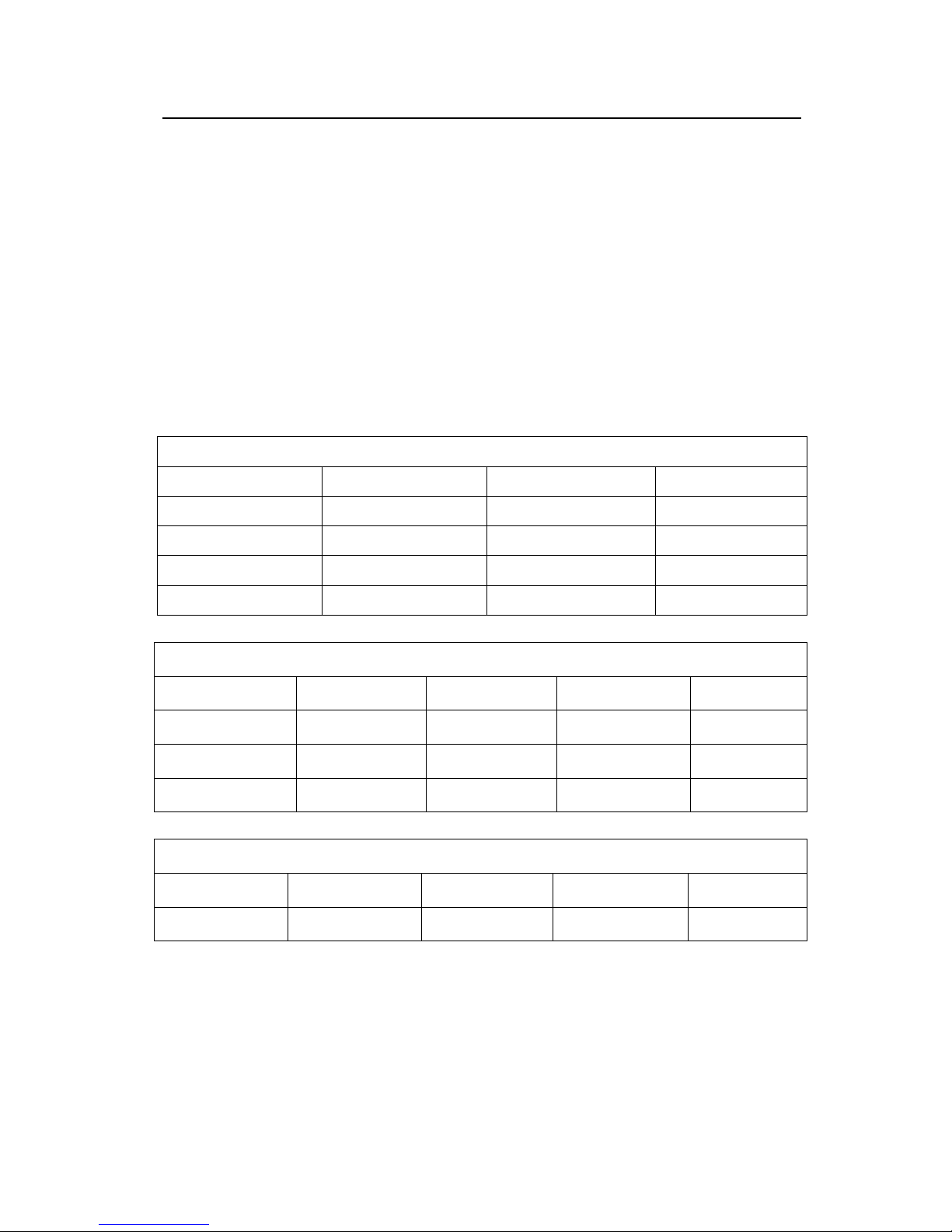
1.2 Appearance of C Series Display Cube
C Series Display Cube with Rear Access:
50〃, 60〃, 67〃, 70〃
80〃
Page 12
User Manual Visionpro
®
C Series Display Cube
- -
5
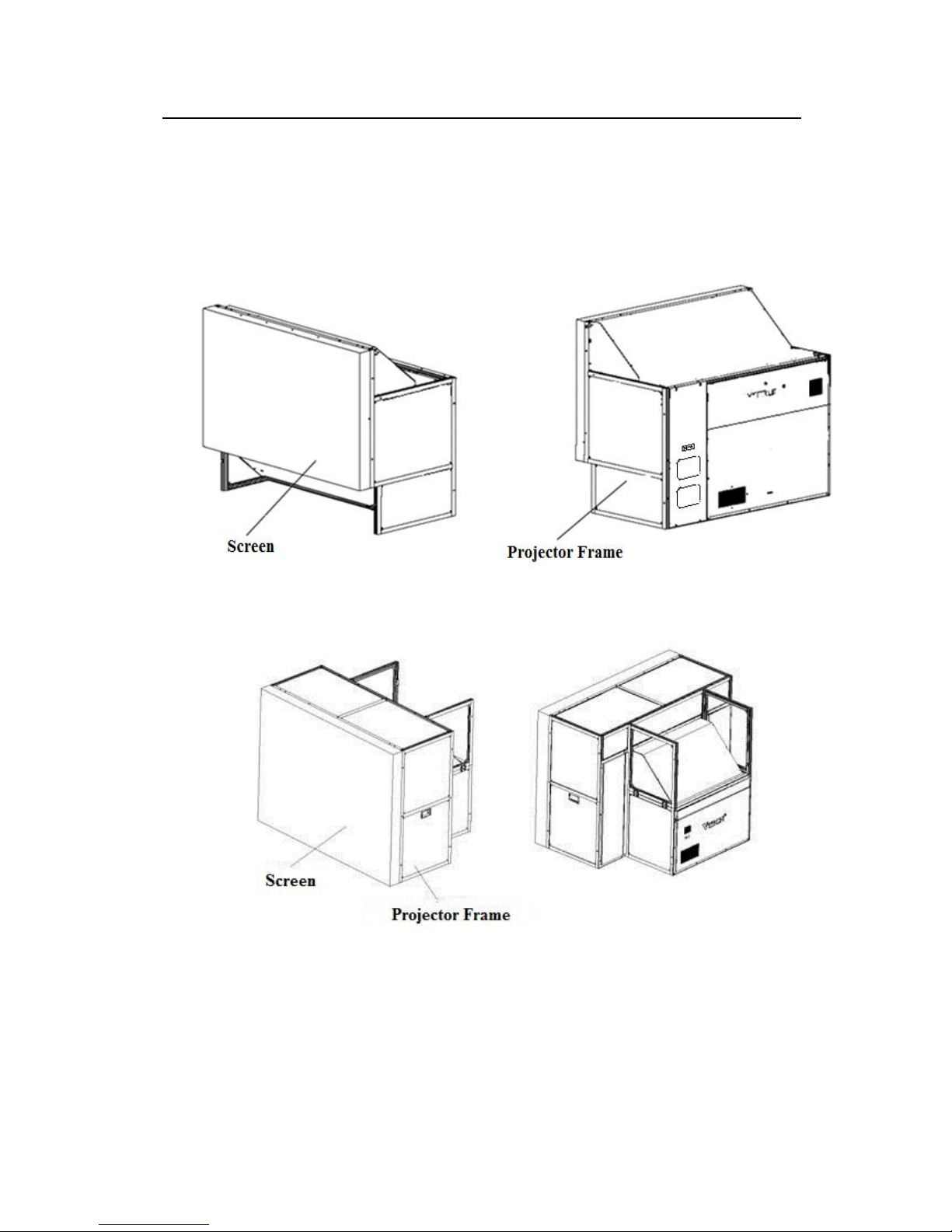
C Series Display Cube with Front Access:
The overall view
The front view
The rear view
Page 13
User Manual Visionpro
®
C Series Display Cube
- -
6
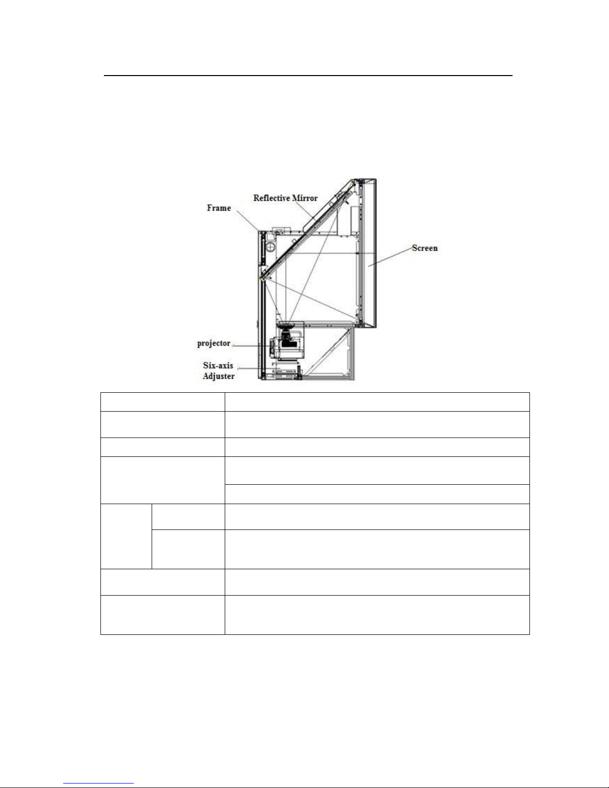
1.3 Main Components of C Series Display Cube
The Visionpro® C series display cube consists of the following parts. The relevant
functions are described in the following table.
Item
Function
Frame
A part of the structure for positioning and installing the
components of the integrated digital display cube.
Screen
Displays the image received from reflective mirror.
Reflective Mirror
1)Reflects the visual optical signal from the digital display
component to the screen;
2)Reduces the thickness of the integrated digital cube.
Projector
Engine
Converts the digital signal in TMDS format to an image signal to
produce image information
Interface Box
Converts computer signal into a digital signal in TMDS format
and inputs the signal to the projector. It also provides a control
port for receiving the control signal from the computer.
Power Module
It is embedded in the display cube frame and used to supply
power to the engine and interface box.
Six-axis Adjuster
The mechanical position adjustment part of the projector, which
is used to ensure the complete and correct output of the display
image to the screen.
Page 14
User Manual Visionpro
®
C Series Display Cube
- -
7
1.4 Technical Specifications of C Series Display Cube
The following technical specifications are only for display cubes with standard
configuration. The detailed specifications may be different from the standard one due to
the different “optional components" you purchased.
Item
Standard Configuration
XGA Display Cube
SXGA+ Display Cube
1080P Display Cube
Display Technology
DLP technology
(0.7〞DMD,
14°LVDS)
DLP technology
(0.95〞DMD, 12°LVDS)
Resolution
1024×768
1400×1050
1920×1080
Light Source
Redundant LED
Gap(*)
C series display cube with rear access : 0.3-0.5 mm
1.0mm≤C series display cube with front access≤2.5mm
3D display cube< 0.3 mm
Control Mode
Network control (RJ45): 10M/100M self-adaptive Ethernet port ,
Wireless remote control(optional)
Power
Type
1+1 redundant hot-swappable power
Frequency
50/60Hz
Consumption
145W - 350W
Operating
Environment
Temperature
0-35℃ ( optimal temperature:23℃±5 ℃ )
Humidity
30-80% (no condensation)
Certification
CCC, CE, CB, ROHS
Note:
(*)The gap may differ according to screen type and operating environment (e.g., temperature,
humidity). To ensure precision, the operating temperature and humidity is recommended to
be within 24±2ºC and 50%~60% respectively.
Page 15
User Manual Visionpro
®
C Series Display Cube
- -
8
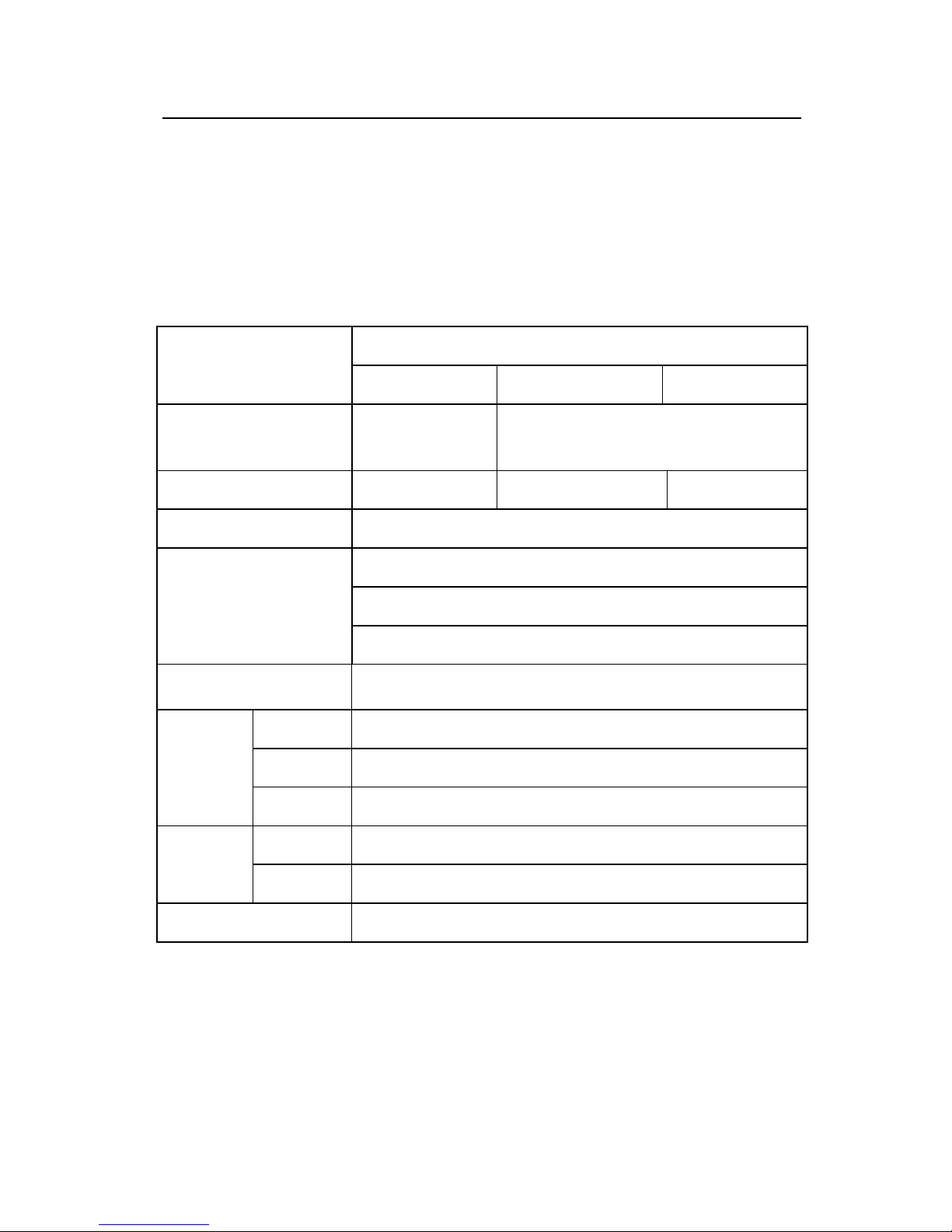
1.5 Dimensions of C Series Display Cube
XGA&SXGA+ Display Cubes:
XGA&SXGA+ Display Cubes
Frame Type
C-type with Rear Access
C-type with Front Access
Screen Diagonal(inches)
50〞
60〞
67〞
80〞
60〞
67〞
Dimension(mm)
W
1000
1220
1370
1620
1220
1370
H1
750
915
1028
1215
915
1028
D
710
765
815
995
795
820
H2
995
1250
1388
1535
1250
1388
Page 16
User Manual Visionpro
®
C Series Display Cube
- -
9
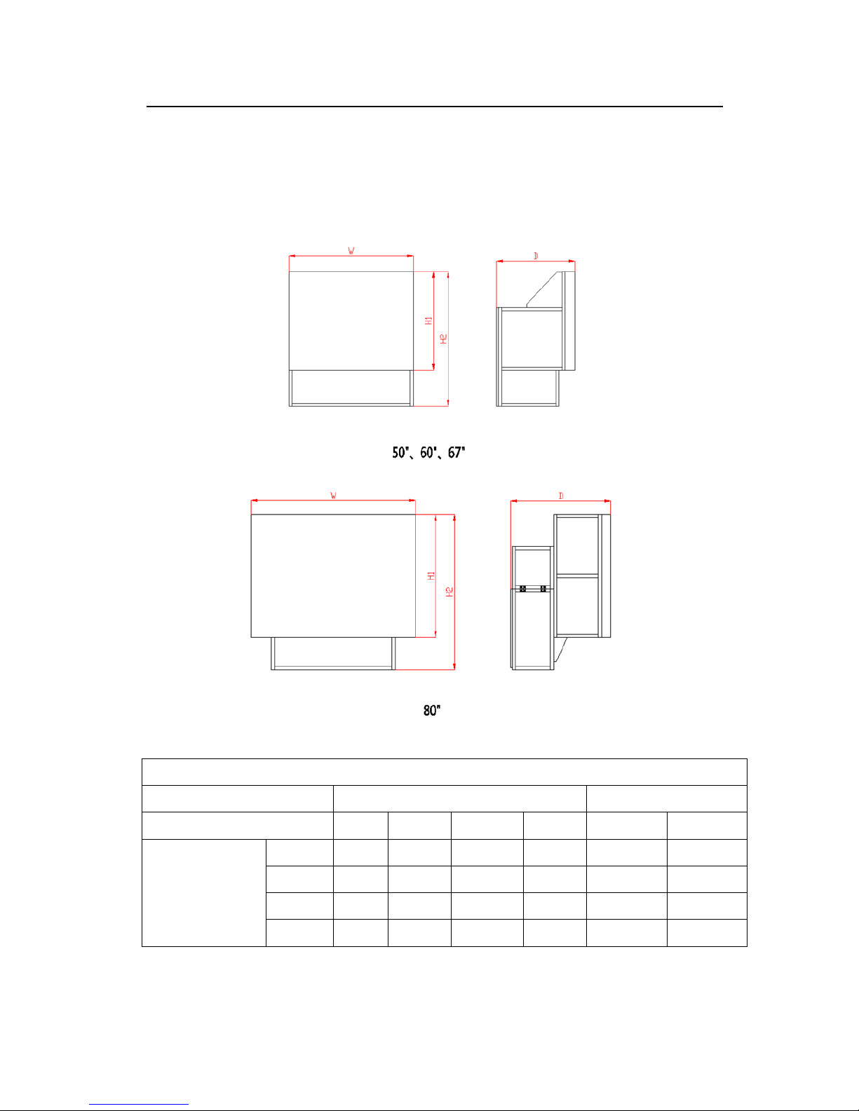
1080P Display Cube:
1080P Display Cube
Frame Type
C-type with Rear Access
C-type with Front Access
Screen Diagonal(inches)
60〞
70〞
70〞
Dimension(mm)
W
1330
1552
1552
H1
748
872
872
D
750
795
803
H2
988
1172
1172
Page 17

User Manual Visionpro
®
C Series Display Cube
- -
10
2 Projector of C Series Display Cube
The projector is very important as its performance will directly affect the visual
quality of the cube and the wall. The projector of C series display cube, a digital
display device composed of engine and interface box, is one of the most significant
components of VTRON Video Wall.
The product meets the national standards and technical codes and has obtained
certificates of CCC, CE, CB, ROHS, etc.
2.1 Engine Overview
Appearance 1:
Page 18

User Manual Visionpro
®
C Series Display Cube
- -
11
Appearance 2:
SN
Name
①
Filter
②
DVI port
③
Lens
④
IR receiver/Standby status LED indicator
⑤
Fan
⑥
Grounding screw
⑦
Expansion port
⑧
Power input port
Page 19

User Manual Visionpro
®
C Series Display Cube
- -
12
2.2 Interface Box Overview
VCl-3 interface box, VCL-3+ interface box, and VCL-3A interface box are
available for C series display cube. The detailed interface configuration depends on
the type of the cube.
2.2.1 Appearance of the Interface Box
VCL-3 Interface Box:
Page 20

User Manual Visionpro
®
C Series Display Cube
- -
13
VCL-3+ Interface Box:
Page 21

User Manual Visionpro
®
C Series Display Cube
- -
14
VCL-3A Interface Box:
VCL-3/VCL-3+/VCL-3A Interface Box:
SN
Name
①
Pull-out power module of VCL-3 interface box
Dual AC power module of VCL-3+ interface box
Dual power module of VCL-3A interface box
②
Main control board (optional)
③
Signal processing board (optional)
④
DVI output port
⑤
Power output port ( low voltage)
⑥
Grounding screw
Page 22

User Manual Visionpro
®
C Series Display Cube
- -
15
⑦
Power output port of the VCL-3 interface box
Expansion port of the VCL-3A interface box
⑧
Power input port (low voltage) of VCL-3+ interface box
Power output port(low voltage) of VCL-3A interface box
2.2.2 Boards of VCL-3/VCL-3+ /VCL-3A Interface Box
CP30SC Main Control Board(For VCL-3,VCL-3+ and VCL-3A interface
boxes)
CP30SC Main Control Board
7-SEG LED indicator
Desktop signal input port
Ethernet port
RS232 serial debug port
Sync signal input port
Sync signal output port
ON/OFF button
Page 23

User Manual Visionpro
®
C Series Display Cube
- -
16
Specifications of CP30SC Main Control Board
DVI Output Port
Connector Type
DVI-D
Signal Format
TMDS
Dot Clock Frequency
25MHz-165MHz
Horizontal Frequency
35KHz-75KHz
Vertical Frequency
50Hz/60Hz
Resolution
640 × 480-1920×1200
Color Depth
24bit
Control Mode
I2C, SCL Frequency<100KHz
Input/ Output Ports of CP30SC Main Control Board
1)Desktop Signal Input Port
Digital
Connector Type
DVI-I
Signal Format
TMDS
Dot Clock Frequency
25-165MHz
Horizontal Frequency
31KHz-75KHz
Vertical Frequency
59Hz-61Hz
Resolution
640x480-1920x1200
Color Depth
24bit
Analog
Connector Type
DVI-I
Signal Format
RGBHV, RGsB
Dot Clock Frequency
25-165MHz
Horizontal Frequency
31KHz-75KHz
Vertical Frequency
59Hz-61Hz
Resolution
640×480~1920×1200
Color Depth
24bit
Sync Signal Amplitude
0.7Vpp~5.5Vpp
Sync Signal (green) Amplitude
-0.5Vpp~-0.3Vpp
RGB Signal Amplitude
0.5Vpp~1.0Vpp
2)Sync Signal Input/Output Port
Connector Type
BNC×2
Sync Signal Frequency
50~60HZ
Sync Signal Amplitude
3.0V~~3.6Vpp
Page 24

User Manual Visionpro
®
C Series Display Cube
- -
17
3)Ethernet Port
Connector Type
RJ45
Port Type
Standard 100M/10M Self-adaptive Ethernet Port
CP30DSC Main Control Board(For VCL-3+ interface box only)
CP30DSC Main Control Board (3D Display Cube)
Specifications of CP30DSC Main Control Board (3D Display Cube)
DVI Output Port
Connector Type
DVI-I
Signal Format
TMDS
Dot Clock Frequency
65MHz-330MHz
Horizontal Frequency
35KHz-135KHz
Vertical Frequency
60Hz/120Hz
Resolution
1024×768/1400×1050/1920×1080
Color Depth
24bit
Control Mode
I2C,SCL Frequency<100KHz
7-SEG LED indicator
Power output port(low voltage)
Master desktop signal input port
Slave desktop signal input port
Signal loop-out port
Signal loop-in port
Ethernet port
Sync signal input port
Sync signal output port
ON/OFF button
Page 25

User Manual Visionpro
®
C Series Display Cube
- -
18
Input/Output Ports of CP30DSC Main Control Board
1)Master Desktop Signal Input Port
Connector Type
DVI-D
Signal Format
TMDS
Dot Clock Frequency
25-330MHz
Horizontal Frequency
31KHz-135KHz
Vertical Frequency
24Hz/30Hz/60Hz/120Hz
Resolution
640x480-4096x2160
Color Depth
24bit
2)Slave Desktop Signal Input Port
Connector Type
DVI-D
Signal Format
TMDS
Dot Clock Frequency
25-330MHz
Horizontal Frequency
31KHz-135KHz
Vertical Frequency
24Hz/30Hz/60Hz/120Hz
Resolution
640x480-4096x2160
Color Depth
24bit
3)Signal Loop-in Port
Connector Type
DisplayPort
Signal Format
SERDES
Dot Clock Frequency
27-330MHz
Horizontal Frequency
31KHz-135KHz
Vertical Frequency
23Hz-121Hz
Resolution
640x480-4096x2160
Color Depth
24bit
4)Signal Loop-out Port
Connector Type
DisplayPort
Signal Format
SERDES
Dot Clock Frequency
27-330MHz
Horizontal Frequency
31KHz-135KHz
Vertical Frequency
23Hz-121Hz
Resolution
640x480-4096x2160
Color Depth
24bit
Page 26

User Manual Visionpro
®
C Series Display Cube
- -
19
5)Sync Signal Input/Output Port
Connector Type
BNC×2
Sync Signal Frequency
60/120Hz
Sync Signal Amplitude
3.0V~~3.6Vpp
6)Ethernet Port
Connector Type
RJ45
Port Type
Standard 100M/10M Self-adaptive Ethernet Port
Page 27

User Manual Visionpro
®
C Series Display Cube
- -
20
CP30SCIP Main Control Board (For VCL-3A interface box only)
CP30SCIP Main Control Board
RS232 serial debug port
Sync signal output port
Sync signal input port
ON/OFF button
Ethernet port/ IP signal input port 1
Ethernet port/ IP signal input port 2
Desktop signal input
Desktop signal input port
7-SEG LED indicator
Page 28

User Manual Visionpro
®
C Series Display Cube
- -
21
Specifications of CP30SCIP Main Control Board
DVI Output Port
Connector Type
DVI-D
Signal Format
TMDS
Dot Clock Frequency
25MHz-165MHz
Horizontal Frequency
35KHz-75KHz
Vertical Frequency
50Hz/60Hz
Resolution
640 × 480-1920×1200
Color Depth
24bit
Control Mode
I2C, SCL Frequency<100KHz
Input/ Output Ports of CP30SCIP Main Control Board
1)Desktop Signal Input Port
Digital
Connector Type
DVI-D
Signal Format
TMDS
Dot Clock Frequency
27-165MHz
Horizontal Frequency
31KHz-100KHz
Vertical Frequency
23Hz-121Hz
Resolution
640×480-1920×1200
Color Depth
24bit
2)Ethernet Port
Connector Type
RJ45×2
Port Type
Standard 100M/10M Self-adaptive Ethernet port
3)Sync Signal Input/Output Port
Connector Type
BNC×2
Sync Signal Frequency
50~60HZ
Sync Signal Amplitude
3.0V~~3.6Vpp
Page 29

User Manual Visionpro
®
C Series Display Cube
- -
22
Note:
(1)7-SEG LED Indicator
The 7-SEG LED indicator is controlled through 3 I/O ports. Different display content
indicates different system status. Details are shown in the following table.
Content
System Status
Content
System Status
0
Interface box powered up,
loading program started
0.
Error loading program
1
Application initialization
1.
Error during application initialization
2
IP configuration (static IP or
dynamic IP)
2.
IP configuration failure
3
Interface box started, main
control board powered up
3.
Error starting interface
4
Downloading FPGA program
of main control board
4.
Error downloading FPGA program of
main control board
5
Configuration of FPGA
parameters of main control
board
5.
Error configuring FPGA parameters of
main control board
6
Engine powered on
6.
Error starting engine
7
Waiting for the completion of
engine initialization
7.
Engine initialization error
8
Configuring engine
8.
Engine configuration failure
9
Engine detection
9.
Display failure
E
E.
There are two situations in which E is
displayed: 1. An error is detected, but
this error is not serious enough to
trigger the protection mode. For the
moment, this only includes the DVI
disconnection error. 2. It is displayed
during the 1-minute waiting time before
entering the protection mode.
.
Flashing: engine is shutting
down
.
Standby
Normal operation
Page 30

User Manual Visionpro
®
C Series Display Cube
- -
23
Note:
A. The 7-SEG LED indicator displays a random value in the first several seconds of power-up
because it takes several seconds from power-up to the initialization of the 7-SEG LED
indicator.
B. If the alarm forces the engine to enter the protection mode, an alarm message will be sent to
remind the user of the failure, and then the engine will enter the protection mode and shut down
in 1 minute.
(2)RS232 Serial Debug Port
RS232 serial debug port is used to debug during development or in the event of an RJ-45
failure. It is connected to the engine through D-Sub 9 Pins Male Connector. Details are shown
as below.
Pin No.
Input/Output
Signal
1 — N.C
2
Input
RD(Receive Data)
3
Output
SD(Send Data)
4 — N.C
5
—
SG(Signal Ground)
6 — N.C 7 —
N.C 8 —
N.C 9 —
N.C
(3)ON/OFF Button
When the projector is powered up and in standby mode, press and hold this button for 2 to
3 seconds to start the projector. When the projector is in its normal operating mode, press and
holds this button for 2 to 3 seconds to shut down the projector. The fan will stop in 1 to 2
seconds after the projector shuts down.
Page 31

User Manual Visionpro
®
C Series Display Cube
- -
24
E-CP30VR02 Signal Processing Board(Optional)
E- CP30VR02 Signal Processing Board
Specifications of E-CP30VR02 Signal Processing Board
VIDEO Signal Input Port
CVBS
Connector Type
BNCx1
Signal Format
CVBS
Signal System
PAL, NTSC, SECAM
Signal Amplitude
0.5 Vpp~2.0Vpp
VIDEO signal input port
S_VIDEO signal input port
HDMI signal input port
Signal loop-out port
DRGB signal input port
ARGB signal input port
Signal loop-in port
Page 32

User Manual Visionpro
®
C Series Display Cube
- -
25
S_VIDEO Signal Input Port
YPrPb
Connector Type
S_VIDEO
Signal Format
YPrPb
Resolution
480i, 480p, 576i, 576P, 720P, 1080i,1080p
Signal Amplitude
0.5Vpp~1.0Vpp
YC
Connector Type
S_VIDEO
Signal Format
YC
Signal System
PAL, NTSC, SECAM
Signal Amplitude
0.5 Vpp~2.0Vpp
HDMI Signal Input Port
Digital
Connector Type
HDMI
Signal Format
TMDS
Dot Clock Frequency
25-165MHz
Horizontal Frequency
31KHz-100KHz
Vertical Frequency
24~60Hz
Resolution
480i, 480p, 576i, 576P, 720P, 1080i,1080p
Color Depth
24bit
RGB Signal Input Port
Digital
Connector Type
DVI-D
Signal Format
TMDS
Dot Clock Frequency
27-165MHz
Horizontal Frequency
31KHz-100KHz
Vertical Frequency
23Hz-121Hz
Resolution
640×480~1920×1200
Color Depth
24bit
Analog
Connector Type
BNCx5
Signal Format
RGBHV, RGsB
Dot Clock Frequency
27-165MHz
Horizontal Frequency
31KHz-100KHz
Vertical Frequency
23Hz-121Hz
Resolution
640x480~1600×1200( including 1920×1080)
Page 33

User Manual Visionpro
®
C Series Display Cube
- -
26
Color Depth
24bit
Sync Signal Amplitude
2.5Vpp~5.5Vpp
Sync Signal (green) Amplitude
-0.5Vpp~-0.3Vpp
RGB Signal Amplitude
0.5Vpp~1.0Vpp
Signal Loop-in/Loop-out Port
Loop-in
Connector Type
DVI-D
Signal Format
TMDS
Dot Clock Frequency
27-165MHz
Horizontal Frequency
31KHz-100KHz
Vertical Frequency
23Hz-121Hz
Resolution
640x480~1920×1200
Color Depth
24bit
Loop-out
Connector Type
DVI-D
Signal Format
TMDS
Dot Clock Frequency
27~165MHz
Horizontal Frequency
31KHz-100KHz
Vertical Frequency
23Hz~121Hz
Resolution
640x480~1920×1200
Color Depth
24bit
Page 34

User Manual Visionpro
®
C Series Display Cube
- -
27
E-CP30VR04II Signal Processing Board
E-CP30VR04II Signal Processing Board
Specifications of E-CP30VR04II Signal Processing Board
VIDEO Signal Input Port
CVBS
Connector Type
BNCx1
Signal Format
CVBS
Signal System
PAL, NTSC, SECAM
Signal Amplitude
0.5 Vpp~2.0Vpp
VIDEO signal input port
S_VIDEO signal input port
HDMI signal input port
ARGB signal input port
DRGB signal input port
Signal loop1-out port
Signal loop1-in port
Signal loop2-out port
Signal loop2-in port
Page 35

User Manual Visionpro
®
C Series Display Cube
- -
28
S_VIDEO Signal Input Port
YPrPb
Connector Type
S_VIDEO
Signal Format
YPrPb
Resolution
480i, 480p, 576i, 576P, 720P, 1080i,1080p
Signal Amplitude
0.5Vpp~1.0Vpp
YC
Connector Type
S_VIDEO
Signal Format
YC
Signal System
PAL, NTSC, SECAM
Signal Amplitude
0.5 Vpp~2.0Vpp
HDMI Signal Input Port
Digital
Connector Type
HDMI
Signal Format
TMDS
Dot Clock Frequency
25-165MHz
Horizontal Frequency
31KHz-100KHz
Vertical Frequency
24~60Hz
Resolution
480i, 480p, 576i, 576P, 720P, 1080i,1080p
Color Depth
24bit
RGB Signal Input Port
Digital
Connector Type
DVI-D
Signal Format
TMDS
Dot Clock Frequency
27-165MHz
Horizontal Frequency
31KHz-100KHz
Vertical Frequency
23Hz-121Hz
Resolution
640×480~1920×1200
Color Depth
24bit
Analog
Connector Type
BNCx5
Signal Format
RGBHV、RGsB
Dot Clock Frequency
27-165MHz
Horizontal Frequency
31KHz-100KHz
Vertical Frequency
23Hz-121Hz
Resolution
640x480~1600×1200( including 1920×1080)
Color Depth
24bit
Sync Signal Amplitude
2.5Vpp~5.5Vpp
Sync Signal (green) Amplitude
-0.5Vpp~-0.3Vpp
RGB Signal Amplitude
0.5Vpp~1.0Vpp
Page 36

User Manual Visionpro
®
C Series Display Cube
- -
29
Signal Loop-in/Loop-out Port
Signal Loop1-in Port
Connector Type
DisplayPort
Signal Format
SERDES
Dot Clock Frequency
27 MHz ~330MHz
Horizontal Frequency
31KHz~135KHz
Vertical Frequency
23Hz~121Hz
Resolution
640×480~4096×2160
Color Depth
24bit
Signal Loop1-out Port
Connector Type
DisplayPort
Signal Format
SERDES
Dot Clock Frequency
27 MHz ~330MHz
Horizontal Frequency
31KHz~135KHz
Vertical Frequency
23Hz~121Hz
Resolution
640×480~4096×2160
Color Depth
24bit
Signal Loop2-in Port
Connector Type
DisplayPort
Signal Format
TMDS
Dot Clock Frequency
27 MHz ~165MHz
Horizontal Frequency
31KHz~135KHz
Vertical Frequency
23Hz~121Hz
Resolution
640×480~1920×1200
Color Depth
24bit
Signal Loop2-out Port
Connector Type
DisplayPort
Signal Format
TMDS
Dot Clock Frequency
27 MHz ~165MHz
Horizontal Frequency
31KHz~135KHz
Vertical Frequency
23Hz~121Hz
Resolution
640×480~1920×1200
Color Depth
24bit
Page 37

User Manual Visionpro
®
C Series Display Cube
- -
30
E-CP30SKD04 Signal Processing Board (Optional)
E-CP30SKD04 Signal Processing Board
SDI1 signal input port
SDI2 signal input port
DRGB1 signal input port
Signal loop1-out port
Signal loop1-in port
DP signal input port
HDMI signal input port
DRGB2 signal input port
Signal loop2-out port
Signal loop2-in port
Page 38

User Manual Visionpro
®
C Series Display Cube
- -
31
Specifications of E-CP30SKD04 Signal Processing Board
SDI Signal Input Port
SDI
Connector Type
BNCx2
Signal Format
SDI
Resolution
480i, 576i., 720p, 1080i, 1080p
Vertical Frequency
23.98Hz~60Hz
Signal Amplitude
0.8Vpp
HDMI Signal Input Port
Digital
Connector Type
HDMI
Signal Format
TMDS
Dot Clock Frequency
25~300MHz
Horizontal Frequency
31KHz-100KHz
Vertical Frequency
24~60Hz
Resolution
640×480~4096×2160
Color Depth
24bit
DP Signal Input Port
Digital
Connector Type
DisplayPort
Signal Format
micro-packet
Dot Clock Frequency
25~300MHz
Horizontal Frequency
31KHz-100KHz
Vertical Frequency
24Hz~60Hz
Resolution
640×480~4096×2160
Color Depth
24bit
RGB Signal Input Port
Digital
Connector Type
DVI-D × 2
Signal Format
TMDS
Dot Clock Frequency
27~330MHz
Horizontal Frequency
31KHz~100KHz
Vertical Frequency
23Hz-121Hz
Resolution
640×480~4096×2160
Color Depth
24bit
Page 39

User Manual Visionpro
®
C Series Display Cube
- -
32
Signal Loop-in/Loop-out Port
Signal Loop1-in Port
Connector Type
DisplayPort
Signal Format
SERDES
Dot Clock Frequency
27~330MHz
Horizontal Frequency
31KHz~100KHz
Vertical Frequency
23Hz-121Hz
Resolution
640×480~4096×2160
Color Depth
24bit
Signal Loop1-out Port
Connector Type
DisplayPort
Signal Format
SERDES
Dot Clock Frequency
27~330MHz
Horizontal Frequency
31KHz~100KHz
Vertical Frequency
23Hz~121Hz
Resolution
640×480~4096×2160
Color Depth
24bit
Signal Loop2-in Port
Connector Type
DisplayPort
Signal Format
TMDS
Dot Clock Frequency
27-165MHz
Horizontal Frequency
31KHz~135KHz
Vertical Frequency
23Hz-121Hz
Resolution
640×480~1920×1200
Color Depth
24bit
Signal Loop2-out Port
Connector Type
DisplayPort
Signal Format
TMDS
Dot Clock Frequency
27~165MHz
Horizontal Frequency
31KHz~135KHz
Vertical Frequency
23Hz~121Hz
Resolution
640×480~1920×1200
Color Depth
24bit
Note:
(1)SDI1 signal input port and SDI2 signal input port are backups for each other.
(2)DRGB1 signal input port and DRGB2 signal port are backups for each other.
Page 40

User Manual Visionpro
®
C Series Display Cube
- -
33
E-CP30SDI02 Signal Processing Board ( Optional)
CP30SDI02 Signal Processing Board
Specifications of E-CP30SDI02 Signal Processing Board
SDI Signal Input Port
SDI
Connector Type
BNCx2
Signal Format
SDI
Resolution
480i, 576i, 720p, 1080i, 1080p
Vertical Frequency
23.98Hz~60Hz
Signal Amplitude
0.8Vpp
HDMI signal input port
Signal loop2 port
Signal loop1 port
SDI1 signal input port
Genlock sync signal input port
Vertical sync signal output port
SDI2 signal input port
Page 41

User Manual Visionpro
®
C Series Display Cube
- -
34
Genlock Sync Signal Input Port/ Vertical Sync Signal Output Port
Genlock
Connector Type
BNC×2
Sync Signal Frequency
50~60Hz
Sync Signal Input Amplitude
3.0V~~5.5Vpp
Sync Signal Input Amplitude(Analog
black burst/HD tri-level sync)
0.3Vpp~1.2Vpp
Sync Signal Output Amplitude
3.0V~~3.6Vpp
HDMI Signal Input Port
Digital
Connector Type
HDMI
Signal Format
TMDS
Dot Clock Frequency
27MHz-165MHz
Horizontal Frequency
31KHz-100KHz
Vertical Frequency
50~60Hz
Resolution
480i, 480p, 576i, 576P, 720P, 1080i,1080p
Color Depth
24bit
Signal Loop Port
Signal Loop1-in Port
Connector Type
Dual-DVI
Signal Format
TMDS
Dot Clock Frequency
27-165MHz
Horizontal Frequency
31KHz-100KHz
Vertical Frequency
23Hz-121Hz
Resolution
640×480~1920×1200
Color Depth
24bit
Signal Loop1-out Port
Connector Type
Dual-DVI
Signal Format
TMDS
Dot Clock Frequency
27~165MHz
Horizontal Frequency
31KHz~100KHz
Vertical Frequency
23Hz~121Hz
Resolution
640×480~1920×1200
Color Depth
24bit
Page 42

User Manual Visionpro
®
C Series Display Cube
- -
35
Signal Loop2-in Port
Connector Type
Dual-DVI
Signal Format
TMDS
Dot Clock Frequency
27-165MHz
Horizontal Frequency
31KHz-100KHz
Vertical Frequency
23Hz-121Hz
Resolution
640×480~1920×1200
Color Depth
24bit
Signal Loop2-out Port
Connector Type
Dual-DVI
Signal Format
TMDS
Dot Clock Frequency
27~165MHz
Horizontal Frequency
31KHz~100KHz
Vertical Frequency
23Hz~121Hz
Resolution
640×480~1920×1200
Color Depth
24bit
Note:
(1) Two channels of SDI signal back up each other.
(2) Vertical sync signal output port of E-CP30SDI02 signal processing board put out the
signal generated from Genlock sync signal to the sync signal input port of main control
board. Once one of the display cubes acquired the signal, its sync signal output port will
have loop-through to sync signal input port of the other cube till all cubes of the wall are
looped. Schematic diagram for synchronization looping is shown in the following
figure:
Page 43

User Manual Visionpro
®
C Series Display Cube
- -
36
Page 44

User Manual Visionpro
®
C Series Display Cube
- -
37
3Network Environment for the Video Wall System
The interactions of cubes, processors, network switches, and VWAS server are
based on network communication and they are configured by certified professionals. If
you need assistance, please consult VTRON professional services.
Warning: NO connection to the external network!
Details are shown in the following figure:
Page 45

User Manual Visionpro
®
C Series Display Cube
- -
38
4 Installation of C Series Display Cube
4.1 VTRON DLPTM Digital Video Wall System
Linear Video Wall
A linear video wall can be lined up and stacked by M×N display cubes and N
pedestals. A 2×2 linear video wall is shown as below.
Page 46

User Manual Visionpro
®
C Series Display Cube
- -
39
Curved Video Wall
A curved video wall can be lined up and stacked by M×N display cubes and N
pedestals. A 3×5 curved video wall is shown as below.
Note: 3D display cubes do not allow setting up a curved video wall temporarily.
Page 47

User Manual Visionpro
®
C Series Display Cube
- -
40
4.2 System Configuration
A basic video wall system is composed of display cubes, one or more multi-screen
processors, pedestals and other devices. Configuration for a 3×5 video wall system is
shown in the following figure.
Page 48

User Manual Visionpro
®
C Series Display Cube
- -
41
4.3 Grounding of the Video Wall System
The engine and interface box of every display cube must be connected to the
grounding wire. Detailed grounding for a 2×2 video wall system is shown as below.
Warning
The system must be installed by VTRON or its agent. You must not move or change the
grounding, otherwise personal or equipment safety may be endangered.
Page 49

User Manual Visionpro
®
C Series Display Cube
- -
42
5 System ON/OFF
Before starting the system:
1. Please make sure all cables are reliably connected and securely fastened;
2. Please make sure the system is properly grounded;
3. Please make sure the power switch of the display cube is in ON status;
4. Please make sure the lens cover is removed.
Startup Steps:
1. Turn on the power switch of the signal system and input signal;
2. Turn on the power supply of the multi-screen processor;
3. Turn on the power supply of the PC running VWAS;
4. When the multi-screen processor completes its self-detection, start the control
system software on the PC and start the display cubes with the control system
software.
Note:
1. Turn on the display cube after it has been powered up for one minute;
2. It will take some time for the display cube to display any content after startup. Do
not repeatedly press the POWER button in the control software.
Shutdown Steps:
1. Shut down the multi-screen processor and turn off its power switch when the
prompt for safe shutdown appears.
2. Shut down the display cubes with control software on PC and then shut down the
PC.
3. Turn off the power switch of interface box when the fan of projector stops.
Note: Any forced power-off may cause damage to the system.
Warning
The system commissioning and parameter adjustment can only be performed by trained
and qualified professionals.
Page 50

User Manual Visionpro
®
C Series Display Cube
- -
43
6 Precautions
Please read the following carefully and strictly comply with the following safety
precautions before and during daily maintenance and troubleshooting. This is very
important for protecting your safety and your equipment.
1. Before disconnecting or connecting any electrical devices, please make sure the
system has been shut down and the system power cable has been unplugged.
2. Please make sure all system devices are properly grounded.
3. Do not open the top cover of the display cube.
4. Do not spray any chemical or other liquid on or near the digital video wall system.
5. Do not place any wet or heating objects near the system devices.
6. Do not make any changes or add any components to the original electrical and
mechanical design of the display cube.
7. Do not place anything in or above the ventilation hole and ventilation slot.
8. Please strictly comply with the required startup/shutdown steps of the Visionpro
®
series display cube.
9. Please put the display cube in a place with good ventilation.
10. The air outlet of the central air conditioner must be at least 1 m away from the front
projection of the video wall system and the air outlet of a cabinet air conditioner
must not blow directly to the video wall system.
Warning
The VTRON digital display cube is a specialized display and control system. If you need
to install additional software, be sure to consult VTRON or its agent first.
Page 51

User Manual Visionpro
®
C Series Display Cube
- -
44
7 Daily Maintenance
1. Please use dedicated cleaning tools to clean the screen surface of the display cube;
2. Do not touch the screen surface with your hands;
3. Please use dedicated cleaning tools to clean lens;
4. Do not replace the LED light source for yourself;
5. Please keep a clean, dust-free, and well- ventilated environment for the display
system.
6. Please regularly check the connection of all cables.
7. Please turn on and run the system for 1 to 2 hours each week, if the system is not
frequently used. In damp seasons, once or more per day is recommended.
Light Source
Note:
During projector operation, avoid looking directly at the lens.
It is normal for the brightness of the light source to be reduced when it is close to the end
of its lifetime.
Fan
Do not place any objects in or on the ventilation hole in the projector to ensure proper
ventilation and heat dissipation.
Grounding
Please ensure that the grounding wires of both the display system and the power
supply are at the same level and that they are connected to the ground in order to prevent
lightning and static damage.
Operating Environment
Please keep a clean, dust-free and well-ventilated environment for the display system.
Cable Connections
Please use cables provided by VTRON and regularly check the connection of all
cables.
Page 52

User Manual Visionpro
®
C Series Display Cube
- -
45
Warning
The replacement of the light source under special circumstances must be performed by
professionals from VTRON.
8 Trouble Shooting
Normal Startup Process for the Projector
1) Connect the power supply and turn on the power switch, and then the projector
will automatically update the corresponding information in the FLASH memory.
2) The projector can be started when the standby status LED is on. Afterward, the
fan will start and the LED light source will turn on.
Troubleshooting
1. No response when power is turned on:
a) Check to see if the power supply is operating normally with a multimeter.
b) Check to see if the connecting cable between the interface and engine is firmly
connected.
c) Check to see if the power switch is turned on.
2. No image is displayed after device is turned on:
(1) No warning signal is displayed
a) Check to see if the signal cables are connected correctly.
b) Check to see if the signal output of the signal source is normal.
(2) Warning signal is displayed
Please consult professional service personnel.
Page 53

User Manual Visionpro® C Series Display Cube
- -
46
9 Contact Us
About after sales service matters please contact after sales department of VTRON
GROUP CO.,LTD.
VTRON GROUP CO.,LTD.
No. 233 Kezhu Road, Guangzhou Hi-Tech Industrial Development Zone
(Guangzhou Science City),
Guangzhou 510670, China
Tel: +86-20-8390-8888
Fax: +86-20-8390-3591
Email: INFO@VTRON.COM
VTRON GROUP CO.,LTD. (Hong Kong)
Unit 1608-09, 16/F, Tower 1, 193 Prince Edward Road West, Grand Century
Place Mongkok, Kowloon Hong Kong
Tel: +852-2264-3688
Fax: +852-2264-3833
Email: INFO@VTRON.COM
VTRON Hong Kong Technical Support Centre
Unit 1225, 12/F, Corporation Park,11 On Lai Street,
Shatin, New Territories, Hong Kong
Tel: +852-2613-9708
Fax: +852-2613-9277
Email: INFO@VTRON.COM
VTRON GROUP CO.,LTD. (Malaysia Rep Office)
Unit 29-6 Block E1, Dataran Prima Business Centre, Jalan PJU 1/42, Petaling
Jaya 47301, Selangor Darul Ehsan, Malaysia.
Tel: +603-7880-0338
Fax: +603-7887-0304
 Loading...