

User Manual Rev.1.2.2 EN
Network Drive Recorder
FPRO300

Index

2
1. Before reading this user manual .................................... 4
1.1 Important safety information ........................................ 5
2. Getting to know the network drive recorder ................. 7
2.1 Unpacking .................................................................... 8
2.2 Optional Accessories ................................................... 9
2.3 Part & Names ............................................................. 10
2.4 Terminal Ports ............................................................ 14
2.4.1 GPS IN ................................................................. 14
2.4.2 VIDEO OUT ......................................................... 14
2.4.3 CAMERA IN ......................................................... 15
2.4.4 MicroUSB ............................................................. 16
2.4.5 USB ...................................................................... 16
2.4.6 Reset button ......................................................... 17
2.4.7 Microphone(MIC) ................................................. 17
3. Getting ready to start recording ................................... 19
3.1 Selecting a suitable memory card .............................. 20
3.2 Handing a memory cards ........................................... 21
3.3 format memory cards ................................................. 22
3.4 How to update firmware ............................................. 25
3.5 To insert a memory card ............................................. 27
3.5.1 To eject a memory card ........................................ 27
3.6 Connect external memory .......................................... 28
4. Installation ...................................................................... 29
4.1 Direction of Cradle ........................................... ......... 30
4.1.1 Joint the cradle with main device ............... ......... 31
4.1.2 Mounting the NDR ............................................... 31
4.1.3 PIN Assignment 1 ................................................ 34
4.1.4 PIN Assignment 1 ................................................ 35
4.2 How to fit the power loom .......................................... 36
4.3 Joint tamperproof cover ............................................. 37
5. LED Signals .................................................................... 39
5.1 LED Signals ............................................................... 40
5.1.1 System boot ......................................................... 40
5.1.2 Update setup file .................................................. 40
5.1.3 GPS signal detection ............................................ 40
5.1.4 LED signal table ................................................... 41
5.1.5 USB backup ......................................................... 41
5.1.6 Firmware update .................................................. 42
5.1.7 Remote download firmware(OTA) ........................ 42
6. Features .......................................................................... 43
6.1 Features-NDR ............................................................ 44
6.1.1 Encryption Video .................................................. 44
6.1.2 3rd Camera Recording(Extra) .............................. 44
6.1.3 Back-up gear signal cable .................................... 45
6.1.4 IR Recording ........................................................ 45
6.1.5 Cycle Recording ................................................... 45
6.1.6 Video out(Monitoring) ........................................... 46
6.1.7 Input External Trigger .......................................... 46
6.1.8 LBP(Low Battery Protection) ............................... 46
6.1.9 Voice Guide & Alarm ............................................ 46
Index

3
6.1.10 Sound Recording ............................................... 46
6.1.11 Video Overlay ..................................................... 47
6.1.12 Data Logs ........................................................... 49
6.1.13 Manual Event Recording .................................... 50
6.1.14 SOS Panic Button Recording(Extra) .................. 50
6.1.15 Excessive Speed Trigger ................................... 50
6.1.16 Motion Detection - Sleep mode .......................... 50
6.1.17 GPS(GNSS)
6.1.18 External GPS Antenna(Extra) ............................ 51
6.1.19 Map Tracking ...................................................... 51
6.1.20 G-Sensor ............................................................ 51
6.1.21 Driving Report .................................................... 52
6.1.22 Output Power DC5V ........................................... 52
6.1.23 External Memory Storage(Extra) ........................ 52
6.1.24 Wi-Fi LAN USB Adaptor(Extra) .......................... 52
6.1.25 3G/LTE USB Modem(Extra) ............................... 52
6.1.26 3G/LTE Telecommunications ............................. 53
6.1.27 Internet Telecommunications ............................. 54
7. File & Memory Structure ................................................ 55
7.1 Usage of Memory ....................................................... 56
7.1.1 Directory of NORMAL file area ............................. 56
7.1.2 Directory of EVENT file area ................................ 56
7.1.3 Directory of LOG file area .................................... 57
7.2 Recordable Time and Capacity .................................. 58
7.2.1 Recorded File size ............................................... 58
7.2.2 Recorded Time - 2Ch. .......................................... 58
7.2.3 Recorded Time - 3Ch. .......................................... 59
7.3 File Naming Rule ........................................................ 61
7.3.1 Type of file ............................................................ 62
8. PC Manager Software .................................................... 63
8.1 System Requirement .................................................. 64
8.2 Install PC Manager ..................................................... 65
8.3 Uninstall PC Manager ................................................ 67
8.4 User Interface ............................................................. 68
8.5 Icon & Buttons ............................................................ 69
8.6 Configuration Settings ................................................ 77
8.6.1 Record .................................................................. 77
8.6.2 Event .................................................................... 81
8.6.3 Time ..................................................................... 82
8.6.4 User Settings ....................................................... 83
8.6.5 Storage ................................................................ 85
8.6.6 Network ................................................................ 85
8.6.7 LBP ...................................................................... 87
8.6.8 Etc. ....................................................................... 88
9. Specication ................................................................... 90
10.Warranty ......................................................................... 96
11.Glossary ......................................................................... 99
12.Copyright ......................................................................101

Thank you for purchasing
this network drive recorder.
Please read this user
manual carefully before
you use the NDR and keep
it handy for future
reference.
Before reading this user manual

5
WARNING
Failure to follow these safety instructions could result in fire,
electric shock, or other injuries, or damage to product or other
property. Read all the safety information below before using
product.
* Do not disassemble or modify s product under user's own dis-
cretion, or it may cause product failure, electric shock or fire.
* When terminal is in malfunction, do not operate terminal.
* If foreign matter or water gets into terminal or smoking, stop
using and contact service center for A/S.
* When other electronic product is installed in vehicle, be care-
ful that terminal power cable is cut or gets damaged, or it may
cause product failure or electric shock or fire.
* Do not change the terminal installation location without authori-
zation, or there may be blind area in image photography and
user shall be liable on this.
* Fuse shall be in rated capacity.
* Unauthorized installation may cause failure in vehicle or prod-
uct.
* When power is connected, do not remove memory card,
cause memory card failure.
* Do not touch memory card with oily or wet hand, or it may
cause product failure.
* Please use only authenticated and recommended memory
card, or it may cause data loss.
* Do not put foreign material into card insertion slot of the termi-
nal, or card may not be inserted or it may cause product failure.
* An improper connection could result in loss of data or memory
card defect.
* For cleaning, do not use water, benzene or alcohol to product
and parts. Please use soft and dry cloth, or it may cause product failure.
* Do not apply strong impact to the terminal, or terminal may
break by the impact or it may cause product failure.
* GPS receiver module requires warming up time for initial start
up. It may take several seconds or several minutes after
power is turned on according to signal receiving environment.
Section 1
Important safety information

6
* Metallic coating on front window of vehicle may cause signal
trouble in GPS.
* Be careful for In-Cabin camera angle not to be shaded by in-
side room mirror when the product install.
* Adhere after working Air Drier (Air Conditioner) in case of
much humidity.
* Do not operate the terminal in driving or it may cause a traffic
accident. Park vehicle safely first and then operate the terminal.
* When service is required please contact our service center for
A/S.
* Do not touch to camera lens. Finger prints are may cause un-
clear recorded video quality.

Getting to know the network drive
recorder
8
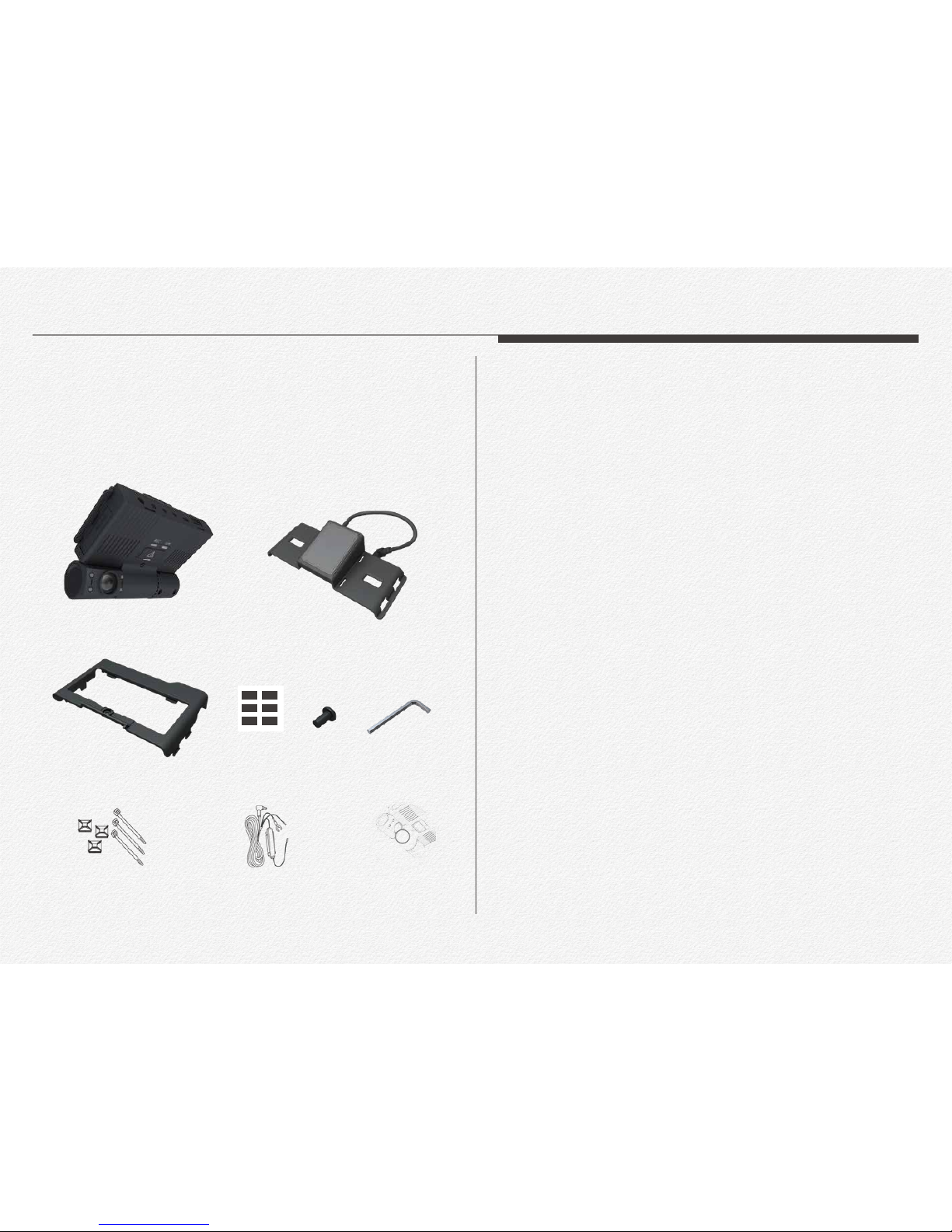
Your network drive recorder comes with the accessories shown
on this page. If any of these items is missing from your box, call
customer center.
* The exact appearance of each item may vary by model.
* Micro SDXC memory card are not included.
* You can purchase parts and accessories after consulting with
your local distributor. Product is not responsible for reduced
malfunctions caused by any unauthorized use of accessories
such as the power cable etc.,
* The exact appearance of each item may vary by model.
Section 1
Unpacking
Main NDR
GPS Module & Cradle
Tamperproof cover Screw seal Screw Screw wrench
Cable Clip & Tie Uninterrupted power cable CD
9
Section 2
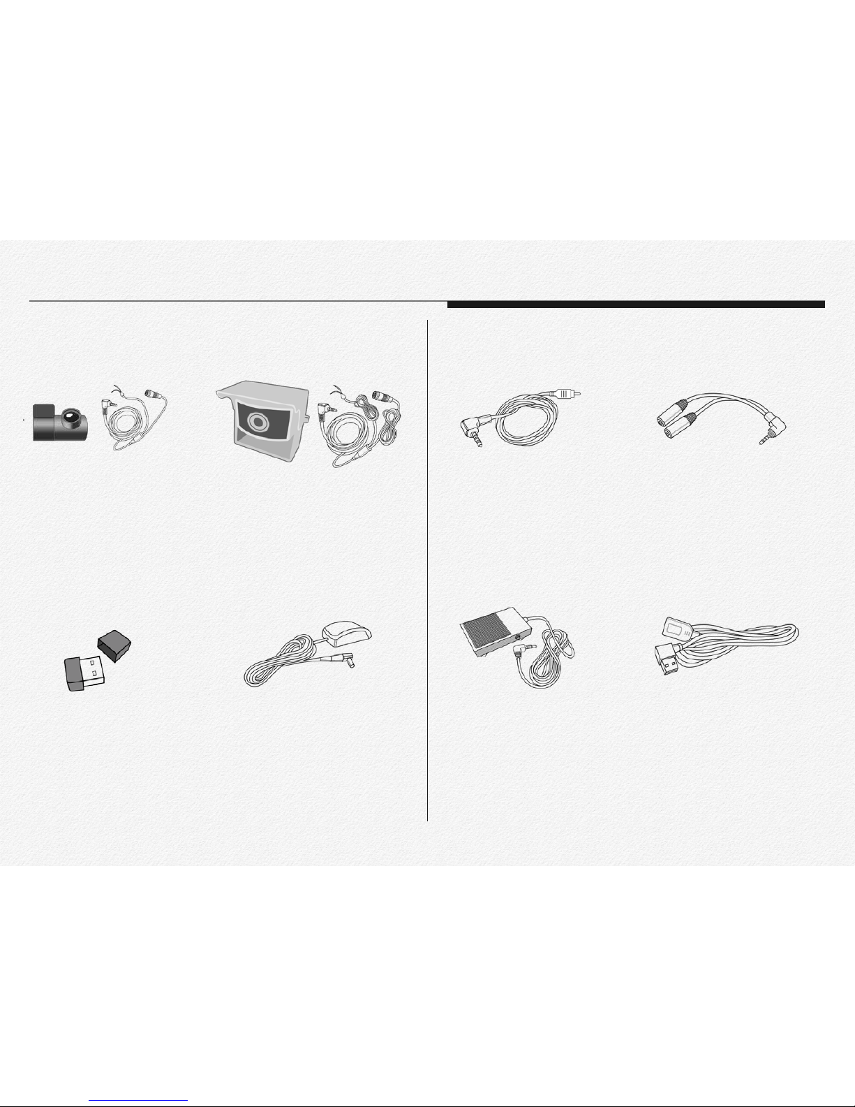
Optional Accessories
FPRO-RCM
3rd Camera
* 720x480p
* 6 meters cable
* Reverse gear signal wire port
* DC 5V power use from NDR
* Korea origin
* 720x480p / IP67 / Waterproof
* 160(D) wide angle / IR LED
* 23 meters cable
* Reverse gear signal wire port
* DC 5V power use from NDR
FPRO-RCO
3rd Camera
* IEEE 802.11 b/g/n
* 2.4GHz frequency bands
* OFDM, Peak rate 150Mbps
* Peak throughput 90Mbps.
* 64/128 WEP,WPA,WPA2,TKIP,AES
FPRO-WIFI
Wireless LAN USB Adaptor
* IP67 / Waterproof
* 6 meters cable length
* Magnetic type
* MCX connecter
FPRO-GA8
External GPS Antenna for
metal film coating vehicle.
* 2.5mm EarPhone jack to RCA
* 3 meter cable length
* UL approved
FPRO-VOC
Video-out Cable
* 2.5mm EarPhone jack type
* 1 male to 2 female jack use
* This part is may need to use video-out
cable and panic button use at once
FPRO-YC
Y-Type Cable
* IP54 / Metal type
* 5 meters cable length
* 10A/250VAC
* This part is able to connect to
Video-out port from NDR
FPRO-EFS
Panic Foot Switch
* L-angle male to right angle female
* Use for external flash memory
FPRO-USBL6
USB 2.0 Cable
10
Section 3
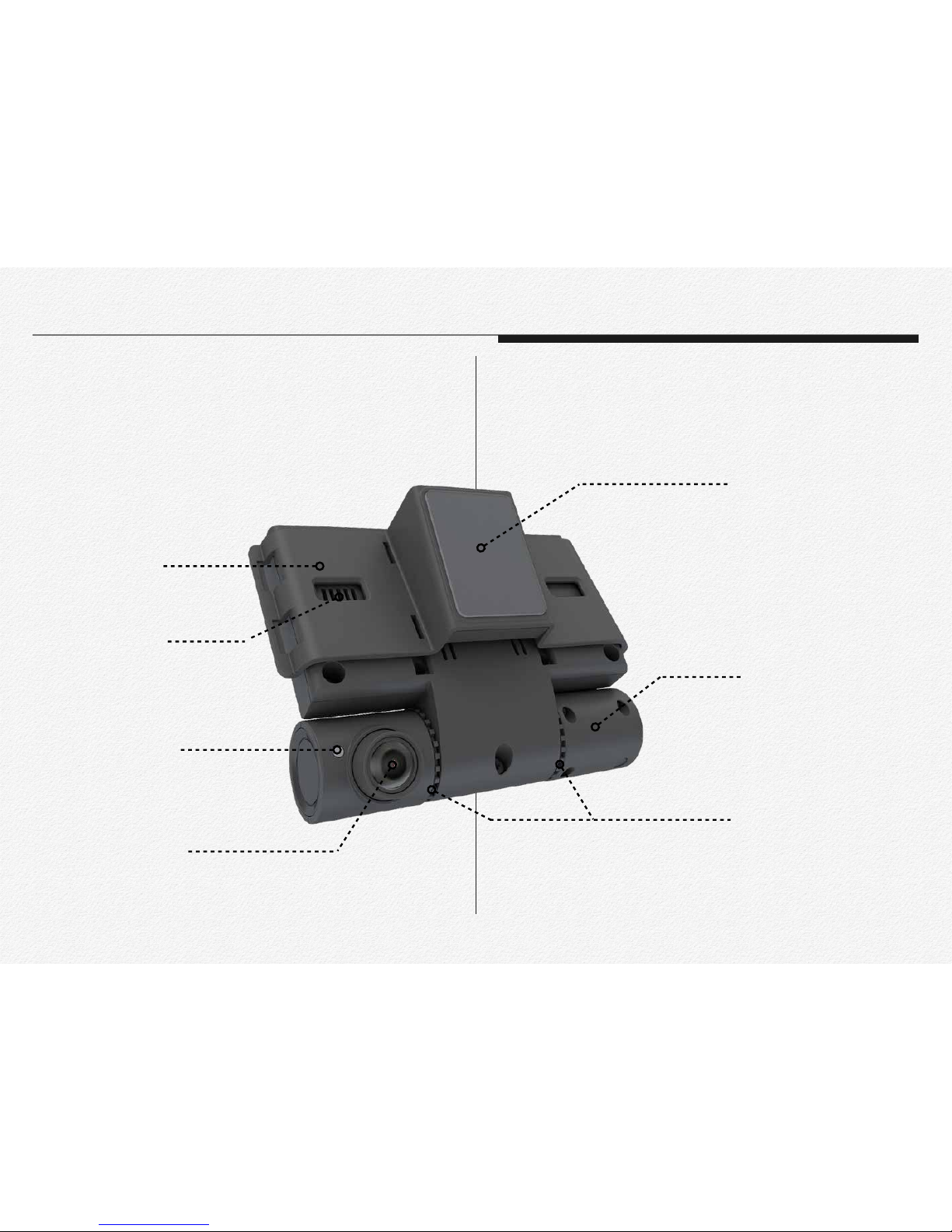
Part & Names
Read this section to learn about the NDR features, how to use the controls, and more.
GPS & Cradle
Operating LED
Road view camera
(Six-element lens)
GPS receiver module
(GNSS worldwide)
In-cabin view camera
Angle hook for tamperproof case
Speaker
Main device-Road side view
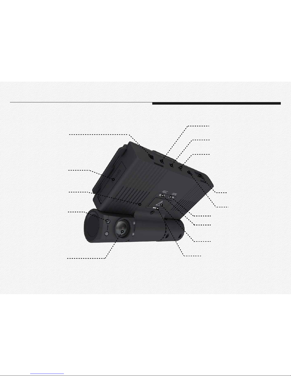
In-cabin view camera
(Six-element lens)
In-cabin IR LEDs
(Infrared night vision
recording)
Micro SD card slot
(Dual slot)
DC power
GPS port
Video-out port
3rd camera port
USB 2.0 port
Micro USB port
Network state LED
Record state LED
GPS state LED
Manual event recording button
Microphone and
Reset button
Main device-InCabin side view
In Cabin view
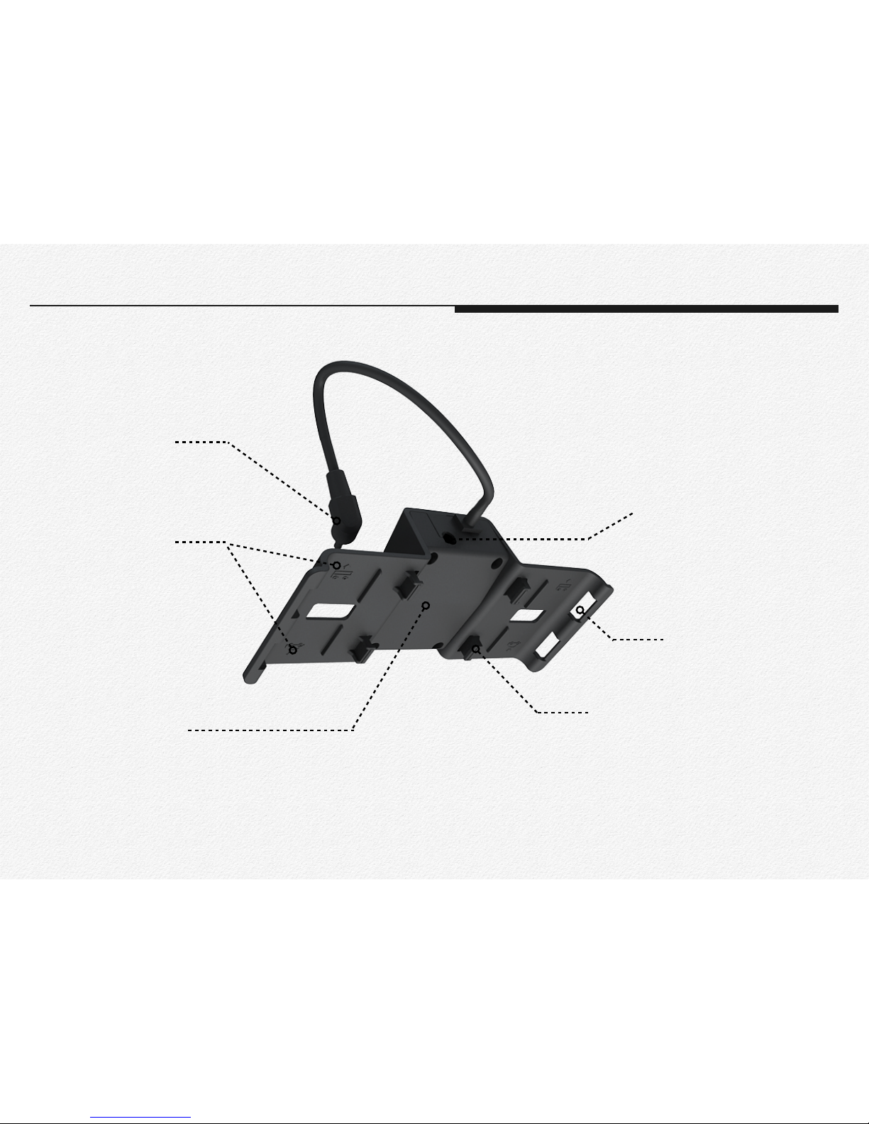
12
GPS cable jack
Install type assignment icon
External GPS antenna MCX
connecter
Main device joint hook
Tamperproof cover hook
GPS Receiver module inside
GPS & Windshield cradle
GPS & Cradle
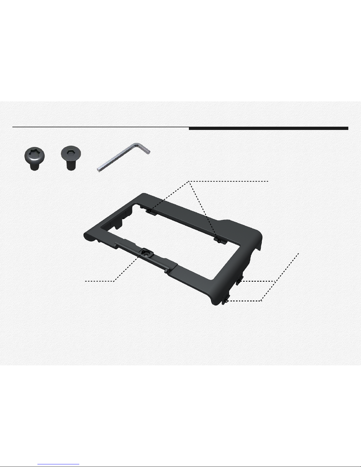
Main device joint hook
Lock screw joint hole
GPS Cradle joint hook
Tamperproof cover
Tamperproof cover
Star shape Hexagon shape
Screw Wrench
* option
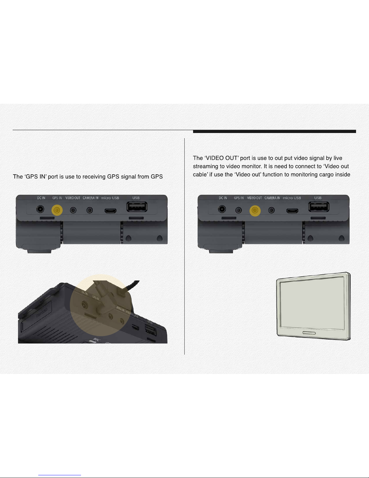
14
GPS IN
module receiver.
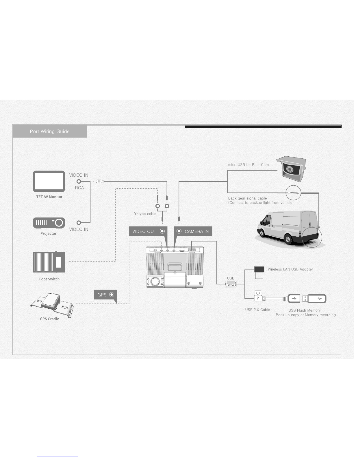
VIDEO OUT
or backward view.
Section 4
Terminal ports

15
switch. And If need to use for video out and panic button switch
at once then it is able to connect by Y-type cable use.(Extra)
CAMERA IN
power DC 5v to 3rd camera and able to receive analog signal
for reverse gear detection or electronic dry signal from 3rd
Video monitor (RCA) SOS Panic foot S/W
Y-type cable
VIDEO OUT
3rd Camera
Dry signal cable
(High & Low)
CAMERA IN
16
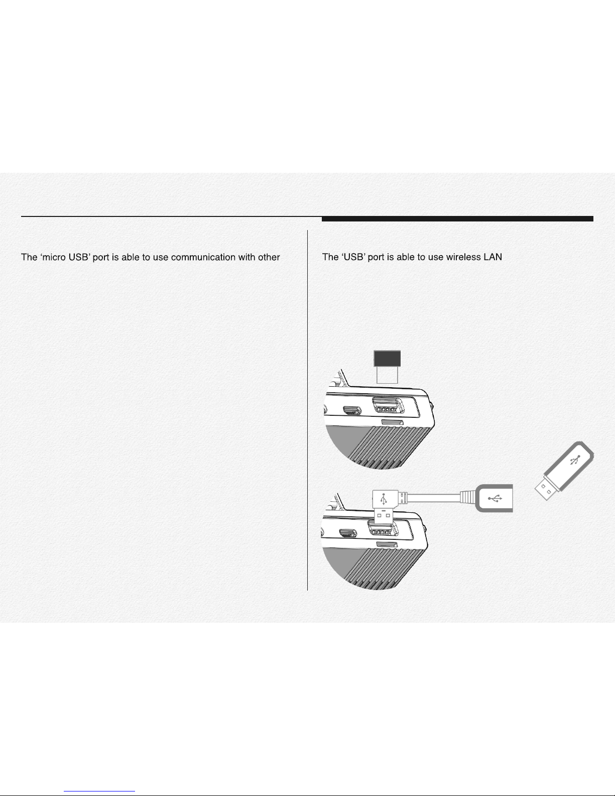
MicroUSB
devices for record and save to external hard drive(SSD/HDD)
or charging battery for smart phone or pocket Wi-Fi modem
use for a long time etc. The port is supplying DV 5v power to
connected device. (Host mode)
USB
USB adaptor or
3G/LTE USB modem for telematics server transmission and
the port is support to record and save at external removable
flash memory back up automatically or charge to battery for
smart phone or pocket Wi-Fi modem use for a long time etc.
The port is supplying DV 5v power to connected device. (Host
mode)
Wireless LAN USB adaptor for internet access
Back up and save data to external
device(SSD/HDD/Flash memory)
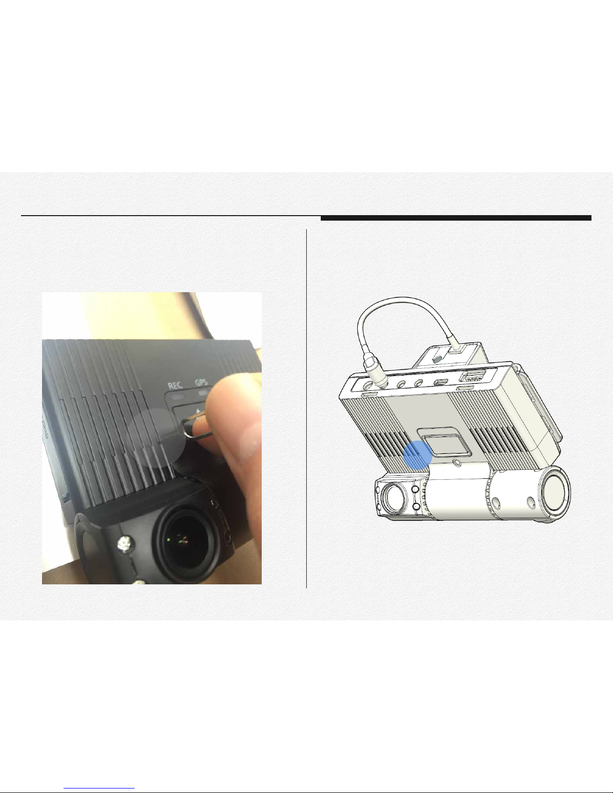
17
Reset button
When the NDR is freezes or hold operating then makes reset
power by push reset button.
Microphone(MIC)
Microphone is located beside of reset button hole.
All the devices are must be connected to each port before supply the power to main NDR.
Please read this chapter for
basic operation of NDR.
Getting ready to start recording
20
* You can use micro SDHC, and SDXC cards with this network
drive recorder. We recommend you use an micro SDHC,
SDXC card. This drive recorder supports SDHC, SDXC cards
up to 128GB. We cannot guarantee normal operation with
SDHC cards bigger than 128GB.
* MMC (Multi Media Card) and MMC Plus are not supported.
* Compatible memory card capacity:
- SDHC: 4GB ~ 32GB
- SDXC: ~ up to 128GB
* When you use unauthorized memory cards, the driving re-
corder can not record videos correctly and your recordings
may be lost.
* The memory cards released after this drive recorder was re-
leased may not be compatible with the network drive recorder.
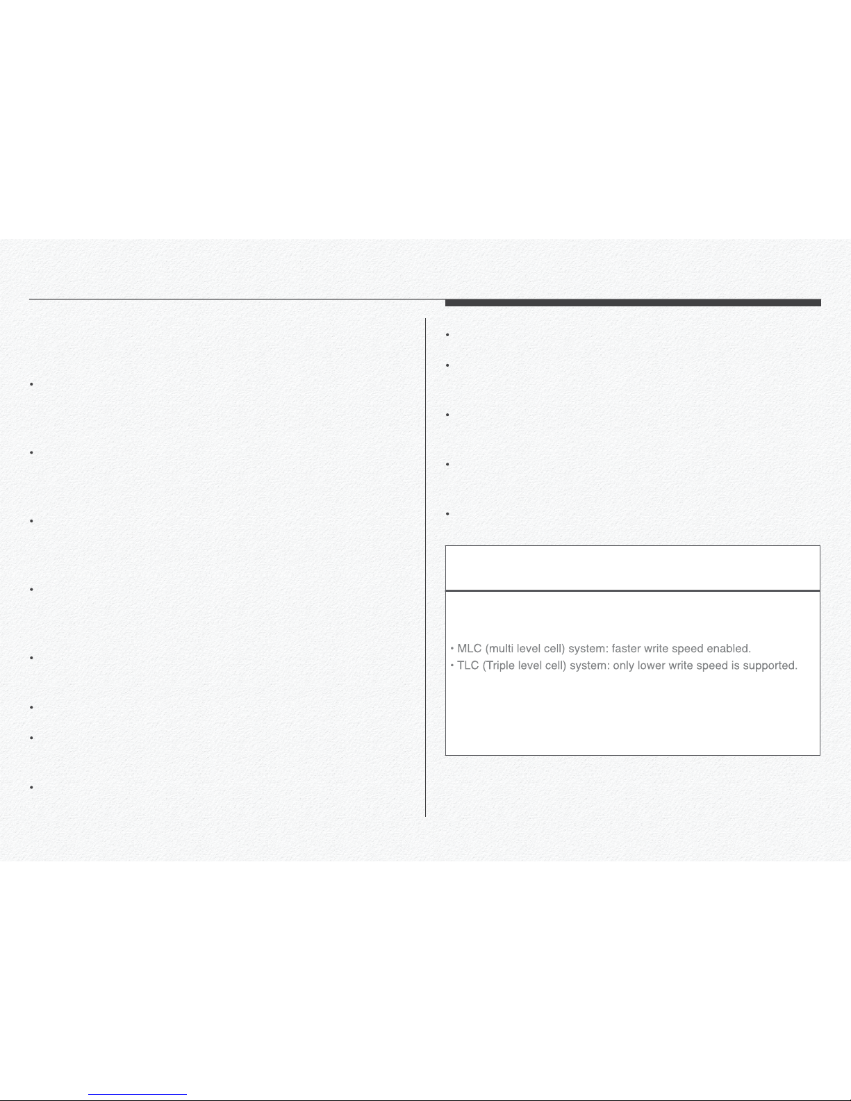
* To ensure stable recording and playback, use writing speed
40MB/s (Class 10) or higher memory cards. (MLC/Multi Level
Cell) Type memory card is recommended)
* SDHC/SDXC cards are a higher version of micro SD memory
cards and support higher capacities than micro SD memory
cards.
Section 1
Selecting a suitable memory card
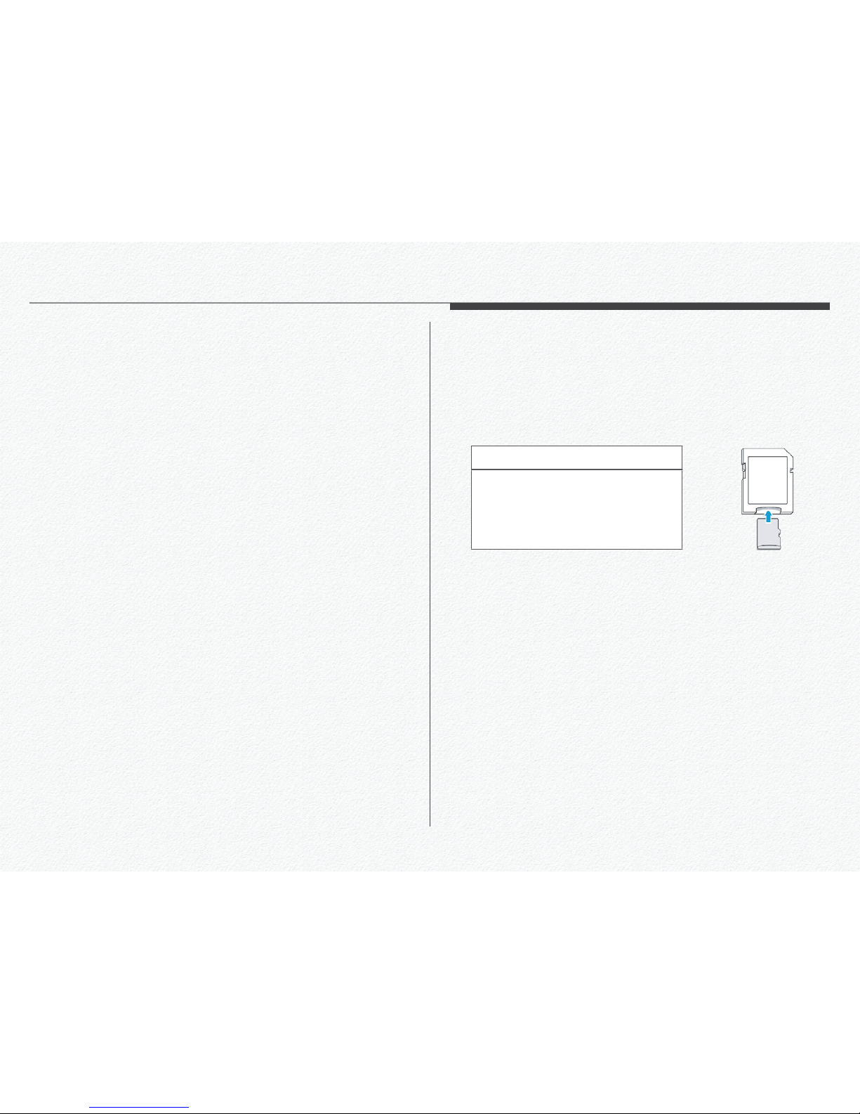
Using the memory card adaptor
To use a micro memory card with a
computer or card reader you must
attach it to or insert it into an adaptor.
21
Damaged data may not be recoverable. We recommend you
make a back-up of important data separately on the hard disk
of your PC.
Turning the power off or removing a memory card during an
operation such as formatting, deleting, recording, and playback may cause data loss.
If you modify the name of a file or folder stored in the memory
card with your PC, your NDR may not recognize the modified
file.
The memory card does not support any data recovery mode.
Therefore, care should be taken to prevent the memory card
from being damaged while recording.
A memory card has a certain life span. If you cannot record
new data, you have to purchase a new memory card.
Do not bend, drop, or subject the card to strong impacts.
Do not place foreign substances on the memory card terminals. Use a soft dry cloth to clean the terminals if required.
Do not paste anything other than the label provided with the
card on the label pasting area of the card.
Do not use a damaged memory card.
Be careful to keep the memory card out of the reach of children, who might swallow it.
We are not responsible for data loss due to misuse, including
loss caused by any PC virus.
We recommend using a memory card case to avoid data loss
that can be caused by moving the card or by static electricity.
After a period of use, the memory card may get warm. This is
normal and is not a malfunction.
The NDR supports micro SDHC, and SDXC memory cards, giving
you a wider choice of cards!
The data storage speed of cards may differ, depending on the
manufacturer and production system.
For best results, we recommend using a memory card that
supports a faster write speed 40MB/s or higher.
Using a lower write speed memory card for recording video may
cause difficulties when storing.
Section 2
Handling a memory cards
22
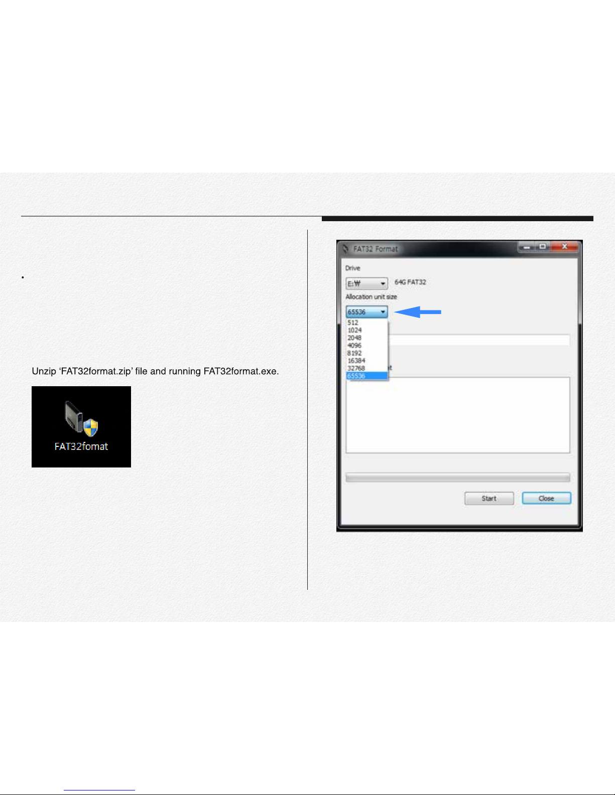
Please format FAT32 before copy the firmware to micro SD
card when you need firmware update.
A. Window PC User.
1. Connect removable memory card(micro SDXC card) to PC
first.
2.
3. Select memory card unit size(Allocate unit size);
(Ex. 32GB -> 32768 / 64GB-> 65536)
Section 3
Format memory cards
Select memory size
23
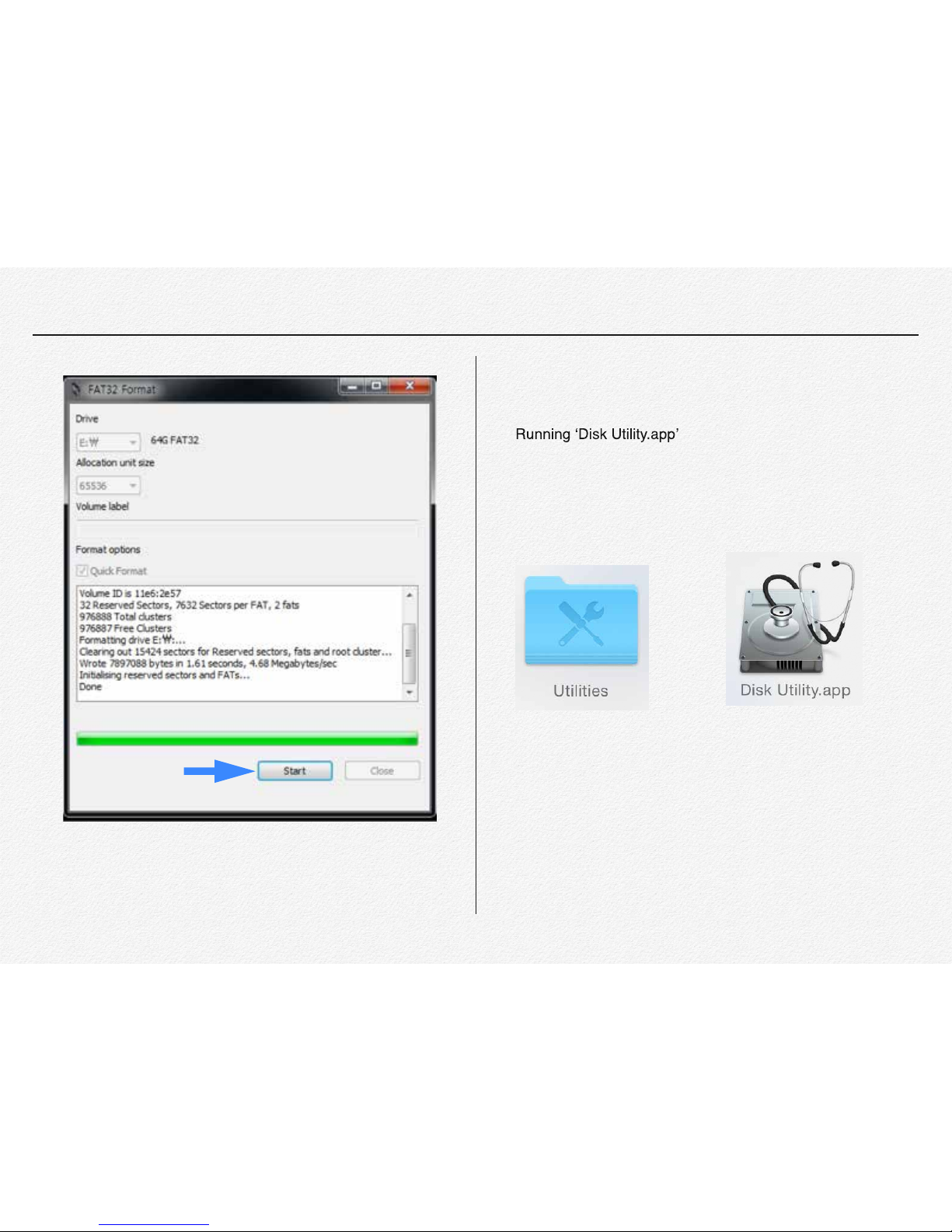
B. MAC IOSX PC User.
1. Connect removable memory card(micro SDXC card) to MAC.
2.
(Application > Utility > Disk Utility.app )
Click to start
format
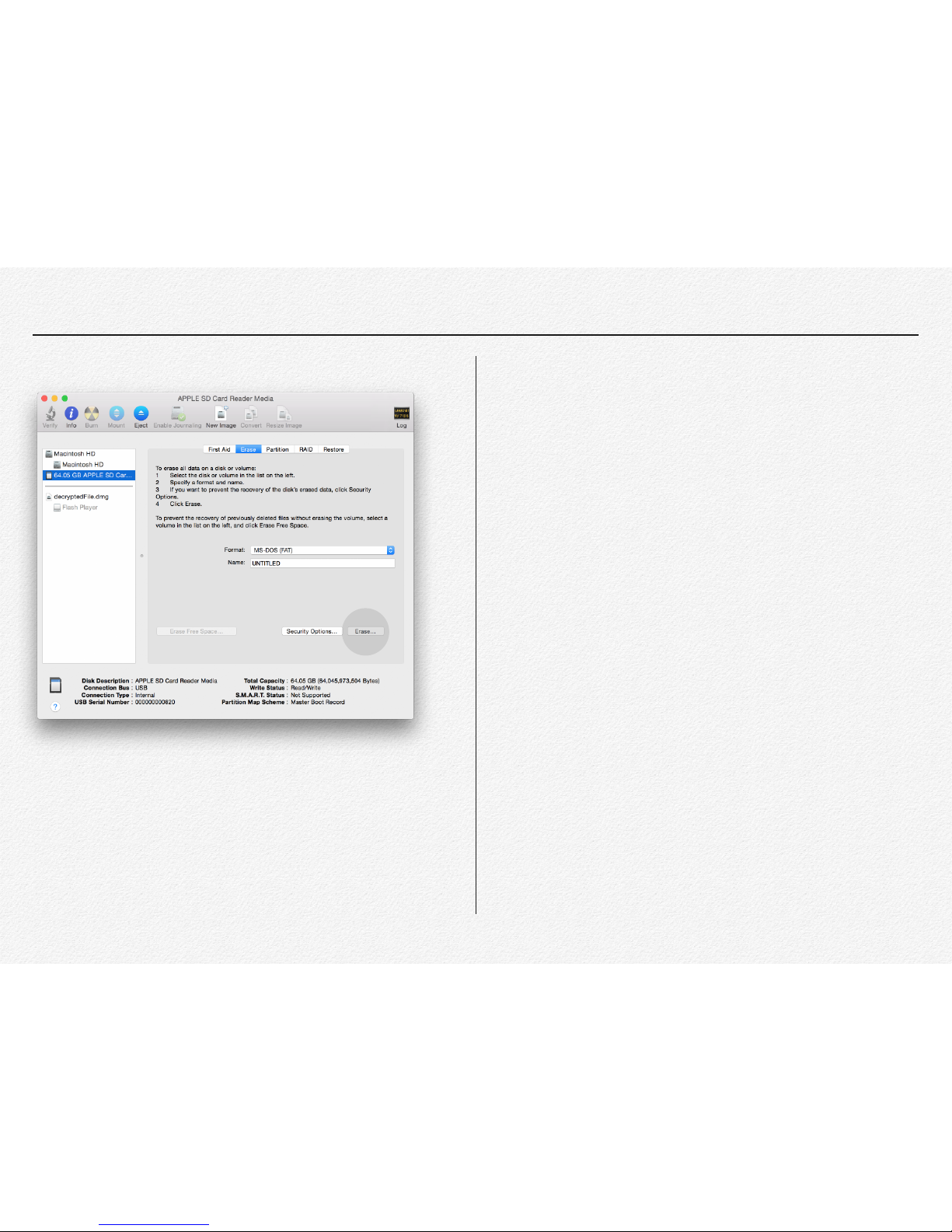
24
3. Select removable memory card erase by MS-MOS(FAT)
4. Click to Erase button.
5. Format completed.
25
A) Ready to update
1) Format micro SD card before firmware upgrade.(
page 20)
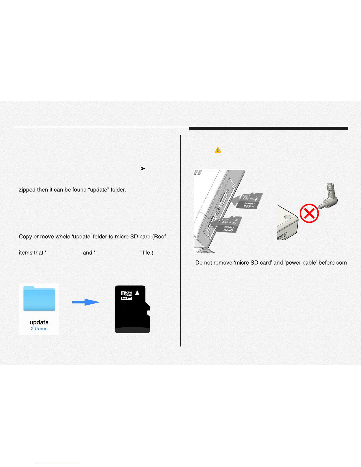
2) Unzip the firmware file as attached this file folder. After un-
B) Upgrading firmware
1) Connect micro SD card to PC.
2)
directory / the update file folder has contained two type of
ACA_FS.img ACA_ulmage.bin
3) Remove micro SD card from the PC and insert SD card to
NDR. (
Please make sure that NDR power is must turn
off state when insert micro SD card.)
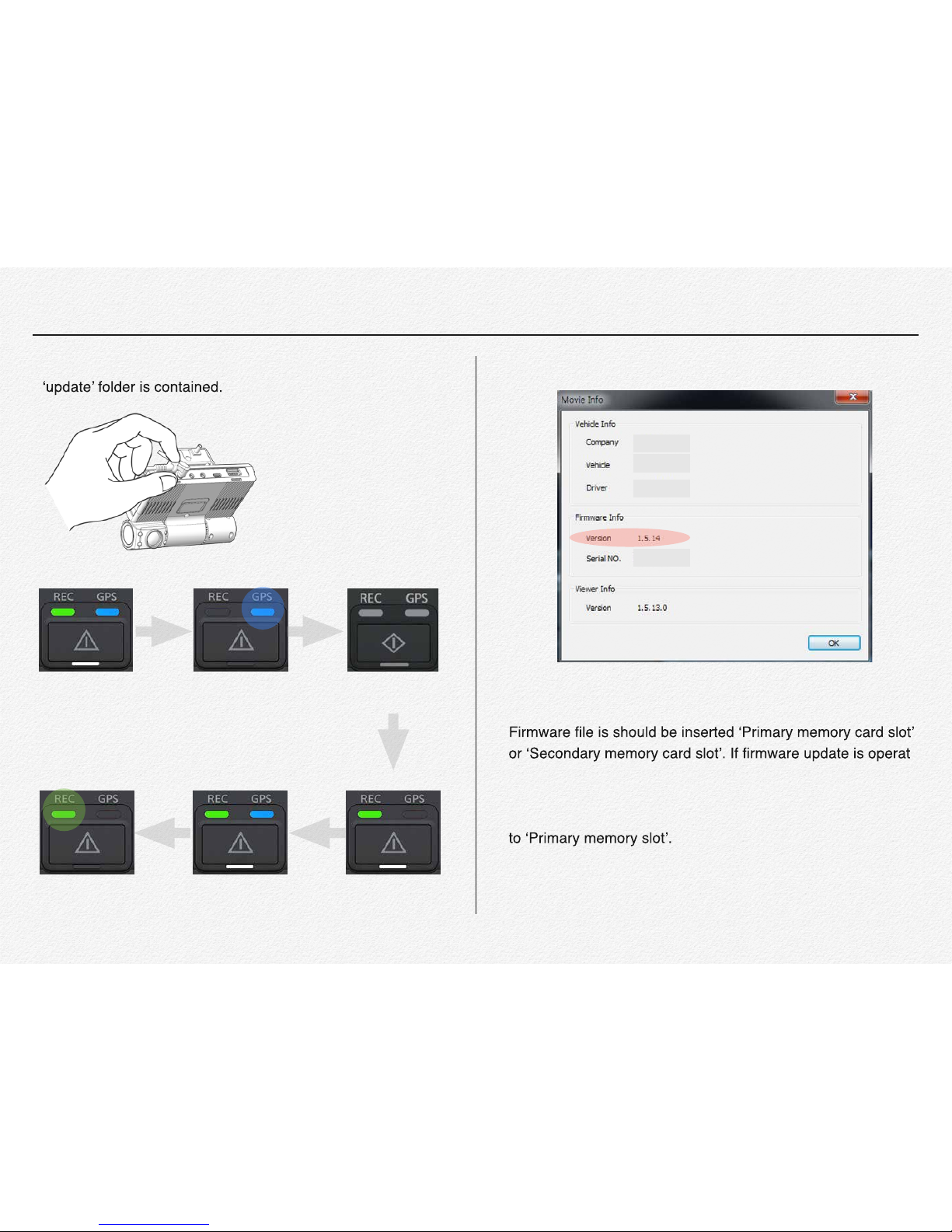
4)
-
pleted upgrade.
C) Upgrading Time
* Firmware update time will be takes around 1 minute and 30
seconds.
* The NDR system will reboot automatically after update com-
pleted. ( System reboot time will be takes around 15 seconds.)
Section 4
How to update firmware
Copy
26
* Plug in DC power cable after inserted micro SD card which * It is able to check updated firmware version via PC manager.
D) Others
*
ing via 1(one) micro SD card then no matter slot place select.
But if firmware update is operating with 2(Two) micro SD card
inserted statue then update firmware file is should be inserted
Firmware is will not be upgraded by external USB memory
device.
Power on Updating System Closing
Power on System Booting
Recording
(Completed)
Power on
27
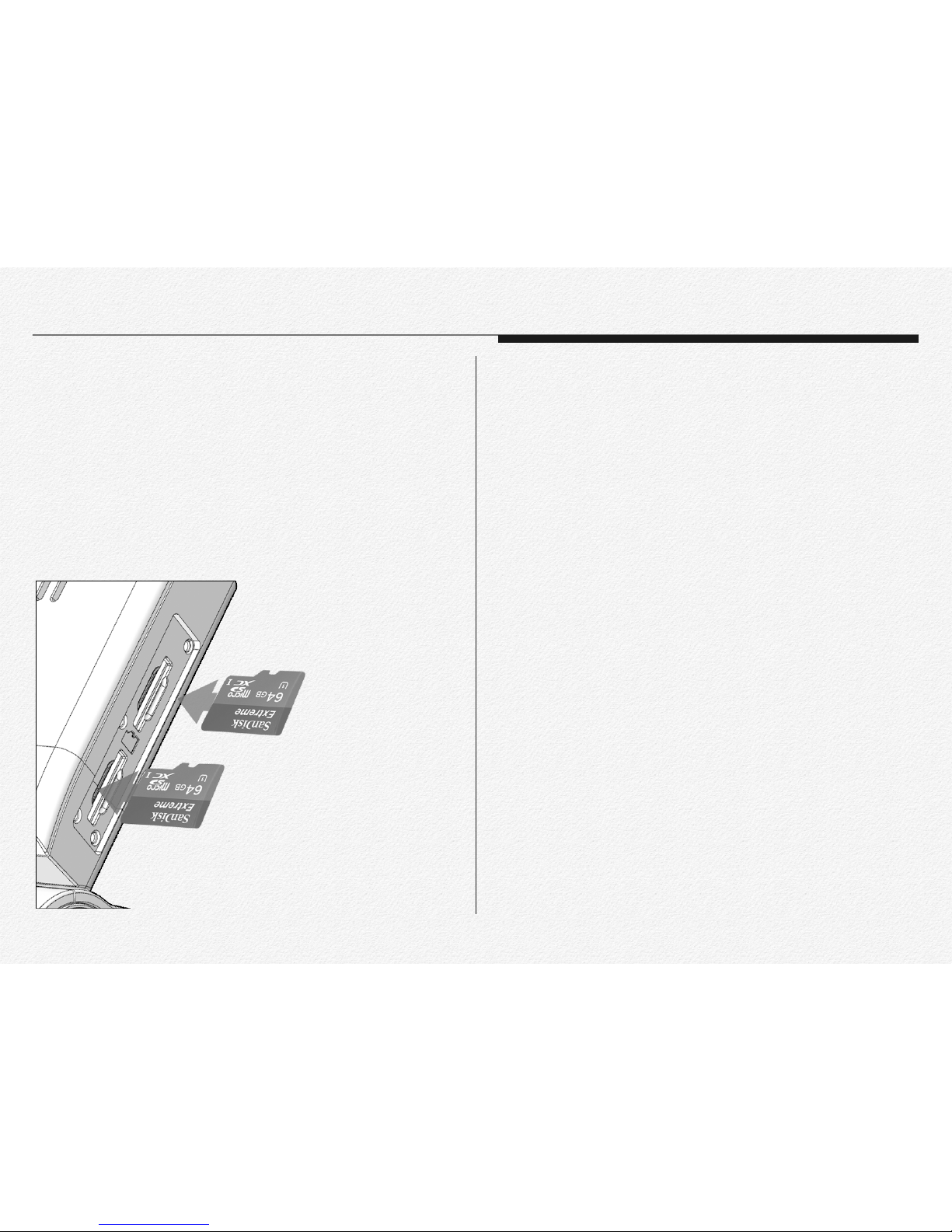
1) Insert micro SD card when NDR power off.
2) Open the memory card cover as shown the the figure.
3) Insert the micro SD card into the card slot until it softly click
of a latch. ( Make sure that the NDR is placed as shown
above and the terminal portion of the card is facing up.)
To eject a memory card
1) Turn off the NDR. (Pull off DC power jack)
2) Open the memory card cover and gently push the micro SD
card to eject it.
3) Pull the micro SD card out of the memory card slots and
close the cover.
* To avoid data loss, turn off the NDR by removed the power ca-
ble before inserting or ejecting the memory card.
* Be careful not to push the memory card too hard. The mem-
ory card may suddenly pop out.
* If you eject the memory card from the NDR while it is on, the
NDR turns off.
* Card compatibility with this NDR may vary depending on the
card manufacturer and type.
Section 5
To insert a memory card.

28
* The NDR is able to save all the data to external memory de-
vice instead of micro SD card as like SSD/HDD even flash
memory stick via micro SD or USB port use.
* The port USB and micro USB is supply power DC 5V to exter-
* When connect external device via micro USB or USB then the
NDR will not be saved the data to micro SD memory.
* If connect external device while recording to micro SD card
then the NDR will start data backup to external device from micro SD card as setup order. After completed backup tasking
then the NDR will start recording automatically.( Page 83Setup configuration)
Section 6
Connect external memory
USB / microUSB cable connection

Please read carefully for
safety install the NDR.
Installation

30
The NDR is designed that support various angle of windshield
from the vehicle. Please refer to below figure for right installation for video angle fit.
The NDR has marked direction guide as icon of vehicle type.
you can follow direction by icon as your vehicle.
Section 1
Direction of Cradle
Truck & Bus
Taxi & Sedan
For Truck & Bus
For Taxi & Sedan

31
Joint the cradle with main device
The NDR is designed that support various angle of windshield
from the vehicle. Please select and placing cradle to windshield.
Mounting the NDR
The NDR is designed that support various angle of windshield
from the vehicle.
1) Before mounting the NDR, please ensure that the windscreen is free of grease, dust and any other dirt that may re-
sult in poor adhesion. It is recommended that the wind-
screen is wiped with a glass cleaner such as Windolene or
similar.
Please refer to above tutorial movie for joint main device with cradle.
MOVIE 4. 1 Joint the cradle with main device

32
2) Remove the film on the double-sided adhesive tape.
3) Placing cradle on the windshield.
4) Insert micro SD card.(Power off statue.)
Center of windshield

33
5) Joint the main NDR with cradle.
6) Connect the cables. (All the cables are must be connected to
each port before supply the power to main NDR).
Full connected wires

34
PIN Assignment 1
3rd Camera Jack(CAMERA IN) SOS Panic Button Jack(VIDEO OUT)

35
PIN Assignment 2
Y-Type Cable Jack(VIDEO OUT) Video Out Cable Jack(VIDEO OUT)

36
Section 2
How to fit the power loom
1) The NDR is compatible DC8V~32V. The included DC fuse
power cable can be connected directly to the battery(permanent power connection for recording 24/7) or to the ignition
(the device will record only when the vehicle is on).
2) The power loom consists of a battery + and an Earth connection. The red wire will be battery + and the black wire will be
the earth connection and white wire will be the ignition(ACC)
connection.
3) Please remember that all connections must be within the tracking unit specs as per industry related connections.
4) Run the cable (power loom) via the A pillar into the roof lining
and let it meet up close to the main unit.
5) Plug the loom into the main unit and then give it a bit of slack
so that there is no tension on the power loom or the plug area
of the unit.
6) Use the management clip to tie up the cable and make if look
screen and cable tie the cable to the management clip or slide
them in the opening slots.

37
1) Adjust camera angle of view.
2) just camera angle.
3) Joint tamperproof cover with cradle clips.
Section 3
Joint tamperproof cover
Please refer to above tutorial movie for joint main device with cradle.
MOVIE 4. 2 Joint tamperproof cover

38
4) Joint and lock the screw 5) Extract tamperproof cover from NDR.
Please refer to above tutorial movie for extract tamperproof cover.
MOVIE 4. 3 Extract tamperproof cover

5
The NDR has LED lamps
for operating signals.
LED Signals

40
System boot
The LEDs are indicate system operating state.
Update setup file
The LEDs are indicate that setup configuration
value.(Setup.cfg)
GPS signal detection
The LEDs are indicate that receiving GPS signal.
Section 1
LED Signals
Power on
System booting Recording
This LED signal is normal start state NDR.
MOVIE 5.1 LED State of system boot
Reading setup file.
Recording
Receiving GPS signal (Blue LED hold)

41
LED Signal table USB Backup
When it completed backup USB then Green and Blue LED are
blinking at once. The NDR is not recording and save the
video file to micro SD card while backup to USB.
Operating LED Operating LED
gnitooB metsyS
(Approx. 5sec.)
Connecting
External Device
gnitoob-eR
(Approx. 20sec.)
Not inserted
memory card
Firmware
updating
(Approx. 40sec.)
GPS signal
detected
Normal
Recording
Event Recording
(Approx.15sec.)
USB Backup
USB Backup
completed
Blinking
Just remove to connection after completed data backup to external
USB memory or HDD.
MOVIE 5. 2 USB backup LED state.

42
Firmware update
After completed firmware update then the NDR will reboot system and start recording in automatically.
Remote download Firmware(OTA)
After download firmware via wireless network then the NDR will
update and reboot in automatically. This OTA function is based
on FMS Network service approved.(Option) Please contact to
your distributor to use OTA function and FMS service.
MOVIE 5. 3 LED state of Firmware update
The NDR is keep recording and save the video data while OTA firmware
downloading.
MOVIE 5. 4 LED state of OTA firmware downloading

Features

44
Encryption Video
The NDR is designed secure video data. It is unable to playback via common media player except by use private PC man-
3rd Camera Recording(Extra)
It is able to use 3 Channels recording by connecting optional
rear camera or dome camera for 3 Channels video recording.
The NDR is able to use DC5V 3rd camera.
3 Channel recording function is able to select setup via PC manager.
Section 1
Features-NDR
2 Channel
3 Channel

45
Video resolution as channel selection.
Back-up gear signal cable
When connect the back-up gear signal cable to back-up light or
view to video monitor.
IR Recording
Providing a brighter video and picture, wider view, and longer range
in low-light situations, the NDR
cameras use the latest night vision
technology to surpass expectations for quality video even in the
dark.
In-Cabin camera with 4(four) IR_LED are automatically turns
ON and OFF according to surrounding luminance. If closer object in front of In-cabin lens then IR LED lamps will turn and off
repeat, this is normal and is not a malfunction.
Cycle Recording
During normal operate the video files are saved in 60 second
intervals. If the capacity of the micro SDHC card runs short, the
files will be overwritten from the oldest to newest.
EMERGENCY files will not be overwritten. (factory default). It is
able to be changed configuration via PC manager setting.
2 Channel Resolution Bit-rate fps/sec.
Front Ch. 1280x720p 4Mbps 30 fps
In-Cabin Ch. 1280x720p 4Mbps 30 fps
3 Channel Resolution Bit-rate fps/sec.
Front Ch. 1280x720p 4Mbps 30 fps
In-Cabin Ch. 1280x720p 2Mbps Max 15 fps
3rd Ch. 720 x 480p 512kbps Max 15 fps
Back-up gear signal wire.
Do not connect the back-up
gear signal wire to any power
output port. It may cause product failure.

46
Video out(Monitoring)
The NDR provides a CCTV interface for real-time video monitoring from the drivers seat. Single and multi-view options are selectable and the device can output the 3rd camera video signal
automatically when the vehicle has signal. User is able to select
4 type of video out display mode.(
Page.14)
Input External Trigger
The NDR is able to receiving and sending trigger signal or data
via micro USB port. some features are may needs to customize
for software as requirement.
LBP(Low Battery Protection)
The NDR is able to setup cutoff voltage and timer for protecting
the discharge of the battery of vehicle. And multiple power control options allow recording to start and stop using vehicle ignition, delayed system shutdown and/or preset ON/OFF times.
(DC 11.8V,12V,23.7V,24V)
Voice Guide & Alarm
The NDR has voice guide via internal speaker for several international language. The driver is able to recognize operating
situation as working and several alarms.
Sound Recording
The NDR is able to setup sound recording enable to use or not.
Front In-Cabin
Front & In-Cabin
1) 3rd Camera always
2) 3rd Camera while back-up
signal detected.

47
Video Overlay
The video image is contain the information about time and location even have driver information. In case of information that the
driver and company name with number plate of vehicle.
①
⑨
②
③
④ ⑤
⑥
⑧
⑦
[ Figure 6.1.1] Information of overlaid on the front video
Location Descriptions
① Camera View
② Time Information
The time information is selected by configuration
[Case 1: Only RTC is overlaid]
RTC[YYYY:MM:DD-HH:MM:SS]
[Case 2: Only UTC is overlaid]
RTC[YYYY:MM:DD-HH:MM:SS]
[Case 3: RTC & UTC are overlaid]
RTC[YYYY:MM:DD-HH:MM:SS]
UTC[YYYY:MM:DD-HH:MM:SS]
[Case 4: RTC with Daylight Saving Time]
DST[YYYY:MM:DD-HH:MM:SS]
③ GPS Coordinates
If the NDR will not be received GPS data then
④ G-Sensor
Each value is displayed up to the decimal point
second place. The section shows procedures
regarding X-axis value Gx, Y-axis value Gy and
Z-axis value Gz.
⑤ Sum
This value is total sum about G-sensor
⑥ Speed
This value is receiving from GPS signal.
(Km/Mph/Knot per every 0.5 seconds)
⑦ Company name
⑧ Driver name
This value is able to setup by PC manager
⑨ Vehicle number
This value is able to setup by PC manager

48
①② ①②
[ Figure 6.1.3] Information of overlaid on the 3rd camera video
Location Descriptions
① Camera View
② Time Information
The time information is selected by
[Case 1: Only RTC is overlaid]
]SS:MM:HH-DD:MM:YYYY[CTR
[Case 2: Only UTC is overlaid]
]SS:MM:HH-DD:MM:YYYY[CTR
[Case 3: RTC & UTC are overlaid]
]SS:MM:HH-DD:MM:YYYY[CTR
]SS:
MM:HH-DD:MM:YYYY[CTU
[Case 4: RTC with Daylight Saving Time]
DST[YYYY:MM:DD-HH:MM:SS]
[ Figure 6.1.2] Information of overlaid on the In-Cabin video

49
Data Logs
The NDR is recording log history data about Accident event and
G-Sensor and GPS by CSV file format. This log file folder will
Logs data has contained below data
Log File Name Contained data
Accident-event-log
Event Type, File name, RTC Date & time,
UTC Date & time, GPS signal state, Latitude,
Longitude, Direction(N.S.E.W), Speed value,
,eulav )MUS kcehC,Z,Y,X(rosneS-G
Back-up dear state
G-SENSOR
RTC Date & Time, UTC Date & Time, GSensor(X,Y,Z,Check SUM) value per every 0.5
seconds interval.
GPS
RTC Date & Time, UTC Date & Time, GPS
signal valid, Latitude, Longitude, Direction,
Speed, Check SUM.
Accident-event-log file
G-Sensor log file

50
Manual Event Recording
This enhanced feature enables an additional method for triggering Event Alarm Video for a specific incident to be recorded for
quick, future review. And built-in LED
status light will indicate the system is
functioning properly.
SOS Panic Button Recording(Extra)
Panic button(Hidden button) push. The video file will be stored
and after 15 sec.) And If the NDR has connected network then
SOS signal will be transmitted to Administrator.
Excessive Speed Trigger
Combined with the GPS, the NDR can be stored speed event
alarm video when the vehicle exceeds a preset speed.
Motion Detection - Sleep mode
Under motion detective when it entering sleep mode(park
mode) the NDR will automatically start recording when any object movement is detected. The NDR can be setup to enter
space.The built in motion sensor will cause the NDR to resume
GPS log file
Manual Event Recording Button
Sleep mode is not recording and save any video file instead of monitor-
onds( before event 15 sec. and after 15 sec.) when it detected any object
movement and back to the sleep mode again in automatically.

51
GPS(GNSS)
location and speed. Use the included the NDR PC Manager
and your video will also display with an integrated GPS map.
The GPS will also enable the use of the systems max speed setting to trigger event alarm video when a selected speed is
achieved.
External GPS Antenna(Extra)
This optional GPS antenna is useful for metal film coated vehicle. Metallic coating on windshield of vehicle may cause signal
trouble in GPS signal.
Map Tracking
Review route efficiency and safety with available synchronized
GPS mapping and tracking embedded within the NDR.
G-Sensor
* The direction of X-axis is an advancing direction of vehicle.
* The direction of Y-axis is a horizontal direction, whose positive
.elcihev eht fo noitcerid gnicnavda ot evitaler noitcerid
* The direction of Z-axis is a vertical direction, whose positive
direction is a downward direction.
X-axis
Z-axis
Y-axis

52
Driving Report
It is able to print out driving report or save PDF file format to
sending secure email. The report has contained below items.
Driver name, Vehicle number, Company name, Driving date &
speed, Video file name, Location address and map.all the video
snapshots.
Outpu t Power DC5V
Micro USB and USB terminal is output DC power 5V for smartphone or other USB device use. If vehicle has pocket Wi-Fi modem then it is able to charging battery by USB/micro USB terminals.
External Memory Storage(Extra)
The NDR is able to use external hard drive or SSD instead of
micro SD card use via micro USB and USB terminal. The NDR
will not be saved video file while use HDD.
Wi-Fi LAN USB Adaptor (Extra)
The NDR is able to connect wireless internet by Wi-Fi LAN USB
adaptor. (Hotspot, Tethering, AP mode Wi-Fi..etc)
3G/LT E USB Modem(Extra)
The NDR is able to use 3G/LTE modem for network communication. The NDR is support below products modems(Firmware version 1.5.16)
1. HUAWEI E8231 Wingle / Model: E8231s-2
2. Vodafone 3G / Model: K4607-Z USB Stick
3. Vodafone Mobile L4607-Z

3G/LTE Telecommunications
The NDR is able to contact to FMS/CMS server via wireless telecommunication.
GSM/3G/4G
Administrator
INTERNET WEB SERVER PC Manager
*
Live GPS Tracking
*
Real-time streaming
*
VOD Download
*
Snapshot download
*
Analysts driving data
*
Analysis driving data
*
Conguration setup
*
Information setup
*
Print out report
*
Password setup
*
Log data(Location,Speed,G-force,Event,Driving info. etc.)
*
jpg image / Motion JPEG
*
Accident VOD
3G Modem
(USIM)

Internet Telecommunications
The NDR is able to contact to FMS/CMS server via wireless telecommunication.
Pocket Wi-Fi Hotspot
Tethering
Free Wi-Fi
Internet/GSM/3G/4G
Administrator
INTERNET WEB SERVER PC Manager
*
Live GPS Tracking
*
Real-time streaming
*
VOD Download
*
Snapshot download
*
Analysts driving data
*
Analysis driving data
*
Conguration setup
*
Information setup
*
Print out report
*
Password setup
*
Log data(Location,Speed,G-force,Event,Driving info. etc.)
*
jpg image
*
Accident VOD

File & Memory Structure

56
The NDR prepares 4 types of directories and system margin
area in Primary SDHC and Secondary SDHC slot.
Directory of NORMAL File Area
This NORMAL folder is includes all non-alarm and event video
file.
Allocate 84% in primary SD Memory, 95% in secondary SD
memory.
-
MAL movie area.
When movie files reached full capacity of NORMAL movie file
area in one SD memory, The NDR starts to store NORMAL
movie files in NORMAL movie file area of another SD memory.
When it reached full capacity of NORMAL movie area in both
SD Memories, The NDR should overwrite all-time movie files
in this area (delete the oldest file and store the new file).
The EMERGENCY Event file is store in this area with sepa-
Directory of EVENT File Area
Allocate 10% in primary SD memory.
The NDR stores the accident 30 seconds movie file in EVENT
file area.
Section 1
Usage of Memory
Secondary Slot
Primary Slot
Primary memory Secondary memory

57
Although the NDR depletes capacity of Event Move File area
in primary SD, the NDR will overwrite EVENT Movie files
stored in the area. When this case occurs, even if EVENT occurs the NDR must not record new EVENT Movie file in Event
Movie File area of primary SD.
The NDR is record file names of Accident-Event-Log files to
CSV format.
The PARK Event file is store in this area with separated folder
Directory of LOG File Area
Allocate 1% in primary SD memory and Event Logs and Sensor Logs will be stored in this area.
A GPS Log is up to 1MB. If this log file becomes 1MB, the
NDR should close this log file and open new log file to record
GPS data continuously.
The NDR is stores G-Sensor data detected by the NDR in
20[Hz] as G-Sensor Log by CSV format.
A G-Sensor Log is up to 1MB. If this log file becomes 1MB,
the NDR should close this log file and open new log file to record G-Sensor data continuously.
It is able to customize each file area by setup configuration.
* If one SD memory was inserted in only Primary SD memory
slot of NDR then It operates according to the allocation of Primary SD slot.
* If one SD memory was inserted in only Secondary SD mem-
ory slot of the NDR then It operates according to the allocation
of Primary SD slot. NORMAL movie file area and EVENT
movie area are prepared in the SD memory.
Primary Memory Area Secondary Memory Area
84%
NORMAL
EMERGENCY
EVENT
LOG
System Margin
10%
1%
5%
NORMAL
System Margin
95%
5%

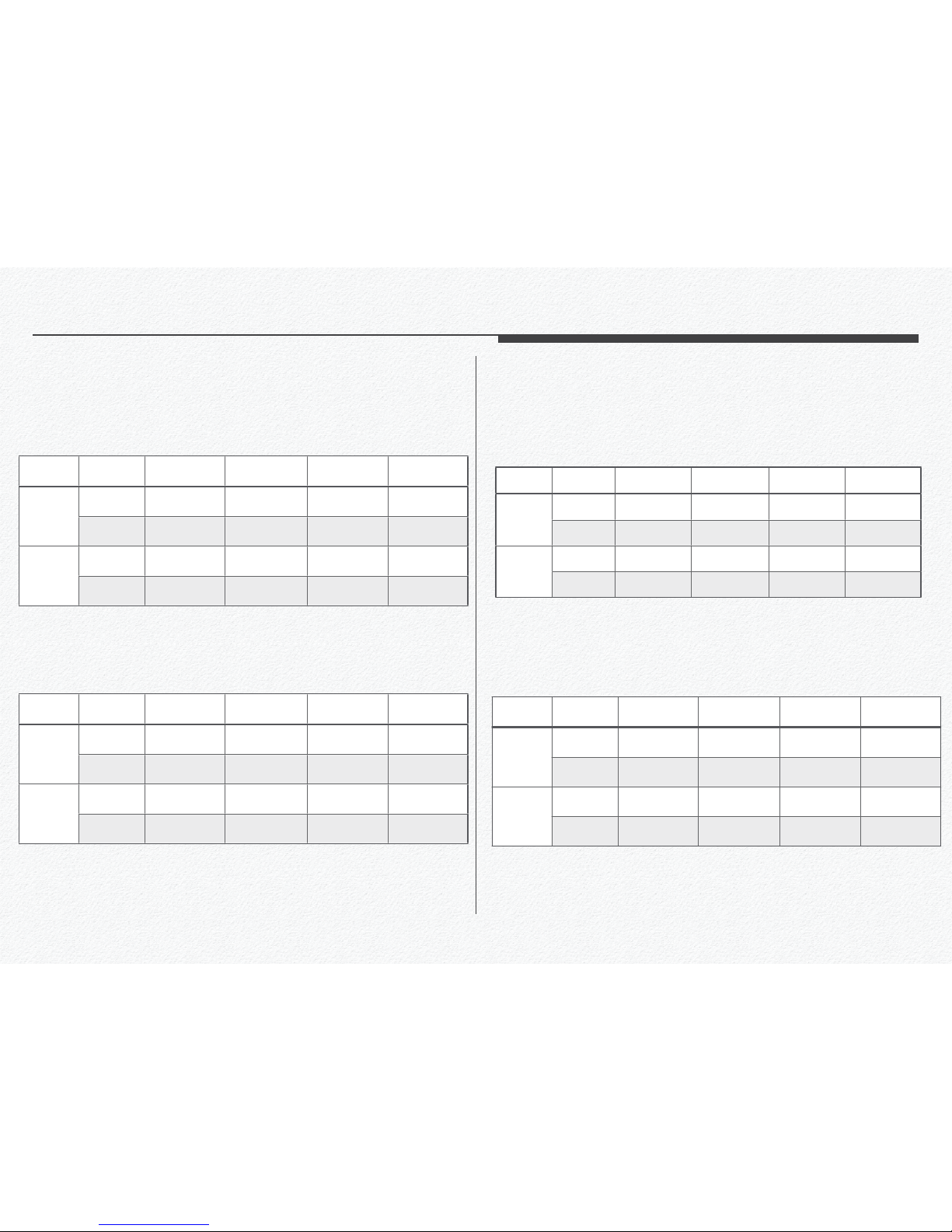
58
Recorded File Size
Recordable Time - 2Ch.
Section 2
Recordable Time and Capacity
Audio Video 4fps 5fps 10fps 15fps 30fps
Normal 10 MB 12 MB 22 MB 32 MB 62 MB
ON
High 14 MB 17 MB 32 MB 47 MB 92 MB
Normal 4 MB 9 MB 20 MB 29 MB 59 MB
OFF
High 6 MB 14 MB 30 MB 44 MB 89 MB
2 Channel mode
Audio Video 4fps 5fps 10fps 15fps 30fps
Normal 9 MB 10 MB 19 MB 27 MB 52 MB
ON
High 12 MB 14 MB 26 MB 39 MB 75 MB
Normal 7 MB 8 MB 16 MB 24 MB 49 MB
OFF
High 10 MB 12 MB 24 MB 36 MB 72 MB
3 Channel mode
Video Audio 16 GB 32 GB 64 GB 128 GB
ON 4.1 hours 8.2 hours 16.3 hours 32.7 hours
Normal
OFF 4.2 hours 8.4 hours 16.9 hours 33.8 hours
ON 2.8 hours 5.5 hours 11.0 hours 22.0 hours
High
OFF 2.9 hours 5.6 hours 11.3 hours 22.5 hours
30 fps / Secondary SDCARD
Video Audio 16 GB 32 GB 64 GB 128 GB
ON 3.6 hours 7.2 hours 14.5 hours 28.9 hours
Normal
OFF 3.8 hours 7.6 hours 15.2 hours 30.4 hours
ON 2.4 hours 4.9 hours 9.7 hours 19.5 hours
High
OFF 2.5 hours 5.0 hours 10.1 hours 20.1 hours
30 fps / Primary SDCARD
[ 2 Channel mode ]
[ 2 Channel mode ]
59
Recordable Time - 3Ch.
Video Audio 16 GB 32 GB 64 GB 128 GB
ON 25.3 hours 50.7 hours 101.3 hours 202.7 hours
Normal
OFF 31.7 hours 63.3 hours 126.7 hours 253.3 hours
ON 18.1 hours 36.2 hours 72.4 hours 144.8 hours
High
OFF 21.1 hours 42.2 hours 84.4 hours 168.9 hours
4 fps / Secondary SDCARD
Video Audio 16 GB 32 GB 64 GB 128 GB
ON 22.4 hours 44.8 hours 89.6 hours 179.2 hours
Normal
OFF 18.7 hours 37.3 hours 112.0 hours 224.0 hours
ON 16.0 hours 32.0 hours 64.0 hours 128.0 hours
High
OFF 18.7 hours 37.3 hours 74.7 hours 149.3 hours
4 fps / Primary SDCARD
Video Audio 16 GB 32 GB 64 GB 128 GB
ON 4.9 hours 9.7 hours 19.5 hours 39.0 hours
Normal
OFF 5.2 hours 10.3 hours 20.7 hours 41.4 hours
ON 3.4 hours 6.8 hours 13.5 hours 27.0 hours
High
OFF 3.5 hours 7.1 hours 14.1 hours 28.1 hours
27 fps / Secondary SDCARD
Video Audio 16 GB 32 GB 64 GB 128 GB
ON 4.3 hours 8.6 hours 17.2 hours 34.5 hours
Normal
OFF 4.6 hours 9.1 hours 18.3 hours 36.6 hours
ON 3.0 hours 6.0 hours 11.9 hours 23.9 hours
High
OFF 3.1 hours 6.2 hours 12.4 hours 24.9 hours
27 fps / Primary SDCARD
[ 2 Channel mode ]
[ 2 Channel mode ]
[ 3 Channel mode ]
[ 3 Channel mode ]

60
Your recordable time and capacity may differ from the figures
in the tables depending on your subject and actual recording
conditions.
The higher the resolution, the more memory is used.
Lower resolution increases the recording time, but the image
quality may suffer.
The bit rate automatically adjusts to the recording image. Accordingly, the recording time may vary.
Memory cards bigger than 64GB may not operate normally.
1GB
1,000,000,000 bytes : Actual formatted capacity may
be less as the internal firmware uses a portion of the memory.
4 fps / Primary SDCARD
Video Audio 16 GB 32 GB 64 GB 128 GB
ON 24.9 hours 49.8 hours 99.6 hours 199.1 hours
Normal
OFF 32.0 hours 64.0 hours 128.0 hours 256.0 hours
ON 18.7 hours 37.3 hours 74.7 hours 149.3 hours
High
OFF 22.8 hours 44.8 hours 89.6 hours 179.2 hours
[ 3 Channel mode ]
Video Audio 16 GB 32 GB 64 GB 128 GB
ON 28.1 hours 56.3 hours 112.6 hours 225.2 hours
Normal
OFF 36.2 hours 72.4 hours 144.8 hours 289.5 hours
ON 21.1 hours 42.2 hours 84.4 hours 168.9 hours
High
OFF 25.3 hours 50.7 hours 101.3 hours 202.7 hours
4 fps / Secondary SDCARD

61
has an indicator of UTC.
-
-
-
-
-
-
Section 3
File Naming Rule
Data File
Recorded Folder
NORMA
L Movie File
Movie File
EVENT
Movie File
/EVENT
EMERGENCY Movie File
Y Movie File /EMERGENCY
P
ARK Movie File
/PARK
Event Log Accident Event Log /LOG
GPS Log /LOG/GPS
Sensor Log
G-Sensor Log /LOG/G-Sensor
Recorded Folder Example of File Name
NORMAL File UTC20160726_020010.kds
EVENT File EVENT_UTC20160726_020010_E.kds
EMERGENCY File
EMERGENCY_UTC20160726_020010
_E.kds
PARK Event File PARK_RTC20160726_020010_E.kds
Accident Event Log Accident-event-log.csv
GPS Log GPS_UTC20160726_020010.csv
G-Sensor Log G-Sensor_RTC20160726_113006.csv

62
Type of File
The file name has includes video type information.
Video type
Letter mark Type of Movie
_M.kds Pushed Manual EVENT Button Movie
_P.kds Motion Detection Movie
_S.kds Speed Event Movie
_A.kds Rapid Acceleration Movie
_B.kds Sudden Brake Movie
_G.kds Detected G-Sensor Movie
_R.kds Server Pushed Event Movie

Please read the chapter for
PC Manager use. This
chapter is contain that how
to setup configuration for
the NDR use.
PC Manager Software

64
Your computer must meet the following requirement to run PC
manager.
System requirements mentioned above are recommendations. Even on a system that satisfies the requirements, PC
Manager may not operate optimally.
On a slower than recommended computer, video playback
may skip frames or operate in an unexpected manner.
If the version of DirectX on your computer is lower than 9.0c,
install DirectX 9.0c or higher.
We recommended you transfer recorded videos to a PC before playing back or editing the videos.
To run PC Manager, a laptop computer requires faster and better components than a desktop PC.
PC Manager is not Mac OS compliant.
On 64-bit environment of Windows XP, Windows Vista, and
Windows7, PC Manager may be installed and work as 32-bit
program.
Section 1
System Requirement
Items System Requirements
OS
Microsoft Windows XP SP2, Windows Vista,
Windows 7, Windows 8, Window 10 or higher
CPU
GHz or higher is recommended, (Notebook:
Intel Core2 Duo 2.2GHz or AMD Athlon X2
Dual-Core 2.6GHz or higher is recommended)
RAM 6GB or higher is recommended
Video card
,rehgih ro TG 0058 ecroFeG AIDIVN
ATI Radeon HD 2600 series or higher
Display
1024 x 768, 16-bit color or higher (1280 x 1024,
32-bit color recommended)
USB USB 2.0 or higher
Direct X Direct X 9.0 or higher
micro SD memory 40MB/s (Class 10) or higher / MLC type

65
1.
2. Select a language.
3.
4.
Section 2
Install PC Manager
If needs update PC Manager then
please remove previous PC Manager from
PC first.

66
5. Installing.
6.
to Next.
7. Installation complete.
8. Click to PC icon at your desktop and running the program.

67
1. Click to PC manager in control panel.
2.
3.
Section 3
Uninstall PC Manager

68
Section 4
User Interface
Front View
InCabin View
File ListMap or 3rd
camera view
Control Panel

69
Section 5
Icon & Button
Previous le play
Re -
Play / Pause Next le play
Fast forward
Folder open
Play tap
Repeat play con -
trol button
Event marker
Playing track time Total track time

70
Repeat start Repeat end
2. Just drag play tap to start and end line
Volume Control
Mute Default Max
Repeat Play Control

71
Playback Speed
Slow Level Default Fest Level
Brightness Control
Normal Brighter Darkly

72
Speed Indicator
Miles per hour Kilometer per hour Knot per hour
Flip video Reverse video
Enlarge zoom
Download video file
File information
Video flip & info

73
Flip the video
degrees for movie analysis.
Reverse video
Enlarge Zoom

74
File information
It is able to check the video file information.
File download
It is able to scrap the video file.
The file select

75
Print Out Report
to print and entering com -
ments on the report.
Enter any comments and
Print out the driving reports with map address and video
snapshot.

76
Snapshot image
Save JPG snapshot images
Front view snapshot / YYYYMMDD_HHMMSS_CH1 .jpg
InCabin view snapshot / YYYYMMDD_HHMMSS_CH2 .jpg
3rd view snapshot file name is YYYYMMDD_HHMMSS_CH3 .jpg
G-sensor Graph
Speed Graph
G-Sensor & Speed Graph

77
Record
-
ting for video.
* 3 Channel Mode:
camera then the NDR will auto detect and change 3 Channel
mode.
Section 6
Configuration Settings
Setting Icon
It can be changed and save value of settings via creating setup.cfg
file to memory card or HDD.

78
* Recording FPS:
to all cameras. The lower frame value is makes longer time
video save. Please refer to each channel mode management
as below.
[ Max. fps value ]

79
* Over speed FPS: It is setup for Event video Recording when
an over speeding EVENT occurs.
* Sleep Mode: Motion detection mode while vehicle is parked.
System automatically records when motion is detected.
* Audio Record Enable: Enable / Disable Microphone for
audio recording.
* Front Camera Flip: Inverting of camera angle.
* InCabin Camera Flip: Inverting of camera angle.
* Rear(3rd) Camera Reverse: Reversing of camera angle.
* Speed Unit: Select your speed unit.

80
* Load from movie: Import setting value from the movie listing.
* Load:
* Save: Save setting value to micro SD card or removable mem-
ory for setting implement.
* SD Format: Format micro SD card by PC. This format function
is support maximum 32GB storage memory card. If needs format memory card more greater then 32GB then please use
separate format program. Formatting the SD card will erase
all content. Please back up data if necessary
* Default: Restore factory settings.
*
Close: Exit setting menu( NO settings are saved when ex-
iting via CLOSE.) To save and exit, click on SAVE button.

81
Event
* Emergency Overwrite: Disables overwrite of previously re-
corded Emergency Events (Foot Pedal Emergency Event Button) when storage capacity is full.
* G-Sensor Sensitivity: Adjust the sensitivity of the G Sensor
to detect vehicle vibration and shock. Lower G Sensor values
(i.e. 2.0G) represents increased sensitivity than higher GGSensor values (i.e. 3.5G). Suggested value is minimum 3.0G
to minimize false triggers.
* Driving Speed Limit: Enable / Disable maximum vehicle
speed limit EVENT trigger. Enter max speed.

82
* Sudden Acceleration: To monitor Sudden Acceleration for
fleet safety and efficiency. Enter speed based on desired
value. Suggested value is minimum 10 miles to avoid excessive false triggers. System calculates variation at 0.5 second
intervals
* Sudden Brake: To monitor Sudden Braking for fleet safety
and efficiency. Enter speed based on desired value. Suggested value is minimum 10 miles to avoid excessive false triggers. System calculates variation at 0.5 second intervals.
Time
* Time Zone: The NDR is recorded time by UTC and RTC so,
Please setup time zone to recording current time and location.

83
* Day Light Saving Time: Enable / Disable Daylight Savings
Time.
* Time Record: All video and data files are saved in this for-
/RTC: Regional Time in Current
/UTC: Coordinated Universal Time
/RTC = UTC + Offset Time(GMT)
User Settings
and it will be displayed to video overlay and driving report.

84
* Company name: Enter company name to this blank and the
NDR will record video file and data by this company name.
This information is able to mark in video overlay(watermark)
* Vehicle name: Enter Vehicle name to this blank and the
NDR will record video file and data by this Vehicle name.
This information is able to mark in video overlay(watermark)
* Vehicle number: Enter Vehicle number to this blank and the
NDR will record video file and data by this Vehicle number.
This information is able to mark in video overlay(watermark)
* Driver name: Enter Driver name to this blank and DR will re-
cord video file and data by this Driver name. This information
is able to mark in video overlay(watermark)
* Playback Security: Administrator is able to lock the video
play and open each file.

85
Storage
Storage setting is Manage and allocate micro SD card storage
capacity to individual recording segment.
Recommend minimum 35% storage capacity to Event.
Network
Network setting is setup wireless telecommunication environment to use FMS(Fleet Management System)
track.vtrackpro.com

86
* Network Type: Select type of network method for use.
* AP Name(SSID) and Password: Enter the SSID and pass-
word.
* 3G/LTE: To connect using 3G or LTD modem via USB(micro
USB) port.
It is necessary to verify modem from carrier site only first time.
1. Connect the 3G or 4G modem to PC and check driver detect.
2. Open internet web browser and go to carrier site as guiding
of program( ex. http://192.168.9.1/)
3. Check and enter APN and IPv4 number as your USIM and
Carrier information and try to internet connect by the modem.
4. If the internet is available use then connect the modem to the
NDR by cable. It is may not necessary to enter APN and
Dial-up Command code when the modem has success use
internet by PC at first time.
Turn on the Hotspot
Get the password

87
* Server Address: Entering your server address. If you are not
sure the URL address for server access then contact to your distributor.
* Live Streaming: This selection is needs to 3 Channel mode
device for monitoring cameras via FMS server only. If the
NDR operating 2 Channel mode then it is able to switching
camera between Front and InCabin view.
LBP
The NDR can prevent the discharge of the vehicle battery by
blocking power to the NDR and modem if the voltage drops below a configured value or if the configured time has elapsed.
track.vtrackpro.com
View Switching button by Live Streaming pop-up page
Monitoring the voltage and power cutoff
Set power cutoff timer

88
Etc.
* Voice Guide: Voice prompt for system startup and recording.
* Vehicle Info Overlay: Watermark Vehicle, Driver and Com-
pany information on video.
* Overlay Font Size: This selection is changing overlay text
font size.
* Dry signal: The NDR is able to receive trigger signal from ex-

89
* Video Mode:
* Video Mode: -
tional LCD monitor is connected for real time video viewing
(
page 44)
* In-Cabin LED: This selection is setup for control blinking en-
able to In-Cabin LED operating.
* Front LED: This selection is setup for control blinking enable
to operating LED
* Front LED Blink Type: This selection is setup for control
-
(
automatically.)
NTSC-Compatible countries/regions
Bahamas, Canada, Central America, Japan, Korea,
Mexico, Philippines, Taiwan, United States of
America, etc.
PAL-Compatible countries/regions
Australia, Austria, Belgium, Bulgaria, China, CIS, Czech
Republic, Denmark, Egypt, Finland, France, Germany, Greece,
Great Britain, Holland, Hong Kong, Hungary, India, Iran, Iraq,
Kuwait, Libya, Malaysia, Mauritius, Norway, Romania, Saudi
Arabia, Singapore, Slovak Republic, Spain, Sweden,
Switzerland, Syria, Thailand, Tunisia, etc.

Specification

Component
Description Remarks
CPU
Cortex-A8 (800MHz) Processor Linux ARM
1st/ Front Digital HD CMOS Sensor 1280 x 720p (HD)
Camera 2nd/In-Cabin Digital HD CMOS Sensor 1280 x 720p (HD)
Camera
3rd/Rear camera NTSC Analog D1 Composite 720 x 480p (D1), Optional
Front Lens 92(H), 64(V), 120(D)
Angle of view
In-Cabin Lens 110(H), 74(V), 150(D)
6 Element All Glass Lens
DDRII RAM
256 MB SAMSUNG
NAND Flash Memory
128 MB SAMSUNG
G-Sensor
3-Axial acceleration sensor up to ±8G
Speaker / MIC
Mono Speaker / Internal MIC
Super capacitor
DC 5V / over 5F Ensures safe shutdown
GPS Module Antenna
Antenna Built in Cradle Supports additional external GPS Antenna
Removable storage
micro SDHC(MLC) x 2 slots 128 GB max per slot (MLC)
V
ideo out put
NTSC/PAL 2.5mm jack to RCA
DC IN 3 Type of wire for Ignition detect
GPS
VIDEO OUT
Hardware Interface
CAMERA IN Reverse gear or Trigger signal support
Hardware Interface
micro USB Micro-USB Type B
Hardware Interface
USB USB Type-A
Host mode / DC 5V supply

Component
Description Remarks
Format Private Encryption / H.264 mp4 support via Firmware update
Mode 2 Channel 3 Channel
Video Codec Front 4Mbps / @30fps 4Mbps/ @27fps
Video Codec
In-Cabin 4Mbps/ @30fps 2Mbps/Max.@15fps
Video Codec
3rd Camera N/A 512kbps/Max.@15fps
Audio Codec
PCM Monaural, 22.05Khz, 16bits
Uninterrupted Recording One file / min(60s±1s)
Button Event recording
Recording
SOS Event recording
retfa s52.0±.ces 51 ;erofeb s52.0±.ces 51
Recording
G-sensor Event recording
retfa s52.0±.ces 51 ;erofeb s52.0±.ces 51
(Total 30 sec. Event file)
Operating Power Voltage
Voltage DC 8V ~ 32V
Operating
Temperature
-25 to +85
Storage temperature
-30 to +95
109(w) x 82(H) x 19(D) / mm Main body, excluding camera lens protrusion
Dimension
121.9(W) x 104.2(H) x 46.1(D) / mm
Main body with GPS cradle and tamperproof
case, excluding camera lens protrusion
W
eight
Main device: 138g / GPS Cradle : 42g
W
arranty Period
1 year after purchased
MTBF
7 years KC, FCC, EC, RoHs
Product guarantee period
5 years Made in Korea
※ The technical specications and design may be changed without notice.

93
Power Consumption
Condition
2 Channel 3 Channel
Normal mode 505mA ± 5% 590mA ± 5%
Not Connected
Sleep mode 470mA ± 5% 560mA ± 5%
Normal mode 560mA ± 5% 630mA ± 5%
Wi-Fi Connected
Sleep mode 520mA ± 5% 610mA ± 5%
DC 12V
Condition
2 Channel 3 Channel
Normal mode 255mA ± 5% 290mA ± 5%
Not Connected
Sleep mode 235mA ± 5% 275mA ± 5%
Normal mode 280mA ± 5% 315mA ± 5%
Wi-Fi Connected
Sleep mode 260mA ± 5% 300mA ± 5%
DC 24V
Measured Firmware Rev.1.5.11

94
Dimension

95
RoHS COMPLIANT
we do not use the 6 hazardous materials- Cadmium (Cd), Lead (Pb), Mercury (Hg), Hexavalent Chromium (Cr +6), Poly Brominated Biphenyls (PBBs), Poly Brominated Biphenyl Ethers (PBDEs)- in the NDR.

Warranty

97
COMPANY LIMITED WARRANTY
We warrants that this product is free from defective material and workmanship.
We further warrants that if product fails to operate properly within the specified warranty period and the failure is due to improper work-
All warranty repairs must be performed by a We authorized service center.
The original dated sales receipt must be retained by the customer and is the only acceptable proof of purchase.
It must be presented to the authorized service center.
EXCLUSIONS (WHAT IS NOT COVERED)
This warranty does not cover damage due to accident, fire, flood and/or other acts of God; misuse, incorrect line voltage, improper installation, improper or unauthorized repairs, commercial use, or damage that occurs in shipping.
Exterior and interior finish, lamps, and glass are not covered under this warranty.
Customer adjustments which are explained in the instruction manual are not covered under the terms of this warranty.
This warranty will automatically be voided for any unit found with a missing or altered serial number.
Some Nations do not allow the exclusions or limitations of incidental or consequential damages, or allow limitations on how long an implied warranty lasts, so the above limitations or exclusions may not apply to you.
This warranty gives you specific legal rights, and you may also have other rights which vary from nation to nation.

98
NOTES REGARDING TRADEMARKS
mentioned in each case in this manual.
of the Microsoft Corporation in the United States and/or other countries.
United States and other countries.
countries.

Glossary
 Loading...