

VTQ Videotronik WMS HD V-Mount HPQ, WMS HD G-Mount HPQ, WMS HD Free-Mount HG, WMS HD V-Mount HG, WMS HD Free-Mount HPQ Reference Manual
...
VTQ WMS HD - V/G-Mount TX
Wireless Monitoring Solution
VTQ WMS
V-Mount
G-Mount
HD
A08 - 25.09.2015
Reference guide

VTQ WMS HD - V/G-Mount TX
Table of content
Table of contents
1 Introduction ......................................................................................................................... 1
1.1 Safety instructions .............................................................................................................. 2
1.2 Contact information ............................................................................................................ 4
2 Before operation
2.1 Short description ................................................................................................................ 5
2.2 Assessment of the production environment ...................................................................... 6
2.3 Alignment and positioning of the antennas ....................................................................... 7
3 Connectors and control elements
3.1 General notes ................................................................................................................... 10
3.2 Mounting the transmitter ................................................................................................... 11
3.3 Power supply .................................................................................................................... 12
3.4 Connectors ....................................................................................................................... 14
4 Configuration
4.1 Starting the transmitter ..................................................................................................... 17
4.2 Screen saver ..................................................................................................................... 17
4.3 Program selection ............................................................................................................. 18
4.4 Modulation and transmission power ................................................................................ 19
4.5 Audio ................................................................................................................................. 21
4.6 Excess temperature .......................................................................................................... 22
4.7 Info menu .......................................................................................................................... 23
Factory reset ..................................................................................................................... 24
5 Putting into operation
5.1 Simple application errors .................................................................................................. 25
5.2 Basic check-up of the transmitter/receiver ....................................................................... 25
5.3 Channel evaluation ........................................................................................................... 26
6 Troubleshooting ................................................................................................................ 27
A1 Glossary ............................................................................................................................ 32
A2 Regulations for operation ................................................................................................. 36
Declaration of conformity ................................................................................................. 38
A3 Technical details ................................................................................................................40
A08 - 25.09.2015

VTQ WMS HD - V/G-Mount TX
Introduction
1. Introduction
Preliminary remarks
The present document, "Reference guide VTQ WMS HD Transmitter - V-Mount/G-Mount”, is
intended to be used for the proper set-up and operation of the wireless transmitter unit.
Manufacturer
VTQ Videotronik GmbH,
Tel: + 49 34771 510, Fax: + 49 34771 22044
E-Mail: products@vtq.de, Internet: http://www.vtq.de
Delivery including
1x VTQ
WMS HD Video Transmitter V-Mount / G-Mount
1x Antenna 0dB (SMA)
1x Adapter TNC/SMA
1x Reference guide
Optional accessories
Antenna (2.0 … 2.7GHz; 3 dBi; TNC male) Art.-No.: 7529 010003
Antenna (2.0 … 2.7GHz; 3 dBi; flex; TNC male) Art.-No.: 7529 010004
Antenna (2.2 … 2.5GHz; 6 dBi; starr; TNC male) Art.-No.: 7529 010005
Antenna (5.7 … 5.9GHz; 3 dBi; TNC male) Art.-No.: 7529 010007
Antenna (5.7 … 5.9GHz; 3 dBi; flex; TNC male) Art.-No.: 7529 010008
Antenna (5.7 … 5.9GHz; 5 dBi; starr; TNC male) Art.-No.: 7529 010009
DX-cable AIRCELL7 (3m, TNC male / TNC male) Art.-No.: 7529 010006
DX-Antenna 0dB with SMA 2.4GHz Art.-No.: 7502 000350
DX-Antenna 0dB with SMA 5.8GHz Art.-No.: 7558 000350
TNC corner adapter male-female 50Ohm Art.-No.: 7529 010010
Adapter TNC male to SMA female Art.-No.: 7529 010011
Gruene Strasse 2, 06268 Querfurt, Germany
About this reference guide
This Reference Guide provides instructions and information for the installation and operation of
the device. All essential steps from the connection up to the configuration are explained. Please
read this reference guide thoroughly in order to both avoid wrong operation and be able to use
the hardware in an optimal way. Please keep the manual in a safe place for future references.
A08 - 25.09.2015
1

VTQ WMS HD - V/G-Mount TX
Safety instructions
1.1. Safety instructions
Heed warnings!
All warnings on the product and in the operating instructions should be adhered to. The
manufacturer can not be held responsible for injuries or damage where warnings and cautions
have been ignored or taken lightly.
Read instructions!
All the safety and operating instructions should be read before this product is operated.
Follow instructions!
All operating and use instructions should be followed.
Retain instructions!
The safety and operating instructions should be retained for future reference.
Warning
Warnings give information which, if strictly observed, will prevent personal injury or death,
or damage to personal property or the environment. They are boxed and shaded for
emphasis, as in this example, and are placed immediately preceding the point at which the
reader requires them.
Cautions
Cautions give information which, if strictly followed, will prevent damage to equipment or
other goods. They are boxed for emphasis, as in this example, and are placed immediately
preceding the point at which the reader requires them.
Notes
Notes provide supplementary information. They are highlighted for emphasis, as in this
example, and are placed immediately after the relevant text.
A08 - 25.09.2015
2

VTQ WMS HD - V/G-Mount TX
Safety instructions
1.1. Safety instructions
Please always pay attention to the following warning instructions:
Just install the system in accordance with this reference guide.
Please exclusively use accessories authorized by the manufacturer.
Keep the system away from:
- places with high humidity
- places exposed to direct sunlight
- places with high temperatures
- places near open fire
Do not place the system near easily flammable substances like alcohol or thinners. In the event
that the internal electrical parts come into contact with easily flammable substances, there is a
danger of a fire outbreak or an electric shock.
Please prevent the system from rain or moisture in order to avoid the risk of a an electric shock.
In case liquids or similar substances end up inside the unit, please immediately disconnect the
voltage supply and contact the manufacturer.
Do not open, disassemble or modify the system. Incorrect handling may result in fire or electric
shock.
Do not connect the hardware with power supply units or voltage sources with a different voltage
than required or specified. The wrong voltage may result in fire or electric shock.
In case of thunder storms or when the system is not being used for a longer period of time,
please - as a precaution - disconnect the plug from socket.
Allow only the authorized manufacturer to carry out maintenance. The system has to be serviced,
if it has been damaged in any way (for example when liquids or items got into the system, when
the system was exposed to rain or moisture, when it does not work duly or was dropped and hit
the ground).
A08 - 25.09.2015
3

VTQ WMS HD - V/G-Mount TX
Contact informations
1.2. Contact information
Support Services
Our primary objective is to provide first class customer care that is tailored to your specific
business and operational needs. All levels are supported by one or more service performance
reviews to ensure the perfect partnership between VTQ and your business.
Return of equipment
If you need to return equipment for repair, please contact your distributor or the manufacturer:
VTQ Videotronik GmbH
Gruene Strasse 2
06268 Querfurt
Germany
Tel: +49 34771 510
Fax: +49 34771 22044
E-Mail: products@vtq.de
Internet: http://www.vtq.de
Technical publications
If you need to contact VTQ regarding this publication please e-mail to:
products@vtq.de.
A08 - 25.09.2015
4

VTQ WMS HD - V/G-Mount TX
Before operation
2. Before operation
2.1. Short description
The system operates according to the COFDM transmission mode, which is marked multiple
carrier operation and is particulary suitable for transmission of digital video- and audio signals.
Main features
» rugged housing and stable connectors
» different setups for high picture quality (HPQ) and extreme transmission ranges (HG)
» H.264 compression according to EBU standards
» small bandwidths (8MHz) for easier licensing outside of the ISM-bands
COFDM parameters
» Version .............................................. HG
......................................... (High Gain)
» Constellation .................................... QPSK
» Viterbi-FEC .......................................... 3/4
» Guard interval ..................................... 1/16
» Band width ....................................... 8MHz
» Version ........................................... HPQ
......................... (High Picture Quality)
» Constellation ..................... QPSK, 16QAM
» Viterbi-FEC .......................................... 3/4
» Guard interval ..................................... 1/16
» Band width ....................................... 8MHz
A08 - 25.09.2015
5

VTQ WMS HD - V/G-Mount TX
Before operation
2. Before operation
2.2. Assessment of the production environment
The exact observation and assessment of the production environment is the basic requirement to
ensure an ideal transmission.
AbsorptionAbsorption
wire-netting fence,
wire-netting fence,
trees, bushes,
trees, bushes,
leaves, etc.
leaves, etc.
ReflectionsReflectionsAttenuationAttenuation
high attenuation
high attenuation
barely reflections
barely reflections
limited penetration
limited penetration
good reflections
good reflections
» Which buildings and structures are located
in the surrounding area?
Radio signals are electromagnetic waves.
When these waves encounter an obstacle,
they will be reflected, attenuated or even
completely absorbed due to their physical
properties.
In general: The lower the frequency, the
better the penetration. The higher the
frequency, the worse the penetration.
» Which negative consequences result from
this?
Especially objects or structures made of
steel or metal can stop radio waves. This
also includes fences made of wire, steel
reinforcement in the masonry or metal
coated window panes.
Leaves from trees or bushes or rain or snow
as well lead to the attenuation or absorption
of the signal.
» Which positive effects does the
surrounding have for the transmission?
Smooth surfaces of buildings made of
masonry or reinforced concrete can be
used as reflection surfaces, in favor of the
transmission quality and range.
Buildings, walls,
Buildings, walls,
even surfaces
even surfaces
from ferroconcrete
from ferroconcrete
A08 - 25.09.2015
6
VTQ WMS HD - V/G-Mount TX
2. Before operation
2.3. Alignment and positioning of the antennas
Before operation
4dB Antenna
6dB Antenna
» Selection of appropriate antennas
Pay attention to the correct frequency
range! Short antennas are optimal for
mobile applications, but normally are less
sensitive. Long antennas are more sensitive,
but are not appropriate for mobile
applications, as the antenna socket is
exposed to a greater leverage when under
intense pressure and can be damaged as a
result of this.
» Take care that the antennas are (as much
as possible) unobstructed !
Avoid every limitation of the transmission
and reception area by buildings or walls
directly at or in immediate surrounding of
the antenna.
Please make sure that, especially in a
mobile production, the antennas are able to
transmit and receive in all directions freely.
A08 - 25.09.2015
» Pay attention - if possible - to the identical
altitude of transmission and reception
antennas.
7
VTQ WMS HD - V/G-Mount TX
2. Before operation
2.3. Alignment and positioning of the antennas
Before operation
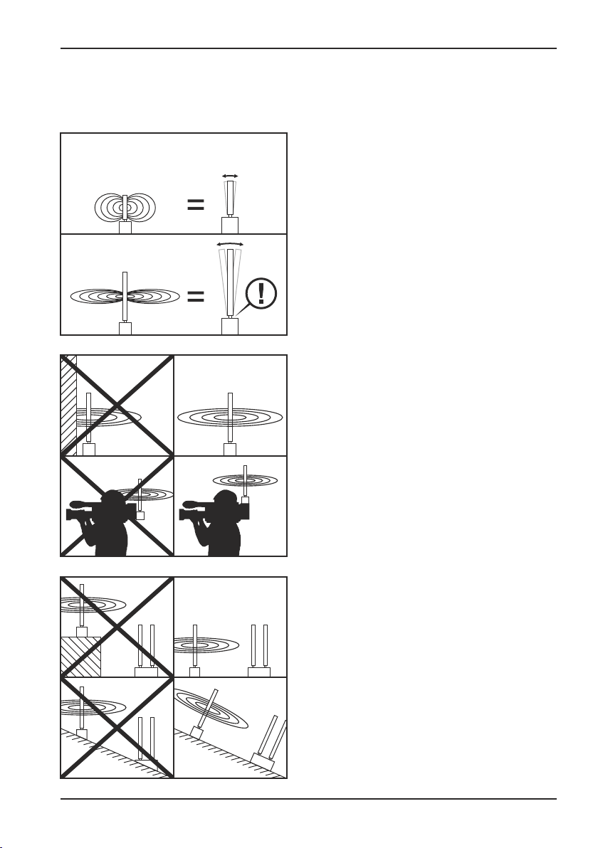
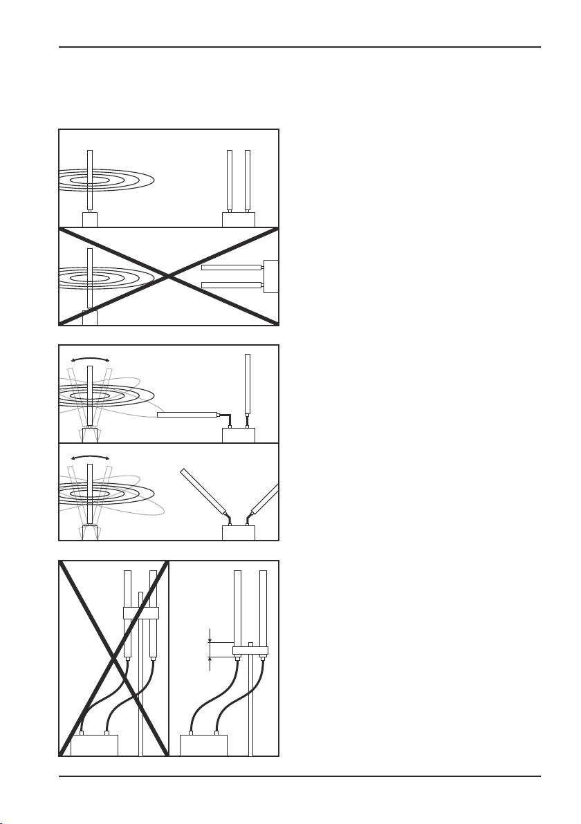
» Pay attention to the polarization of the
antennas.
Omnidirectional antennas normally are used
in vertical operation. Transmission and
reception antennas always have to be
aligned identically!
Exception:
fast-moving camera work, for example in
operations with steadycam etc.
Possible antenna configuration at the
receiver:
antenna 1 vertical (90°),
antenna 2 horizontal (0°)
or
antenna 1 turned to 45°
antenna 2 turned to 135°
A08 - 25.09.2015
max.
4cm
» Installation of antennas
(by grip, universal clamps etc.)
The grip is to be attached exclusively at the
lowest end of the antenna (maximum 4cm
from the lowest end), else the properties of
the antenna will be negatively affected.
8

VTQ WMS HD - V/G-Mount TX
Before operation
2. Before operation
2.3. Alignment and positioning of the antennas
» Are the antennas put at a distance from the system via cables ?
Please do pay attention to the length of the antenna cable. Just exclusively use the cable
"AirCell 7" (3m, TNC male / TNC female, Art.No.: 752010006), which is available as an accessory!
Please pay special attention to the quality of the cable and plugs used!
Example: DX-cable Aircell 7
Cable attenuation: . @2,4GHz: 0,36dB per metre
@5,8GHz: 0,65dB per metre
Effect on the range: at 3dB attenuation: range divided by 1,5
at 6dB attenuation: range divided by 2
at 12dB attenuation: range divided by 4
Calculation example: if you remote the antennas at a 5,8GHz-receiver with a 10m long
antenna cable from the system, the attenuation due to the cable will be 6,5dB.
If the range without antenna cable was 2000m, then the range will reduce to 1000m
because of the antenna cable (range 2000m divided by 2).
A08 - 25.09.2015
9
VTQ WMS HD - V/G-Mount TX
3. Connectors and control elements
Connectors and control elements
Antenna
(Reset)
SDI IN
SDI OUT
F
Fan
S
HD
VTQ WMS
Fan ON/OFF
V-Mount
VTQ WMS
V-Mount
Fan ON/OFF
Antenna
(Reset)
SDI IN
SDI OUT
F
Fan
S
HD
VTQ WMS
V-Mount
Rear viewFront view
HD
Antenna
(Reset)
SDI IN
SDI OUT
F
Fan
S
HD
VTQ WMS
Fan ON/OFF
G-Mount
VTQ WMS
G-Mount
Fan ON/OFF
Antenna
(Reset)
HD
VTQ WMS
G-Mount
Rear viewFront view
HD
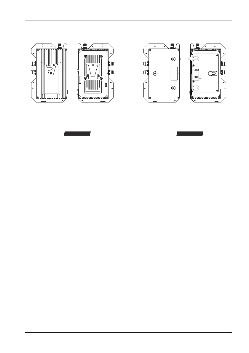
3.1. General notes
This digital video transmitter is mounted to the camera and power supplied via a conventional
V-Mount or G-Mount adapter.
The mounted transmitter is in-between the camera and battery. The construction enables the
power supply of camera and transmitter with only one battery.
SDI IN
SDI OUT
F
Fan
S
A08 - 25.09.2015
10

VTQ WMS HD - V/G-Mount TX
3. Connectors and control elements
3.2. Mounting the transmitter
1
For the mounting please proceed as
follows:
1. Remove the battery from your camera.
Loosen the interlock that fixes the battery.
Demount the battery from the camera.
2
2. Now fit the transmitter (as described in
the picture above) to the mount of your
camera and move it until it locks into place.
Connectors and control elements
A08 - 25.09.2015
3
3. Fit the battery to the connection on the
rear side of the transmitter and move it until
it locks into place.
4
4. The transmitter is now mounted to the
camera.
11
VTQ WMS HD - V/G-Mount TX
3. Connectors and control elements
Connectors and control elements
Antenna
(Reset)
SDI IN
Antenna
(Reset)
SDI IN
3
SDI OUT
F
Fan
S
VTQ WMS
V-Mount
HD
Fan ON/OFF
21
Fan ON/OFF
Rear viewFront view Side view
VTQ WMS
HD
V-Mount
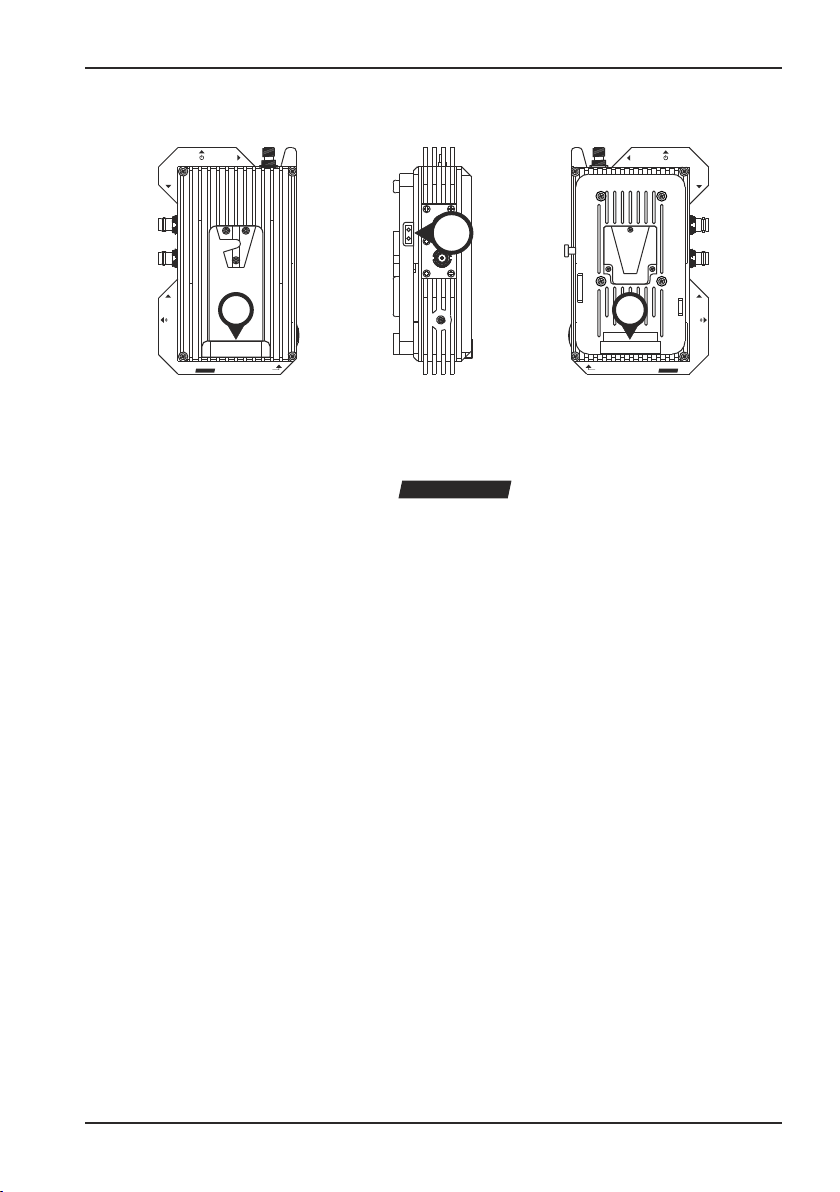
3.3. Power supply
After a successful mounting both camera and video transmitter are power supplied by the battery.
1. V-MOUNT (camera)
Here the transmitter is connected to the V-Mount of the camera. The camera is automatically
power supplied by the battery on the back of the transmitter.
VTQ WMS
V-Mount
SDI OUT
F
Fan
S
HD
2. V-MOUNT (battery)
An external V-Mount-battery is here connected to the transmitter. It power supplies the transmitter.
3. POWER-TAP
The transmitter is additionally equipped with a 2-pole power-tap-connection on the side. Thus a
camera head light may be directly power supplied by the V-Mount. The voltage output conforms
to the output of the connected battery.
A08 - 25.09.2015
12
VTQ WMS HD - V/G-Mount TX
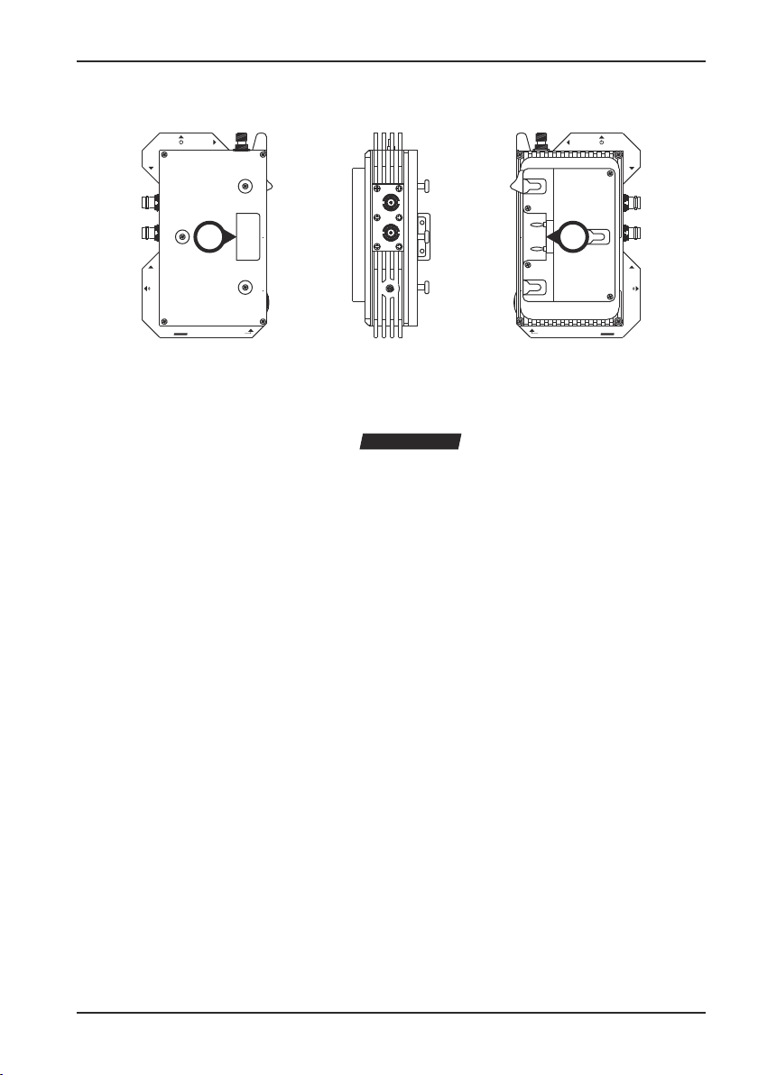
3. Connectors and control elements
Connectors and control elements
Antenna
(Reset)
SDI IN
Antenna
(Reset)
SDI IN
21
SDI OUT
F
Fan
S
HD
VTQ WMS
Fan ON/OFF
G-Mount
Fan ON/OFF
Rear viewFront view Side view
VTQ WMS
HD
G-Mount
3.3. Power supply
After a successful mounting both camera and video transmitter are power supplied by the battery.
1. G-MOUNT (camera)
Here the transmitter is connected to the G-Mount of the camera. The camera is automatically
power supplied by the transmitter.
VTQ WMS
SDI OUT
F
Fan
S
HD
G-Mount
2. G-MOUNT (battery)
Here an external G-Mount-battery is to be connected to the transmitter. It supplies the transmitter
with power.
A08 - 25.09.2015
13
 Loading...