

VTQ Videotronik WMS HD V-Mount HPQ, WMS HD G-Mount HPQ, WMS HD Free-Mount HG, WMS HD V-Mount HG, WMS HD Free-Mount HPQ Reference Manual
...
VTQ WMS HD - V/G-Mount TX
Wireless Monitoring Solution
VTQ WMS
V-Mount
G-Mount
HD
A08 - 25.09.2015
Reference guide

VTQ WMS HD - V/G-Mount TX
Table of content
Table of contents
1 Introduction ......................................................................................................................... 1
1.1 Safety instructions .............................................................................................................. 2
1.2 Contact information ............................................................................................................ 4
2 Before operation
2.1 Short description ................................................................................................................ 5
2.2 Assessment of the production environment ...................................................................... 6
2.3 Alignment and positioning of the antennas ....................................................................... 7
3 Connectors and control elements
3.1 General notes ................................................................................................................... 10
3.2 Mounting the transmitter ................................................................................................... 11
3.3 Power supply .................................................................................................................... 12
3.4 Connectors ....................................................................................................................... 14
4 Configuration
4.1 Starting the transmitter ..................................................................................................... 17
4.2 Screen saver ..................................................................................................................... 17
4.3 Program selection ............................................................................................................. 18
4.4 Modulation and transmission power ................................................................................ 19
4.5 Audio ................................................................................................................................. 21
4.6 Excess temperature .......................................................................................................... 22
4.7 Info menu .......................................................................................................................... 23
Factory reset ..................................................................................................................... 24
5 Putting into operation
5.1 Simple application errors .................................................................................................. 25
5.2 Basic check-up of the transmitter/receiver ....................................................................... 25
5.3 Channel evaluation ........................................................................................................... 26
6 Troubleshooting ................................................................................................................ 27
A1 Glossary ............................................................................................................................ 32
A2 Regulations for operation ................................................................................................. 36
Declaration of conformity ................................................................................................. 38
A3 Technical details ................................................................................................................40
A08 - 25.09.2015

VTQ WMS HD - V/G-Mount TX
Introduction
1. Introduction
Preliminary remarks
The present document, "Reference guide VTQ WMS HD Transmitter - V-Mount/G-Mount”, is
intended to be used for the proper set-up and operation of the wireless transmitter unit.
Manufacturer
VTQ Videotronik GmbH,
Tel: + 49 34771 510, Fax: + 49 34771 22044
E-Mail: products@vtq.de, Internet: http://www.vtq.de
Delivery including
1x VTQ
WMS HD Video Transmitter V-Mount / G-Mount
1x Antenna 0dB (SMA)
1x Adapter TNC/SMA
1x Reference guide
Optional accessories
Antenna (2.0 … 2.7GHz; 3 dBi; TNC male) Art.-No.: 7529 010003
Antenna (2.0 … 2.7GHz; 3 dBi; flex; TNC male) Art.-No.: 7529 010004
Antenna (2.2 … 2.5GHz; 6 dBi; starr; TNC male) Art.-No.: 7529 010005
Antenna (5.7 … 5.9GHz; 3 dBi; TNC male) Art.-No.: 7529 010007
Antenna (5.7 … 5.9GHz; 3 dBi; flex; TNC male) Art.-No.: 7529 010008
Antenna (5.7 … 5.9GHz; 5 dBi; starr; TNC male) Art.-No.: 7529 010009
DX-cable AIRCELL7 (3m, TNC male / TNC male) Art.-No.: 7529 010006
DX-Antenna 0dB with SMA 2.4GHz Art.-No.: 7502 000350
DX-Antenna 0dB with SMA 5.8GHz Art.-No.: 7558 000350
TNC corner adapter male-female 50Ohm Art.-No.: 7529 010010
Adapter TNC male to SMA female Art.-No.: 7529 010011
Gruene Strasse 2, 06268 Querfurt, Germany
About this reference guide
This Reference Guide provides instructions and information for the installation and operation of
the device. All essential steps from the connection up to the configuration are explained. Please
read this reference guide thoroughly in order to both avoid wrong operation and be able to use
the hardware in an optimal way. Please keep the manual in a safe place for future references.
A08 - 25.09.2015
1

VTQ WMS HD - V/G-Mount TX
Safety instructions
1.1. Safety instructions
Heed warnings!
All warnings on the product and in the operating instructions should be adhered to. The
manufacturer can not be held responsible for injuries or damage where warnings and cautions
have been ignored or taken lightly.
Read instructions!
All the safety and operating instructions should be read before this product is operated.
Follow instructions!
All operating and use instructions should be followed.
Retain instructions!
The safety and operating instructions should be retained for future reference.
Warning
Warnings give information which, if strictly observed, will prevent personal injury or death,
or damage to personal property or the environment. They are boxed and shaded for
emphasis, as in this example, and are placed immediately preceding the point at which the
reader requires them.
Cautions
Cautions give information which, if strictly followed, will prevent damage to equipment or
other goods. They are boxed for emphasis, as in this example, and are placed immediately
preceding the point at which the reader requires them.
Notes
Notes provide supplementary information. They are highlighted for emphasis, as in this
example, and are placed immediately after the relevant text.
A08 - 25.09.2015
2

VTQ WMS HD - V/G-Mount TX
Safety instructions
1.1. Safety instructions
Please always pay attention to the following warning instructions:
Just install the system in accordance with this reference guide.
Please exclusively use accessories authorized by the manufacturer.
Keep the system away from:
- places with high humidity
- places exposed to direct sunlight
- places with high temperatures
- places near open fire
Do not place the system near easily flammable substances like alcohol or thinners. In the event
that the internal electrical parts come into contact with easily flammable substances, there is a
danger of a fire outbreak or an electric shock.
Please prevent the system from rain or moisture in order to avoid the risk of a an electric shock.
In case liquids or similar substances end up inside the unit, please immediately disconnect the
voltage supply and contact the manufacturer.
Do not open, disassemble or modify the system. Incorrect handling may result in fire or electric
shock.
Do not connect the hardware with power supply units or voltage sources with a different voltage
than required or specified. The wrong voltage may result in fire or electric shock.
In case of thunder storms or when the system is not being used for a longer period of time,
please - as a precaution - disconnect the plug from socket.
Allow only the authorized manufacturer to carry out maintenance. The system has to be serviced,
if it has been damaged in any way (for example when liquids or items got into the system, when
the system was exposed to rain or moisture, when it does not work duly or was dropped and hit
the ground).
A08 - 25.09.2015
3

VTQ WMS HD - V/G-Mount TX
Contact informations
1.2. Contact information
Support Services
Our primary objective is to provide first class customer care that is tailored to your specific
business and operational needs. All levels are supported by one or more service performance
reviews to ensure the perfect partnership between VTQ and your business.
Return of equipment
If you need to return equipment for repair, please contact your distributor or the manufacturer:
VTQ Videotronik GmbH
Gruene Strasse 2
06268 Querfurt
Germany
Tel: +49 34771 510
Fax: +49 34771 22044
E-Mail: products@vtq.de
Internet: http://www.vtq.de
Technical publications
If you need to contact VTQ regarding this publication please e-mail to:
products@vtq.de.
A08 - 25.09.2015
4

VTQ WMS HD - V/G-Mount TX
Before operation
2. Before operation
2.1. Short description
The system operates according to the COFDM transmission mode, which is marked multiple
carrier operation and is particulary suitable for transmission of digital video- and audio signals.
Main features
» rugged housing and stable connectors
» different setups for high picture quality (HPQ) and extreme transmission ranges (HG)
» H.264 compression according to EBU standards
» small bandwidths (8MHz) for easier licensing outside of the ISM-bands
COFDM parameters
» Version .............................................. HG
......................................... (High Gain)
» Constellation .................................... QPSK
» Viterbi-FEC .......................................... 3/4
» Guard interval ..................................... 1/16
» Band width ....................................... 8MHz
» Version ........................................... HPQ
......................... (High Picture Quality)
» Constellation ..................... QPSK, 16QAM
» Viterbi-FEC .......................................... 3/4
» Guard interval ..................................... 1/16
» Band width ....................................... 8MHz
A08 - 25.09.2015
5

VTQ WMS HD - V/G-Mount TX
Before operation
2. Before operation
2.2. Assessment of the production environment
The exact observation and assessment of the production environment is the basic requirement to
ensure an ideal transmission.
AbsorptionAbsorption
wire-netting fence,
wire-netting fence,
trees, bushes,
trees, bushes,
leaves, etc.
leaves, etc.
ReflectionsReflectionsAttenuationAttenuation
high attenuation
high attenuation
barely reflections
barely reflections
limited penetration
limited penetration
good reflections
good reflections
» Which buildings and structures are located
in the surrounding area?
Radio signals are electromagnetic waves.
When these waves encounter an obstacle,
they will be reflected, attenuated or even
completely absorbed due to their physical
properties.
In general: The lower the frequency, the
better the penetration. The higher the
frequency, the worse the penetration.
» Which negative consequences result from
this?
Especially objects or structures made of
steel or metal can stop radio waves. This
also includes fences made of wire, steel
reinforcement in the masonry or metal
coated window panes.
Leaves from trees or bushes or rain or snow
as well lead to the attenuation or absorption
of the signal.
» Which positive effects does the
surrounding have for the transmission?
Smooth surfaces of buildings made of
masonry or reinforced concrete can be
used as reflection surfaces, in favor of the
transmission quality and range.
Buildings, walls,
Buildings, walls,
even surfaces
even surfaces
from ferroconcrete
from ferroconcrete
A08 - 25.09.2015
6
VTQ WMS HD - V/G-Mount TX
2. Before operation
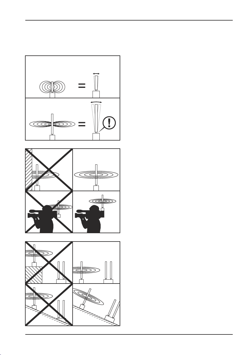
2.3. Alignment and positioning of the antennas
Before operation
4dB Antenna
6dB Antenna
» Selection of appropriate antennas
Pay attention to the correct frequency
range! Short antennas are optimal for
mobile applications, but normally are less
sensitive. Long antennas are more sensitive,
but are not appropriate for mobile
applications, as the antenna socket is
exposed to a greater leverage when under
intense pressure and can be damaged as a
result of this.
» Take care that the antennas are (as much
as possible) unobstructed !
Avoid every limitation of the transmission
and reception area by buildings or walls
directly at or in immediate surrounding of
the antenna.
Please make sure that, especially in a
mobile production, the antennas are able to
transmit and receive in all directions freely.
A08 - 25.09.2015
» Pay attention - if possible - to the identical
altitude of transmission and reception
antennas.
7
VTQ WMS HD - V/G-Mount TX
2. Before operation
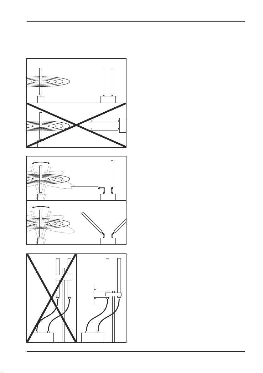
2.3. Alignment and positioning of the antennas
Before operation
» Pay attention to the polarization of the
antennas.
Omnidirectional antennas normally are used
in vertical operation. Transmission and
reception antennas always have to be
aligned identically!
Exception:
fast-moving camera work, for example in
operations with steadycam etc.
Possible antenna configuration at the
receiver:
antenna 1 vertical (90°),
antenna 2 horizontal (0°)
or
antenna 1 turned to 45°
antenna 2 turned to 135°
A08 - 25.09.2015
max.
4cm
» Installation of antennas
(by grip, universal clamps etc.)
The grip is to be attached exclusively at the
lowest end of the antenna (maximum 4cm
from the lowest end), else the properties of
the antenna will be negatively affected.
8

VTQ WMS HD - V/G-Mount TX
Before operation
2. Before operation
2.3. Alignment and positioning of the antennas
» Are the antennas put at a distance from the system via cables ?
Please do pay attention to the length of the antenna cable. Just exclusively use the cable
"AirCell 7" (3m, TNC male / TNC female, Art.No.: 752010006), which is available as an accessory!
Please pay special attention to the quality of the cable and plugs used!
Example: DX-cable Aircell 7
Cable attenuation: . @2,4GHz: 0,36dB per metre
@5,8GHz: 0,65dB per metre
Effect on the range: at 3dB attenuation: range divided by 1,5
at 6dB attenuation: range divided by 2
at 12dB attenuation: range divided by 4
Calculation example: if you remote the antennas at a 5,8GHz-receiver with a 10m long
antenna cable from the system, the attenuation due to the cable will be 6,5dB.
If the range without antenna cable was 2000m, then the range will reduce to 1000m
because of the antenna cable (range 2000m divided by 2).
A08 - 25.09.2015
9
VTQ WMS HD - V/G-Mount TX
3. Connectors and control elements
Connectors and control elements
Antenna
(Reset)
SDI IN
SDI OUT
F
Fan
S
HD
VTQ WMS
Fan ON/OFF
V-Mount
VTQ WMS
V-Mount
Fan ON/OFF
Antenna
(Reset)
SDI IN
SDI OUT
F
Fan
S
HD
VTQ WMS
V-Mount
Rear viewFront view
HD
Antenna
(Reset)
SDI IN
SDI OUT
F
Fan
S
HD
VTQ WMS
Fan ON/OFF
G-Mount
VTQ WMS
G-Mount
Fan ON/OFF
Antenna
(Reset)
HD
VTQ WMS
G-Mount
Rear viewFront view
HD
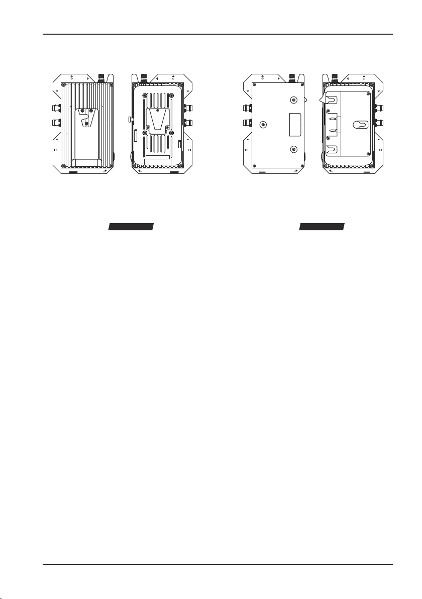
3.1. General notes
This digital video transmitter is mounted to the camera and power supplied via a conventional
V-Mount or G-Mount adapter.
The mounted transmitter is in-between the camera and battery. The construction enables the
power supply of camera and transmitter with only one battery.
SDI IN
SDI OUT
F
Fan
S
A08 - 25.09.2015
10

VTQ WMS HD - V/G-Mount TX
3. Connectors and control elements
3.2. Mounting the transmitter
1
For the mounting please proceed as
follows:
1. Remove the battery from your camera.
Loosen the interlock that fixes the battery.
Demount the battery from the camera.
2
2. Now fit the transmitter (as described in
the picture above) to the mount of your
camera and move it until it locks into place.
Connectors and control elements
A08 - 25.09.2015
3
3. Fit the battery to the connection on the
rear side of the transmitter and move it until
it locks into place.
4
4. The transmitter is now mounted to the
camera.
11
VTQ WMS HD - V/G-Mount TX
3. Connectors and control elements
Connectors and control elements
Antenna
(Reset)
SDI IN
Antenna
(Reset)
SDI IN
3
SDI OUT
F
Fan
S
VTQ WMS
V-Mount
HD
Fan ON/OFF
21
Fan ON/OFF
Rear viewFront view Side view
VTQ WMS
HD
V-Mount
3.3. Power supply
After a successful mounting both camera and video transmitter are power supplied by the battery.
1. V-MOUNT (camera)
Here the transmitter is connected to the V-Mount of the camera. The camera is automatically
power supplied by the battery on the back of the transmitter.
VTQ WMS
V-Mount
SDI OUT
F
Fan
S
HD
2. V-MOUNT (battery)
An external V-Mount-battery is here connected to the transmitter. It power supplies the transmitter.
3. POWER-TAP
The transmitter is additionally equipped with a 2-pole power-tap-connection on the side. Thus a
camera head light may be directly power supplied by the V-Mount. The voltage output conforms
to the output of the connected battery.
A08 - 25.09.2015
12
VTQ WMS HD - V/G-Mount TX
3. Connectors and control elements
Connectors and control elements
Antenna
(Reset)
SDI IN
Antenna
(Reset)
SDI IN
21
SDI OUT
F
Fan
S
HD
VTQ WMS
Fan ON/OFF
G-Mount
Fan ON/OFF
Rear viewFront view Side view
VTQ WMS
HD
G-Mount
3.3. Power supply
After a successful mounting both camera and video transmitter are power supplied by the battery.
1. G-MOUNT (camera)
Here the transmitter is connected to the G-Mount of the camera. The camera is automatically
power supplied by the transmitter.
VTQ WMS
SDI OUT
F
Fan
S
HD
G-Mount
2. G-MOUNT (battery)
Here an external G-Mount-battery is to be connected to the transmitter. It supplies the transmitter
with power.
A08 - 25.09.2015
13

VTQ WMS HD - V/G-Mount TX
Connectors and control elements
3. Connectors and control elements
1 2
3.4. Connectors
Please connect all peripherical hardware (antennas and cables) before switching on
the transmitter.
1. Power / Reset
Power switch: Turn the device on or off by pressing this switch.
2. Antenna
This TNC-port provides a connection for the antenna. We recommend to operate the system with
the antennas manufactured by VTQ Videotronik GmbH. (please see page 1 „Accessories“)
Connector: TNC female, 50 ohms
Please mind the frequency of the antenna, it has to match the frequency range of the
transmitter.
Do use the transmitter with attached antenna only! Never switch on the transmitter without
connecting an antenna first, else you run the risk of causing damage to the electronics.
In case you intend to operate your system according to R&TTE directive and thus without
the need to get an approval of your local/national authorities, please take into account
that, the transmission power (EIRP) may not exceed the maximum threshold value
defined by your local/national authorities!
A08 - 25.09.2015
14

VTQ WMS HD - V/G-Mount TX
Connectors and control elements
3. Connectors and control elements
345
3.4. Connectors
3. SDI IN
Via a BNC connector an SDI video signal (HD/SD-SDI) is fed to to the transmitter, which is then
wirelessly transmitted to the appropiate digital video receivers.
Connector: BNC, female, 75 ohms
Standard: ANSI / SMPTE 292M, SMPTE 259M
SDI signal level: 800mV (p-p) nominal ±10%
If the transmitter does not auto-detect a new video format after this has been changed,
please restart the transmitter.
If a video signal contains a lot of noise this produces huge data rates in the encoder. In
cases of extreme noise levels in the original video signal, the resulting data rate can
increase to such an amount that the remaining available data is insufficient to guarantee
a technically proper transmission of the image.
4. SDI OUT
The SDI signal (HD/SD-SDI, embedded Audio), which has been fed in via the video input, is
displayed here.
Connector: BNC, female, 75 Ohm
Standard: ANSI / SMPTE 292M, SMPTE 259M
SDI signal level: 800mV (p-p) nominal ±10%
5. Fan F/S
This dip-switch defines the speed of the internal fan.
S --> Slow
F --> Fast
A08 - 25.09.2015
15

VTQ WMS HD - V/G-Mount TX
3. Connectors and control elements
Connectors and control elements
7
3.4. Connectors
6. Fan ON/OFF
With this button you may turn off the internal fan. A red LED within the button indicates that the
fan is switched OFF.
Please do not cover the ventilation slot during operation.
The transmitter heats up faster when the fan is switched off. Please take care of a sufficient
circulation of air to avoid overheating of transmitter. We recommend to switch of the fan
in case of need for a short time only!
7. Control panel and display
The transmitter comes with an control panel consisting of display and a membrane keyboard with
3 keys. These 3 keys serve to conveniently navigate through the menu and ensures easy
operation. In the operating instructions the 3 keys are termed as follows:
6
A08 - 25.09.2015
Arrow up
Arrow downOK
16

VTQ WMS HD - V/G-Mount TX
4. Configuration
Configuration
HG
middle
4.1. Starting the transmitter
When the transmitter is switched on it starts with an initialisation which automatically identifies the
video norm of the input signal. The whole process takes no longer than 6 seconds.
As soon as the initialisation is finished the display should look like the above picture.
After the start-up it takes a total of approximately 30 seconds until a solid connection between
transmitter and receiver has been established. During this start-up process, occasional picture
flickering or frame drops are possible.
If the transmitter does not auto-detect a new video format after this has been changed,
please restart the transmitter.
After switching off the transmitter, the last selected program will be saved and is displayed at the
next start.
4.2. The screen saver
To save the display while operating the screen saver will be activated 30 seconds after the last
key operation. While the screen saver is activated the displayed items rolls across the screen.
audio
n
o
The screen saver can be stopped by pressing of any key.
A08 - 25.09.2015
17

VTQ WMS HD - V/G-Mount TX
Configuration
4. Configuration
HG
middle
4.3. Program selection
Each program channel has an assigned frequency. Depending on device up to 16 programme
channels are available.
Press the „Arrow Up“ button in order to change the programme channel. Press the button until
the desired programme channel is being displayed. 3 seconds after you have chosen your
channel, the modification in this setting is saved automatically.
Note: If you change the transmitter program you have to adjust the receiver to the same
program channel!
Program
1
2
3
4
5
6
7
8
9
10
11
12
13
14
15
16
17
18
19
20
1.4GHz
1210,0
1230,0
1250,0
1270,0
1290,0
1310,0
1330,0
1350,0
1370,0
1390,0
1410,0
1430,0
1450,0
1470,0
1490,0
1510,0
1530,0
1550,0
1570,0
1590,0
audio
n
o
2.4GHz
2205,0
2220,0
2240,0
2260,0
2280,0
2300,0
2320,0
2340,0
2360,0
2380,0
2400,0
2420,0
2440,0
2460,0
2480,0
2495,0
1
2.4GHz ISM
@10mW
5.8GHz
5730,0
5740,0
5750,0
5760,0
5770,0
5780,0
5790,0
5800,0
5810,0
5820,0
5830,0
5840,0
5850,0
5860,0
5870,0
5.8GHz ISM
@25mW
A08 - 25.09.2015
18

VTQ WMS HD - V/G-Mount TX
Configuration
4. Configuration
2
HG middle
4.4. Modulation and transmission power
Modulation and transmission power play an important role in the transmission.
Modulation
Choose „HG“ (High Gain) for a robust, almost faultless transmission. It is especially suitable for
mobile applications without line-of-sight-connection between transmitter and receiver. This setting
makes use of the QPSK modulation, thereby considerably reducing transmission interferences
and errors. In return, the image quality is lower than HPQ.
If you select „HPQ“ (High Picture Quality) you operate with better picture quality. This settings
uses the 16QAM modulation, which transfers a higher data rate per second, yet consequently is
more susceptible to transmission interferences and errors.
Please note that setting 16QAM is only available for HPQ models!
Transmission power
This function can switch transmission power to an admitted value. For example a 100mW
transmitter in frequency band 5.8GHz transmission power can be reduced to 25mW (“middle“)
so that the European regulations regarding licence free 5.8GHz-ISM-band are fulfilled.
In case you intend to operate your system according to R&TTE directive and thus without
the need to get an approval of your local/national authorities, please take into account
that, the transmission power (EIRP) may not exceed the maximum threshold value
defined by your local/national authorities!
A08 - 25.09.2015
19

VTQ WMS HD - V/G-Mount TX
Configuration
4. Configuration
2
HG middle
4.4. Modulation and transmission power
In order to change the modulation and the transmission power, press the "OK" button. Please
press the button until your desired setting appears on the display. 3 seconds after you have
chosen your setting, this modification is saved automatically.
The following settings are available, depending on the status of your model: HG or HPQ.
HG low
HG low
HPQ low
» Modulation: QPSK
» Transmission power: 10mW
HPQ low
» Modulation: 16QAM
» Transmission power: 10mW
HPQ middle
HG middle
HG high
HPQ high
A08 - 25.09.2015
HPQ medium
» Modulation: 16QAM
» Transmission power: 25mW
HG medium
» Modulation: QPSK
» Transmission power: 25mW
HG high
» Modulation: QPSK
» Transmission power: 100mW
HPQ high
» Modulation: 16QAM
» Transmission power: 100mW
20

VTQ WMS HD - V/G-Mount TX
Configuration
4. Configuration
3
audio off
4.5. Audio
The audio signal is embedded in the video signal (“Embedded Audio”).
The audio signal can be deactivated on request. As a result the saved data rate (~2MBit) leads to
an increase of image quality.
In order to change this setting press the
audio on
"Arrow down" button. With every keystroke the
setting "Audio on/Audio off" changes.
3 seconds after you have chosen your setting, this
modification is saved automatically.
audio off
A08 - 25.09.2015
21

VTQ WMS HD - V/G-Mount TX
Configuration
4. Configuration
HG
middle
4.6. Excess temperature
Due to insufficient ventilation or too high ambient temperature the transmitter heats up during
operation. If the maximum temperature exceeds 60°C, a blinking symbol appears instead of the
audio display and shows the current temperature.
If the temperature inside the transmitter exceeds 75°C, the internal electronics switches off and
stops the video transmission. In order to be able to restart the transmitter and thus continue the
transmission, it is inevitable to allow the transmitter a cool down period.
> 60°C » Temperature warning
> 75°C » Switch off
To avoid transmitter switch-off please switch on the internal ventilations. Every passively
cooled transmitter without internal ventilation needs to have sufficient circulation of air.
Never cover the radiator of the transmitter as this suppresses with the heat exchange!
A08 - 25.09.2015
22

VTQ WMS HD - V/G-Mount TX
Configuration
4. Configuration
I
video signal
4.7. Info menu
The info menu displays informations about video bitrate, temperature, firmware and manufacturer.
Furthermore, your are able to perform a factory reset.
You access the info menu by pressing the "OK"
I
video signal
button for a longer time. When entering, the first
menu item "VIDEO BITRATE" is displayed.
I
video bitrate
II
temperature
II
manufacturer
II
firmware
I
factory reset
II
end selection
In order to navigate in the menu, use the "ARROW
UP" and "ARROW DOWN" button. Choose a menu
item and press the "OK" button in order to enter the
respective menu items.
Some menu offer the possibility to access further
items by pressing the arrow buttons.
Exit the menu by pressing the "OK" button.
After exiting a menu the menu item "END
SELECTION" is displayed. You may select a different
menu item by using the arrow buttons or exit the
menu entirely by pressing "OK".
A08 - 25.09.2015
23

VTQ WMS HD - V/G-Mount TX
Configuration
4. Configuration
I
factory reset
4.7. Info menu
Factory reset
The factory reset will restore the factory default setting of the transmitter.
Navigate to the item "FACTORY RESET" and press the "OK" button. The message "CONFIRM!"
appears in the display.
You are still able to cancel this operation by pressing either the "ARROW UP" or
"ARROW DOWN" button. The message "BACK" appears in the display. Press the "OK"
button to cancel this operation.
Please press the "OK" button to reset the transmitter. The message "DO NOT TURN OFF“ appears
in the display. The device will shut down and reboot.
Do not turn off the device during the factory reset ! Wait until the transmitter has restarted
and the main menu is being displayed !
A08 - 25.09.2015
24

VTQ WMS HD - V/G-Mount TX
Putting into operation
5. Putting into operation
This checklist is a guideline for the most common problems that occur in practice. It is a
convenient first approach to various issues that will help you save time when working or
troubleshooting.
1. Simple application errors
» The provided voltage is not in the necessary range between 9 and 40 Volts
Voltage below 9 Volt: System does not power up
Voltage higher than 43 Volt: possible damage to the device
» provided Ampage is not in the necessary range from 325mA (at 40 Volt) to 1,444A (at 9 Volt)
» The temperature of the devices is raised by either an application error (e.g. transmitter is
covered with cloth, fabrics, etc.) or infavorable conditions (like permanent exposure to hot
sunlight), thus having a negative impact on the device's performance.
2. Basic check-up of the transmitter/receiver
In order to check the basic functions of the wireless device, please take the following points into
account:
This test should only be made in LOS conditions, the transmitter and receiver must be
placed in visibility range to each other. There must not be any obstacles, barriers, etc. in
between the two devices. Plus, both devices should not be moved during the test.
» Take care that transmitter and receiver are connected correctly.
» Adjust the transmission setting to any "low" profile (HG low or HPQ low)
» Choose an identical channel in both transmitter and receiver.
» The distance between transmitter and receiver should be 5 meter in LOS condition.
There must not be any obstacles between transmitter and receiver !
» The following information should now appear in the display of the receiver for both tuner.
Quality = 100
BER 0.00e-8
» If those values are displayed:
Increase the distance to 30 meters. If the values BER and quality remain constant, both
transmitter and receiver are basically working.
» If the quality level in 5 meter LOS condition is not at 100:
First check the antennas on the transmitter and receiver. If they are connected correctly,
change the channel on the transmitter and the receiver.
A08 - 25.09.2015
25

VTQ WMS HD - V/G-Mount TX
Putting into operation
5. Putting into operation
This checklist is a guideline for the most common problems that occur in practice. It is a
convenient first approach to various issues that will help you save time when working or
troubleshooting.
3. Channel evaluation
In order to check individual channels regarding interferences by other wieless sources, please do
the following:
» Take care that transmitter and receiver are connected correctly.
» Adjust the transmission setting to any "low" profile (HG low or HPQ low)
» Choose an identical channel in both transmitter and receiver.
» The distance between transmitter and receiver (in LOS condition) should be adjusted until
the receiver displays the following values:
Level (RF): 35-40
Quality (SNR) : 100
BER: 0.00e-8
» If the values for both quality (SNR) and BER remain solid (SNR between 95-100 and BER
between e-8 and e-7) under these conditions, the channel is devoid of interferences.
A08 - 25.09.2015
26

VTQ WMS HD - V/G-Mount TX
Troubleshooting
6. Troubleshooting
This checklist is a guideline for the most common problems that occur in practice. It is a
convenient first approach to various issues that will help you save time when working or
troubleshooting.
1. Transmitter / receiver without function (display off)
A. Check power source
--> Power source (battery/camera/mains adapter)
--> Cable (broken?)
--> Contacts (pins, connector)
B. ON/OFF switch (only V-Mount TX, Handheld RX and V-Mount RX)
2. No video signal
A. Check signal feeding at the transmitter
--> Signal source (camera/player)
--> Configuration of video output (no CVBS, SD/HD-SDI only)
--> Cable (according the specifications)
--> Contacts (pins, connector)
B. Check wiring
--> SDI OUT (source) --> SDI IN (transmitter)
--> SDI OUT (receiver) --> SDI IN (monitor)
Connect the SDI Output of the receiver directly to a monitor without further peripheral
equipment in-between, in order to avoid further possible error sources.
(signal converter or distributor)
Ideally you are able to compare both the clean video source with the receiver output signal
in order to come to a conclusion
C. Display of video format at transmitters display
--> Disconnect and re-connect the BNC connector at the transmitter
--> automatic detection of the video format
If the transmitter, despite an error-free check-up of the previous points, does not automatically
show a video format, the fed video signal might not be in accordance with the necessary
SD-SDI/HD-SDI specification (SD-SDI: SMPTE 259M; HD-SDI: SMPTE 292M)
-> if possible cross-check with a standardized signal
D. Check settings and parameters
--> Identical channels at transmitter and receiver
--> in case of multiple pairs of TX/RX: distinct choice of channels
--> Display: Tuner not locked ?
--> transmission system operates in line of sight (5m line-of-sight LOS)?
--> correct antenna (frequency range) in use?
--> Antenna(cable) properly connected?
Should these 3 previous points be correct, please contact the corresponding service
for your area.
A08 - 25.09.2015
27

VTQ WMS HD - V/G-Mount TX
6. Troubleshooting
2. No video signal
--> Explicit peak at receivers OLED display for level & quality
No? --> Check BER: perfect if constant at 0.00 e-8
If BER > 0.00e-8 (z.B. e-7, e-6, etc.):
--> transmission systems works in line of sight (LOS)?
--> correct antenna (frequency range) in use?
--> Antenna(cable) properly connected?
If these 3 points are correct:
--> Change channel (more than one transmitter operates at the frequency?)
Should the problem prevail:
--> Test of identical transmitter with identical parameters
Should the problem prevail:
--> Contact service
3. Transmission range / Stability too low
(Please first exclude all possible error sources mentioned in point 6.1.)
A. Distance between TX and RX too large?
--> TX & RX in proper distance (LOS)?
B. Are the antennas aligned identically?
--> Standard: vertical polarisation
C. Booth receiver tuners displays identical parameters for RF level?
No: --> are 2 identical antennas connected?
--> switch the antennas and connect them to the opposite connector
--> Check and - if necessary - exchange cables
If the error "sticks" to and moves with one antenna or cable, exchange the identified
error source
Yes: --> If quality and bit error rate are bad, then check:
--> Correct antennas (frequency range) in use?
--> Antennas properly connected?
--> Too low distance between transmitter & receiver
--> Minimum 1 meter distance between TX & RX (ideal distance: 10m)
--> Is the frequency occupied by another transmission system?
--> Change channel
Should the problem prevail:
--> Test of identical transmitter with identical parameters
Should the problem prevail:
--> Contact service
Troubleshooting
A08 - 25.09.2015
28

VTQ WMS HD - V/G-Mount TX
Remarks
Remarks
A08 - 25.09.2015
29

VTQ WMS HD - V/G-Mount TX
Remarks
Remarks
A08 - 25.09.2015
30

VTQ WMS HD - V/G-Mount TX
Remarks
Remarks
A08 - 25.09.2015
31

VTQ WMS HD - V/G-Mount TX
Glossary
A1. Glossary
» BAS
(„Bild-Austast-Synchron-Signal“ = Picture blanking synchronous signal)
Common name of the monochrome TV picture signal. It consists of the picture information and the blanking
signal.
» BER
(„Bit Error Rate“)
The bit error rate (BER) is the percentage of bits that have errors relative to the total number of bits received in a
transmission. The BER is an indication of how often a package of data has to be retransmitted because of an
error. Sometimes a slower data rate will improve the transmission quality because the BER might be reduced.
» Booster
In this manual it is the name of an amplifier that increases the transmission power to have a larger range.
» CBR
(„Constant Bit Rate“)
Constant Bit Rate is a kind of compression technology. Using constant bit rate means that the quality is altered
to reduce the information to fit the fixed bit rate. Overflowing the available bit rate can lead to lost bits, whereas
the target of this technology is to stay just under the available bit rate. The degree of success in almost filling
the available space is a measure of the quality and efficiency of the compression system.
» COFDM
(„Coded Orthogonal Frequency Division Multiplexing“)
Coded Orthogonal Frequency Division Multiplexing is a modulation scheme which is used by the DVB digital
television system. It allows the use of multiple carriers. Concatenated error correction is integrated. The guard
interval is selectable. That makes the system resistant against multipath fading and burst failures and therefore
the best choice for mobile receivers.
» DVB-T
(„Digital Video Broadcasting - Terrestrial“)
Digital Video Broadcasting – Terrestrial, a transmission scheme for terrestrial digital television. It uses Coded
Orthogonal Frequency Division Multiplexing (COFDM), which spreads the signals over a large number of
carriers to enable it to operate effectively in very strong multipath environments.
» EIRP
(„Effective Isotropic Radiated Power“)
Effective isotropically radiated power is the amount of power emitted by an isotropic antenna. EIRP takes into
account the losses e.g. of connectors and the gain of the antenna. The EIRP is often stated in terms of dBm,
mW or dBW.
A08 - 25.09.2015
32

VTQ WMS HD - V/G-Mount TX
Glossary
A1. Glossary
» ETSI
(“European Telecommunications Standards Institute”)
The ETSI is a charitable institute founded to set Europewide standards regarding telecommunication. It was
founded in 1988 on the initiative of the European Committee. It has over 700 members of over 50 countries
inclusive operating companies, service providers, administrations, and producers.
» FBAS
(composite colour picture signal)
The FBAS signal identifys the entire TV signal that is required for the colour – image transmission. It consits of a
colour signal (F), image signal (B), blanking signal (A) and the synchronous signal (S). In English: CVBS
(Colour Video Blanking Signal).
» FEC
(“Forward-Error-Correction”)
This technology is used to reduce the error rate regarding digital data transmission. In the transmitter the
transmission data is coded by the Forward Error Correction so that the receiver is able to recognize and correct
the errors. It is used e.g. on compact discs (CD) or for wireless transmissions.
» Guard Interval (GI)
The guard interval is one of the most important parameters for robustness of the COFDM-signals. It is inserted
between two successive symbols and thereby avoids interference by echoes.
» GoP
(„Group of Picture“)
At this kind of compression pictures for different purposes are compressed at different levels The I-pictures are
compressed regardless of the other pictures. These are the biggest pictures. All other pictures are reduced in
size in regard of other pictures in the video stream. These different kinds of pictures are used in different
frequencies. Typically they appear as so-called GOP (Group of Pictures). One GOP reaches from one I-picture
to the next. Often they have a length of half a second.
» H.264
H.264 (MPEG-4 AVC) is a standard in videocompression. It performs with an approximately 3 times higher
coding efficiency than MPEG2 (h262). This means that with only a third of the data rate compared to MPEG2 a
similar picture quality is achieved. At the same time the computing effort increases by up to the factor 3.
A08 - 25.09.2015
33

VTQ WMS HD - V/G-Mount TX
Glossary
A1. Glossary
» HF-Performance
(„High Frequency“)
In contrast to EIRP the HF-performance does not measure the radiation power but the pure transmission
performance of a transmitter measured at the antenna output jack.
» ISM
(“Industrial, Scientific, and Medical Band”)
ISM marks frequency bands which can be used for industry, science, and medicine purposes. It is possible to
use them free of licence fees and charges.
» MER
(„Modulation Error Ratio“)
The Modulatio Error Ratio is - according to the DVB standard - a parameter for the assessment of interferences
during the transmission. All perturbations are concentrated in one measured value. The higher the MER value,
the better the signal quality.
» MPEG
(„Moving Pictures Experts Group“)
The MPEG is a experts group which standardizes video compression. MPEG-2 is a MPEG Standard regarding
video and audio data compression. Also this standard is used by DVB-T, the digital television in Germany.
» NTSC
(“National Television Systems Committee”)
NTSC is a system of the analogue colour television in the United States and in parts of Eastern Asia. It is the
pedant to the European PAL Standard.
» OFDM
(“Orthogonal Frequency Division Multiplexing”)
Instead of modulating only a single carrier several thousand carriers are modulated at the same time. Every
single carrier is phase and amplitude modulated and therefore carries the information of several bits per symbol
(typically 2 or 6 bit).
» OSD
(“On Screen Display”)
On the screen a menu of the current picture is displayed. These menus serve for operation and set up of the
devise.
A08 - 25.09.2015
34

VTQ WMS HD - V/G-Mount TX
Glossary
A1. Glossary
» PAL
(“Phase Alternating Line”)
PAL marks an analogue colour television norm. PAL was developed by Walter Bruch in Germany who applied
for patent in 1963. Main objective of this norm was to reduce the colour line error. The principal concepts of
signal transmission were taken from the NTSC-system.
» QAM
(“Quadrature Amplitude Modulation”)
QAM is a coding method which combines the digital amplitude modulation and the digital phase modulation.
The objective is a constellation of signal points which represent a definite combination of bits.
» QPSK
(“Quadrature Phase Shift Keying”)
QPSK is a digital modulation method. With this method it is possible to transmit 2 bits per symbol. Thus the
exploitation of the available band width can be doubled.
» SDI
(“Serial Digital Interface”)
The SDI Standard describes the transmission of a digital serial video stream. The video data is transmitted
uncompressed with bit rates from 143 Mbit/s (NTSC composite) to 360 Mbit/s (16x9 4:2:2 component). The
digitalized audio data can be transmitted in the horizontal blanking interval. Also the HDTV transmission can be
standardized by SDI which is called HD-SDI. Here the data rate is 1,485 Gbit/s.
» SMA
Sub-Miniature Version A”)
SMA marks a high frequency plug connector for antennas. Appropriate antennas with this connection can be
connected to the system.
» VBR
(“Variable Bit Rate”)
With this compression method video and audio data are transmitted by a variable bit rate. The memory volume
of the therefore used material is compressed in regard of the signal complexity. Per time unit an appropriate
data amount is produced depending of the signal complexity. The opposite of this method is the constant bit
rate (CBR).
A08 - 25.09.2015
35

VTQ WMS HD - V/G-Mount TX
Regulations for operation
A2. Regulations for operation
Please consider the local or national regulations concerning the use of wireless equipment in
your country. The devices carry the CE sign.
» VTQ WMS HD
Frequency range 2.400 - 2.4835GHz
Transmission power max. 10mW (EIRP)
Frequency range 5.725 - 5.875GHz
Transmission power max. 25mW (EIRP)
These products operate according to the regulations of the R&TTE Directive and are class 1
equipment, that means, they can be used without any approval and licence-free in all member
states.
Please consider the local or regional regulation concerning the transmission power (EIRP)
when installing gain antennas!
» VTQ WMS HD (kein ISM)
Frequency range 1.200 - 1.600GHz
Frequency range 2.200 - 2.500GHz
Frequency range 2.400 - 2.4835GHz
Transmission power > 10mW (EIRP)
Frequency range 5.725 - 5.875GHz
Transmission power > 25mW (EIRP)
This range of products is not specified as “Class 1” equipment according to the R&TTE Directive
(1999/5/EC). You should contact the telecommunication authorities in your country to find out,
whether an operation is allowed or not, or if you must apply for a licence. Please check whether
the product must be notified before you launch it on the local market.
A08 - 25.09.2015
36

VTQ WMS HD - V/G-Mount TX
Regulations for operation
A2. Regulations for operation
For utilizations in Europe there is the possibilty of procuring a licence at the regulatory authority
for telecommunications of each country.
Before putting them to use in all other countries please inform yourself about the licensing
procedures of each country.
Germany
Bundesnetzagentur
Postfach 8001
53105 Bonn
Telefon 0228 / 14 0
Telefax 0228 / 14 88 72
E-Mail: info@bnetza.de
Webseite: www.bnetza.de
Swiss
Federal Office for Communications
Rue de L'avenir 44
CH-2501 Biel-Bienne
SWITZERLAND
E-Mail: info@bakom.admin.ch
Webseite: www.bakom.admin.ch
Austria
Austrian Regulatory Authority
for Broadcasting and Telecommunications
Mariahilferstraße 77-79
A-1060 Vienna
AUSTRIA
E-Mail: rtr@rtr.at
Webseite: www.rtr.at
A08 - 25.09.2015
37

VTQ WMS HD - V/G-Mount TX
Declaration of conformity
Dr. Steffen Enke
Managing Director
Conformity Transmitter Series „VTQ WMS HD“ A02 vom 01.09.2015
A08 - 25.09.2015
Jürgen Bergner
Test Engineer
38

VTQ WMS HD - V/G-Mount TX
Declaration of conformity
Dr. Steffen Enke
Managing Director
Conformity Receiver Series „VTQ WMS HD“ A02 vom 01.09.2015
A08 - 25.09.2015
Jürgen Bergner
Test Engineer
39

VTQ WMS HD - V/G-Mount TX
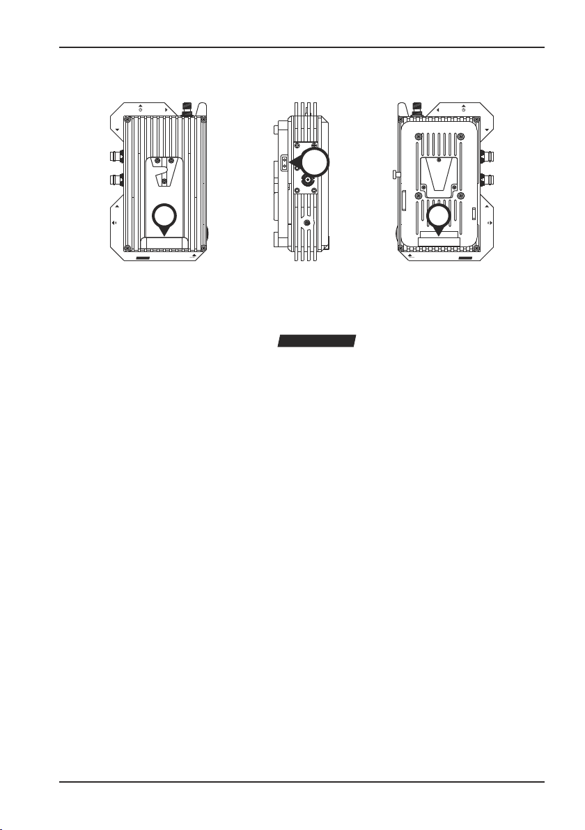
A3. Technical details
Technical details
176
151
VTQ WMS
V-Mount
62 110
48 92
SDI IN
SDI OUT
F
Fan
S
HD
(Reset)
Antenna
A08 - 25.09.2015
VTQ WMS
V-Mount
HD
Fan ON/OFF
40

VTQ WMS HD - V/G-Mount TX
A3. Technical details
62 110
48 92
Technical details
110
92
48
62
Antenna
(Reset)
SDI IN
176
A08 - 25.09.2015
151
Fan ON/OFF
VTQ WMS
V-Mount
SDI OUT
F
Fan
S
HD
41

VTQ WMS HD - V/G-Mount TX
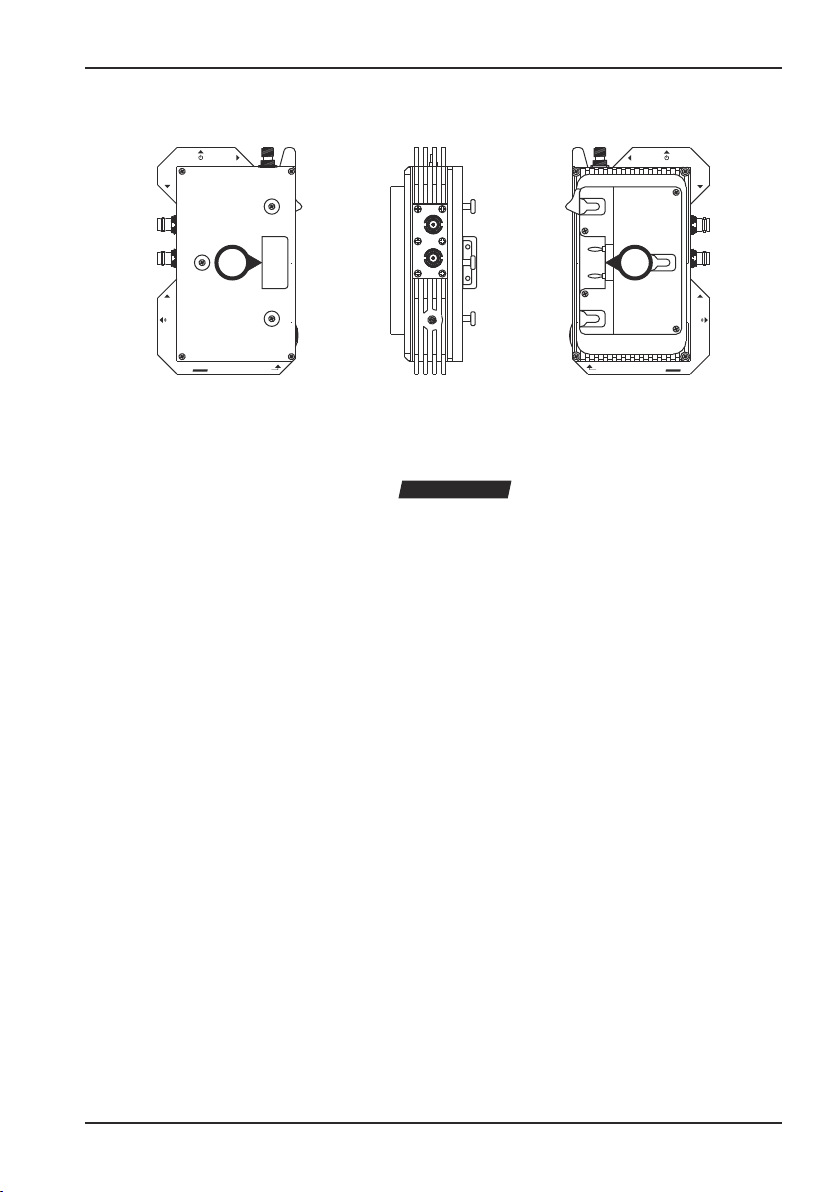
A3. Technical details
Technical details
176
151
VTQ WMS
G-Mount
65 115
48 92
(Reset)
SDI IN
SDI OUT
F
Fan
S
HD
Antenna
A08 - 25.09.2015
VTQ WMS
G-Mount
HD
Fan ON/OFF
42

VTQ WMS HD - V/G-Mount TX
A3. Technical details
65 115
48 92
Technical details
115
92
48
65
Antenna
(Reset)
SDI IN
176
A08 - 25.09.2015
151
Fan ON/OFF
VTQ WMS
G-Mount
SDI OUT
F
Fan
S
HD
43

VTQ WMS HD - V/G-Mount TX
A3. Technical details
HF VIDEO
Frequenzbereiche / Frequency range 1.200 - 1.600GHz
2.200 - 2.500GHz
5.725 - 5.875GHz
Sendeleistung // Transmission power 10 / 25 / 100mW (HF)
Frequenzraster // Frequency pattern 20MHz
Frequenzstabilität // Frequency stability ±2ppm
MODULATION
Modulation // Modulation HG: COFDM (QPSK)
HPQ: COFDM (QPSK, 16QAM)
Punktierung // Codec rate 3/4
Guardintervall // Guard interval 1/16
Symbollänge // Carriers 2k
Bandbreite // Bandwidth 8MHz
VIDEO ENCODER
Methode // Method H.264
Verzögerung // Delay 22ms (Enc/Dec)
Videonorm // Video standard PAL / NTSC
Videoeingang // Video input HD/SD SDI
Technical details
VIDEO ENCODER
HD-Format // HD format 1080i50, 1080i59,94, 1080i60
1080p23,98, 1080p24, 1080p25
1080p29,97, 1080p30
1080psf23,98, 1080psf24, 1080psf25
1080psf29,97, 1080psf30
720p23,98, 720p24, 720p25, 720p29,97
720p30, 720p50, 720p59,94, 720p60
SD-Format // SD format 576i50 (PAL)
480i59,94 (NTSC), 480i60 (NTSC)
A08 - 25.09.2015
44

VTQ WMS HD - V/G-Mount TX
A3. Technical details
AUDIO
Audio // Audio Embedded Audio (via SDI)
POWER
Spannungsversorgung // Power supply 9 - 40V DC
Leistungsaufnahme // Power consumption max. 12W
ENVIRONMENTAL
Temperatur Betrieb // Operating temperature -10°C - +50°C
Temperatur Lagerung // Storage temperature -10°C - +50°C
PHYSICAL CHARACTERISTICS
Abmessungen // Dimensions 110 x 176 x 62mm (V-Mount)
115 x 176 x 65mm (G-Mount)
Gewicht // Weight 1060g (V-Mount)
1060g (G-Mount)
CONNECTORS
SDI IN (HD/SD, Embedded Audio) BNC
SDI OUT (HD/SD, Embedded Audio) BNC
DC IN via V-Mount / G-Mount
Antenna TNC
Technical details
A08 - 25.09.2015
45

VTQ WMS HD - V/G-Mount TX
This product was produced under a Management System certified by ISO/TS 16949 and DIN EN
ISO 9001:2000.
If you have any problems when installing the device, please, do not hesitate to contact us.
We would be pleased to help you.
Notice: Any liability for misprints excluded. Technical details are subject to change without notice.
A08 - 25.09.2015
VTQ Videotronik GmbH
Grüne Straße 2 · 06268 Querfurt
Tel.: +49 34771 510 · Fax.: +49 34771 22044
Internet: www.vtq.de · E-Mail: main@vtq.de
 Loading...