

VTL TL6.5 Owner's Manual

VTL
TL6.5 Signature Line Stage Preamplifier
O w n e r ’ s M a n u a l

MAKING TUBES USER FRIENDLY
VTL TL6.5 Signature Line Preamplifier
Information in this document is subject to change without notice. No part of this document may be reproduced or
transmitted in any form or by any means, electronic or mechanical, for any purpose, without the express written
permission by VTL.
Version History:
Version 2.2 November, 2007
Part Number: OM-6.5
Copyright © 2008 by VTL Amplifiers Inc. All rights reserved.
4774 Murrieta Street, Suite 10
Chino, CA 91710, USA
Phone 909.627.5944 • Fax 909.627.6988
Email: mail@vtl.com • http://www.vtl.com/


Table of Contents
CHAPTER 1.........................................................................................................................................................................1
INTRODUCTION................................................................................................................................................................1
Symbol Conventions used in this guide ......................................................................................................................2
Electrical Safety Notice ..............................................................................................................................................3
Water and Moisture....................................................................................................................................................3
Location and Ventilation............................................................................................................................................3
Warning – To avoid risk of failure due to overheating, do not stack components...................3
Servicing .....................................................................................................................................................................4
Operational Warnings................................................................................................................................................4
CHAPTER 2.........................................................................................................................................................................6
GETTING STARTED..........................................................................................................................................................6
Unpacking the TL 6.5 from its box.............................................................................................................................6
Quick Start..................................................................................................................................................................6
TL 6.5 Front Panel Controls ......................................................................................................................................8
The Preamplifier’s Back Panel ............................................................................................................................... 11
Back Panel Connections and controls ............................................................................................................. 11
The Remote Control Hand-held Unit ...................................................................................................................... 12
Fitting the Batteries to the Remote Control..................................................................................................... 13
Voltage Setting......................................................................................................................................................... 14
Power Source for the VTL TL 6.5 Preamplifier...................................................................................................... 14
Connecting the Preamplifier to your system........................................................................................................... 15
Connecting to a Turntable ............................................................................................................................... 15
Select and Connect Source Components......................................................................................................... 15
Connecting a second pair of amplifiers .................................................................................................................. 16
Connecting the TL 6.5 to a Home Theater System.................................................................................................. 17
Using the TL 6.5 to trigger other devices................................................................................................................ 17
CHAPTER 3...................................................................................................................................................................... 19
OPERATING THE PREAMPLIFIER................................................................................................................................... 19
Powering your preamplifier and the rest of your system on................................................................................... 19
Ground Loop Hum................................................................................................................................................... 20
Using the Preamplifier with the Remote Control.................................................................................................... 21
Using the Tape Loop to monitor recordings........................................................................................................... 21
Operating Modes and Factory Default Settings ..................................................................................................... 22
Quick Reference: Special Programming Functions................................................................................................ 23
LED Indications....................................................................................................................................................... 24
Programming the Preamplifier’s function controls................................................................................................ 26
Using the preamplifier with RS232 control .................................................................................................... 36
Powering the system off........................................................................................................................................... 40
CHAPTER 4...................................................................................................................................................................... 41
CARE AND MAINTENANCE OF YOUR VTL PREAMPLIFIER........................................................................................... 41
Break In Period........................................................................................................................................................ 41
Tube Life .................................................................................................................................................................. 41
Changing Tubes....................................................................................................................................................... 41
TL6.5 Preamplifier Owner’s Manual
VTL
i

Changing the Main, Output stage and Power Supply Protection Fuses.................................................................43
Cleaning ...................................................................................................................................................................44
Troubleshooting ....................................................................................................................................................... 45
CHAPTER 5 ......................................................................................................................................................................48
TL-6.5 SPECIFICATIONS ...............................................................................................................................................48
CHAPTER 6 ......................................................................................................................................................................49
WARRANTY...................................................................................................................................................................49
APPENDIX........................................................................................................................................................................51
Warranty Registration..............................................................................................................................................51
Service Notes............................................................................................................................................................51
TL6.5 Preamplifier Owner’s Manual
VTL
ii

CHAPTER 1
Introduction
Congratulations on your purchase of a VTL Signature Preamplifier: “A new single-chassis preamplifier
design to challenge all others.”
his hand crafted component is designed to deliver superb performance for your
listening pleasure for many years to come. In order to get the most benefit from your
purchase, we recommend that you take sufficient time to get familiar with the features
T
of this product. Please take a moment to read through this owner’s manual, as it
contains all of the installation procedures needed to connect your new TL 6.5 to the rest of
your audio system, as well as the many functions that the TL 6.5 can perform. After you have
finished reading this manual it should be kept it in a safe place for future reference.
As a significant and important product for VTL, the TL6.5 Signature Line Preamplifier is a fully
differential circuit, and is designed to be the ideal matching front end for the VTL Reference
power amplifiers, as well as the Signature MB-185 and MB-450 monoblocks, but due to the
design of the TL 6.5 it will drive any power amplifier with the same result.
As VTL’s top preamplifier in the Signature family, with an integral power supply control section
and multiple fully regulated power supplies to preserve tonal and spatial accuracy, the TL 6.5
incorporates all of the design specification and features of the VTL Signature series, and
sonically leads the listener through the intricate tapestry of musical layers, with superior control
and tonal balance. The TL 6.5 Preamplifier truly represents a fresh breakthrough in furthering
the refinement of the VTL sound, and the ability of the new TL 6.5 to articulate and present
the listener with a broad, cohesive picture of the total musical soundscape in a dynamic, nimble,
full range sound gives it the distinction it bears as our Signature Preamplifier. As you will find,
this preamplifier commands your attention to music itself and unravels before your eyes and
ears the most intricate emotional layers that is the essence of music.
Preamplifiers offer the user many benefits that direct connections cannot. A line stage with gain
(and therefore dynamic headroom) always yields superior sound in dynamic musical passages.
Ease of installation is another primary benefit with preamplifiers. Yet another benefit from a
high current output buffer is to lower the output impedance to drive the next stage (usually a
power amplifier, with unknown input impedance) and/or the interconnecting cable, with
potentially high capacitance in long lengths.
The VTL TL 6.5 Signature Line preamplifier is both a fully active line level preamplifier and a
complete source control center in one package, and it offers complete predictability of
performance with little or no change of response in a wide range of systems and environments.
This preamplifier is a true Signature Component, insofar as it contains some of the most
advanced thinking in preamplifier design today.
The major design goal for the TL 6.5 was to sonically outperform any existing single-chassis
preamplifier design, using measurements to back up empirical findings, and the technical
challenge of designing a fully differential circuit with sufficient common mode rejection ratio
TL6.5 Preamplifier Owner’s Manual
VTL
1

using tubes is no small challenge. To achieve the design goals we had to address two
fundamental issues: (1) Deal with the sonic bottlenecks that occur in the multiple stages and
functions of known preamplifier designs, and (2) design a preamplifier that will work in as wide
a variety of conditions as possible, as unaffected by outside environmental influences as
possible. The sonic performance should be musical, predictable and consistent, regardless of
AC condition, load, source component, physical vibrations or digital or other external radiated
noise.
During the long four-plus years of the R&D development cycle of this project, the 5-man VTL
engineering team was given the mission to create the best single-chassis preamplifier that we
could possibly make. During this time our panel of listeners was given the mandate to be
relentless in pushing the requirements for the design envelope -- parts were changed and
modules re-designed over and over again until we were satisfied with all aspects of the sonic
and measured performance.
Making a preamplifier that is capable of driving any load with any length of cable without
flinching is an extremely challenging prospect. In designing a completely novel push-pull low
impedance output stage, and taking a radical approach to the volume potentiometer by
incorporating relays and discrete resistors in an innovative combination, we have finally been
able to significantly improve upon the highly-regarded TL5.5 sound. By coupling this
technology to multiple super-regulated power supplies we have dramatically improved on the
preamplifier’s capability to drive any power amplifier, with truly superior resolution, spatial
imaging and bass control.
Finally, the VTL TL 6.5 Preamplifier is designed primarily for the user whose primary source is
a line source. If phono is a primary source then a separate phono stage will be required to step
the cartridge voltage up to line level and to handle the RIAA equalization needed to re-equalize
the signal from the record. Since this stage is usually a high gain stage and is therefore
susceptible to noise, it is sonically better to separate this stage from the line preamplifier.
The VTL team is proud that you have selected our Signature preamplifier as a new member of
your home audio system. This preamplifier is designed to give you the convenience and
flexibility to manage all your audio and video sources, while at the same time giving you the
musical experience that is the most alive and the truest to your source, and we certainly wish
you many hours of enjoyment from it.
Symbol Conv entions used in this guide
Certain symbols are used in this owner’s manual to draw your attention to important
points being discussed. For your own safety and that of your equipment you should
note and heed the warnings that follow these symbols.
The “Warning - Pay particular Attention” symbol used is
And the “Warning – Observe These Precautions for Your Safety” is
TL6.5 Preamplifier Owner’s Manual
VTL
2
Electrical Safety Notice
Electrical voltage from power cables can be hazardous. We
recommend that the power cord used with this unit be
connected to a properly grounded AC outlet. There are
hazardous voltages present in the unit, and to prevent electrical
shock, do not remove the cover of this preamplifier, and under no circumstances while the
unit is powered on.
Warning – Under no circumstances should any
attempt be made to circumvent the ground
system to the AC line for any reason
lifted system can be potentially extremely dangerous, both to
persons that might come in contact with the unit, and to the unit
itself, and proper RF shielding cannot be attained without a secure ground connection.
Damage to the unit that is the result of improper AC connection and grounding will not be
covered under the warranty.
. Using a ground
Prior to connecting this preamplifier to any audio or video equipment
in your system, make sure this unit’s power (and the rest of the
equipment connected to its input and output channels) is turned off.
Adding or removing input or output cables to the preamplifier while
the system is powered on can cause damage to the preamplifier and possibly also to the
rest of the system.
Water and Moisture
The TL 6.5 should be kept away from sources of water or
moisture. If liquid enters the unit it must be immediately
returned to your dealer for servicing. In this case you should
under no circumstances try to power the unit on - there are
hazardous voltages present in this unit that can cause serious injury if they come in
contact with you.
Location and V entilation
Warning – To avoid risk of failure due to overheating, do not stack components
The TL 6.5 chassis emits heat and needs proper ventilation to ensure long
operational life. Under no circumstances should the TL6.5 be stacked on top
of any other unit.
TL6.5 Preamplifier Owner’s Manual
VTL
3
Ensure that the TL6.5 is installed in a location that is stable and well ventilated. If the
preamplifier is placed in a built-in installation, ensure that there is adequate room for air to
flow through the ventilation openings. Allow at least 3 - 5 inches clearance on the top and
around the sides of each chassis of the preamplifier. The warranty does not cover units
that are damaged due to overheating from incorrect installation.
It is also recommended that the preamplifier be sited at least 10 inches away from the
power amplifier to prevent possible noise introduction into the system.
Tiptoes or other isolation accessories may prove useful in reducing mechanical vibrations
or other external vibrations that might affect sonic performance, and we have found that
such accessories can offer definite beneficial sonic improvements when used correctly. In
all cases this preamplifier should only be installed in a location that is stable, as warranty
does not cover damage due to the unit falling.
Do not place the preamplifier next to heat sources such as radiators, stoves or other
appliances.
Do not place the preamplifier where small children might be able to tamper with the
equipment. If it is not possible to place the preamplifier out of the reach of small children
it is recommended that power cables be removed when the equipment is not in use.
Servicing
Do not attempt to service the TL 6.5 beyond the procedures
described in this manual. For all other service and questions, please
contact your authorized VTL dealer or the factory.
Operational Warnings
It is critical for proper sonic performance of this
component that it be properly configured for the mode
of operation while playing. If a balanced signal is
applied to the inputs the unit must
balanced operation, and vice-versa.
Always make all connections before powering the TL 6.5 on.
Connecting or disconnecting the TL 6.5 while powered on
can damage the output stage, and will not be covered under
the warranty. Ensure that no interconnect cables can become
loose during use and that there are no intermittent faults or
shorts with the cables.
be configured for
Do not attempt to disassemble the TL 6.5 chassis or
remove any covers from the unit. Always consult with your
VTL authorized dealer or the VTL factory before attempting
TL6.5 Preamplifier Owner’s Manual
VTL
4
any service work on any VTL unit.
Do not touch the tubes after the TL 6.5 is turned on. The tubes can get very
hot while the TL 6.5 is operating. Turn off the TL 6.5 and allow the tubes to cool
down before attempting to work with the tubes.
Tube components can be heavy and awkward to lift, with the weight unevenly
distributed, and you should not attempt to move the unit without help. The TL 6.5
Preamplifier weighs approximately 50 lbs. (22.72 Kg).
Do not exceed fuse ratings or attempt to bypass any fuses, as this can cause an
extremely hazardous condition and will void any warrantees. Use only the same
type and rating of fuses as specified in the owners’ manual and marked on the unit.
TL6.5 Preamplifier Owner’s Manual
VTL
5

CHAPTER 2
Getting Started
Unpacking the TL 6.5 from its box
1. The VTL TL 6.5 Preamplifier is shipped in 1 carton and the unit is
wrapped in thick plastic. The plastic is not strong enough to support the
unit, and may tear if you try to lift the unit out of the box with it. Also
there are protruding switches and connectors which could break if the unit
is not properly handled, and in addition to the awkward, unbalanced heavy
load the unit has sharp edges and a cleaning polish on it, which makes it
slippery and hard to grasp.
2. When lifting the unit, be sure to only lift it from the bottom of the unit
with both hands. Be careful not to break any switches or to rest the unit on
any other side than the bottom side on the four feet on a stable surface.
Setting it on any other side may damage protruding components.
SAVE THE CARTON AND ALL PACKAGING FOR ANY FUTURE
SHIPMENT OF THE TL 6.5.
After you open the carton you should find the following items inside:
• The preamplifier
• 1 standard power cord for the electrical system in your country
• The remote control hand-held unit with two AAA batteries
• This Owner’s Manual, Quick Reference Sheet, VTL Quality Assurance and test
printout, and a VTL product warranty registration card
Remove each item from its packaging material and check to make sure that no physical
damage has occurred during shipment of the unit. There should be no rattles inside either
the preamplifier chassis or remote control units. Look through the vent slots and check to
see that the tubes appear properly seated in their sockets. Contact your VTL dealer
immediately if physical damage is detected.
Quick Start
As the proud owner of this new VTL TL 6.5 Signature preamplifier, you are probably
eager at this moment to connect the new preamplifier into your system and hear what
TL6.5 Preamplifier Owner’s Manual
VTL
6

it sounds like. This section is a quick setup-up guide to help you get started in the
shortest time possible. Once the preamplifier is in your system and operational, please
take the time to read the rest of the information in this manual. It will give you the indepth perspective into all the functions your preamplifier is capable of delivering and
how to take advantage of the many special programming functions designed to give
you the maximum performance and flexibility.
Step 1: Finding a location for the TL 6.5 Preamplifier
We recommend that you place the TL 6.5 preamplifier in a location closer to your
source components, such as your CD player, turntable, or DVD player. Note that the
TL 6.5 should not be stacked on top of anything else. Reserve sufficient space to either
put the unit on its own shelf with at least 6 inches of space above it for ventilation.
Step 2: Connect the TL 6.5 Preamplifier to the AC outlet
Make sure that the Power Rocker switch on the back of the unit is not turned on. Locate
the IEC power cord that came with your TL 6.5 preamplifier, and connect one end of
the power cord to the back of the unit and the other side of the power cord to the AC
outlet on the wall.
Step 3: Connect a Source to the Preamplifier
Make sure the source is turned off, connect the source that you use most frequently, e.g. your
CD player, to the CD1 input locations in the back panel of the unit. If your CD player has
balanced out, connect the cable from the balanced output of your CD player to the CD1
balanced input of your TL 6.5 preamplifier, matching the left and right channels. Make sure that
you are using the appropriate balanced input cables.
If your CD player uses single-ended outputs, connect the cable from the single-ended output of
your CD player to the CD1 single-ended input of your TL 6.5 preamplifier, matching the left
and right channels. The single-ended input for CD1 is located immediately above the XLR
connector for CD1.
Step 4: Connect your Power Amplifier to the Preamplifier
Make sure your Power Amplifier is turned off. If your power amplifier supports balanced input
and you have balanced interconnects, connect the preamplifier’s balanced output to the power
amplifier’s balanced input, with the right output from the preamplifier going to the right input
of the amplifier and the left output of the preamplifier to the left input of the amplifier.
If you are connecting to your power amplifier using single-ended interconnects, connect one of
the preamplifier’s RCA/single-ended outputs to the amplifier’s single-ended input, making sure
the left channel of the preamplifier is connected to the left channel of the amplifier and vice
versa. The single-ended output is located immediately above the balanced output connector.
Step 5. Turn on the TL 6.5 Preamplifier
Locate the Power Rocker switch at the back of the unit. Turn the switch to the “on” position.
You should see two blue “--“ displayed in the unit’s Numeric Display window.
TL6.5 Preamplifier Owner’s Manual
VTL
7
Locate the red Power button on the front panel of the unit located on the far left side of the
Preamplifier. Push the power button to turn on the Preamplifier. You will see the blue Power
on LED above the red Power button start to blink and the Numeric Display now displays the
99 to 0 warm-up countdown sequence.
Step 6. Turn on your Source component
Step 7. Turn on your Power Amplifier(s)
Step 8. Wait for the TL6.5 to finish warmup
After the TL 6.5’s warm-up countdown is completed, the Power on LED turns to a steady blue
indicating that the unit is now ready to play. Please note that the Numeric Display now
indicates 00 volume. CD1 is the selected source and the LED above CD1 is blue to indicate
that the default selection of CD1 is in balanced mode. If your Source component is setup in
balanced mode, you are now ready to play your music. Turn the volume to the appropriate level
by rotating the Volume/Control knob.
If your Source component is used in single-ended mode, change the CD1 input to single-ended
by holding down the CD1 button steady until the LED changes to green. Start playing your
music and turn the volume to the appropriate level by rotating the Volume/Control knob.
Congratulations! You have just completed the Quick Start section of your TL-6.5
Preamplifier manual. Now please read the rest of this manual while relaxing and
listening to your favorite music.
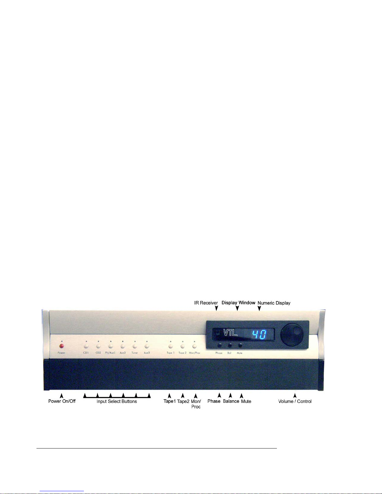
TL 6.5 Front Panel Controls
From the front panel of the unit you can access all of the controls and program all the
functions of the preamplifier, as well as from the rear-mounted RS-232 port
Fig. 1 Front Panel
TL6.5 Preamplifier Owner’s Manual
VTL
8

You can operate the various controls and buttons from the front panel to access the full
functionality of this unit, and the operational functionality can also be accessed via the
remote control. The indication LEDs show the various operating modes of the unit.
1. The Power button is used to turn the preamplifier on and off. If the unit is powered off
press the button to turn the preamplifier ON and press the switch down again to turn
the unit OFF. The Power LED will blink blue during warmup, remain on steady blue
after power up, and turn off during power off or standby.
2. The Input Select buttons are used to select the source component for the preamplifier.
You can choose any one of the six inputs by pressing the appropriate selector button
labeled with the selection of your choice. The 6 input selector switches are divided up
into two groups: The first three from left to right can be configured as either balanced
or single ended inputs, and during power up the first two buttons double as trigger
programming buttons (when not in locked mode).
The first two LEDs are red for trigger functions, and the first three can be set blue for
balanced setting and green for single ended setting.
The other two buttons on the right of the first group are single ended inputs only, and
are not used for any other function. The LED color is green.
Warning It is critical for proper sonic performance of this
component that it be properly configured for the mode of
operation while playing. If a balanced signal is applied to the
inputs the unit must
be configured for balanced operation, and vice-versa.
3. The Tape 1 and Tape 2 inputs are also usable as normal (single ended only) inputs, with
the additional capability of handling the record out function. LED color is green for
input, and red for monitor.
4. The Mon/Proc button is used to monitor an output when recording to one of the Tape
inputs, and is also used to set a Unity gain input (when not in locked mode.) The LED
color is red during monitor.
The Mon/Proc can be used to select whether the signal at the preamplifier output is
coming from tape monitor or not. If you wish to use the preamplifier to monitor an
ongoing recording session from the tape deck, you can use the Mon/Proc button to set
the preamplifier to Tape Monitor mode.
The Mon/Proc button is also used to set any input for unity gain (when not in locked
mode). This function
is used for routing an external surround processor to the front left
and right channels. In this mode, your external surround processor will control the levels of
all of the channels of your system, including the front left and right channels. In this mode
the preamplifier is in the unity gain mode, and the volume control is set to a fixed position
(equivalent to volume position 69 in single ended mode). The signal is passed to the front
left and right amplifiers through the gain stage of the preamplifier, but at the same volume
as the surround processor is putting out, and the preamplifier’s volume control is disabled.
5. The display window contains the group of three main operational buttons and display
LEDs, the numeric display, and the infra red remote receiver, which enables the
TL6.5 Preamplifier Owner’s Manual
VTL
9

transmission of signal from the remote hand-held unit to be received by the
preamplifier. Keep this window clear from any obstruction and out of direct light to
allow maximum signal transmission from the remote wand.
The three main operational buttons are:-
a) The Phase button allows you to switch the system into the phase reversed state.
• Clicking the Phase button toggles the system between the phase correct and
phase inverted states. The Phase LED will turn off when the system is in
phase correct state, and will be red in the phase-inverted state.
b) The Balance button allows the user to change the channel balance setting between
left and right channel.
• Holding down the Balance button changes the display to the balance display
and sets the Balance LED to blue. Rotating the rotary knob changes balance
from left to right, according to the direction of rotation. In this mode the
control knob is used to set the left and right channel level.
In the Balance mode, when the display shows a double dash this indicates that
the left and right channels are equally balanced. A number with a bar on either
side indicates an out of balance setting, with the bar indicating the direction of
balance and the display indicating the degree of out of balance.
The display automatically reverts to volume readout a few seconds after
release of the Balance button.
c) The Mute button is to allow you to switch the preamplifier into the muted state.
• Pressing the button toggles the system between the mute and operating state.
If the preamplifier is currently in the operating state, pressing the Mute button
will set the unit to the muted state, indicated by a red flashing Mute LED. If
the preamplifier is currently in mute state, pressing the Mute button will
change the system into the operating state, and the LED will turn off.
The Numeric display is used to indicate either the sequential countdown timer during
power-up, offset level of the selected input, channel balance offset, trigger timing
during trigger output programming (during power up only), and the overall volume
gain level setting.
6. The Control knob is used in conjunction with the Numeric Display for setting volume
gain level in the operate mode, or when in one of the programming modes (trigger
programming, channel balance setting or input offset programming mode) the control
knob is used to dial in the appropriate setting.
• When in volume control mode the control knob changes the loudness level
of the output from your speaker system. Turning the knob clockwise
increases the volume level, and turning the knob counter-clockwise decrease s
the volume level.
TL6.5 Preamplifier Owner’s Manual
VTL
10
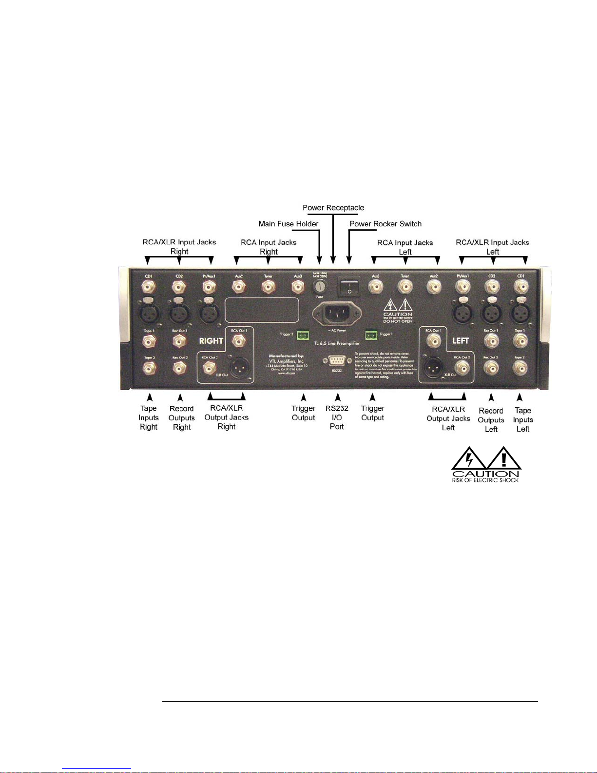
The Preamplifier’ s Back Panel
From the back panel of the chassis you can access the power connector, trigger outputs,
RS-232 port, AC fuse, and the serial number and power consumption of the unit, as well
as all of the audio inputs and outputs.
Fig. 2 Rear Panel
Back Panel Connections and controls
The Power Receptacle is used for connecting the TL 6.5 to the AC power from a wall outlet
using the power cord.
The Main Fuse Holder contains the main power fuse. CAUTION:
Replace fuses only with fuses of same type and rating.
The Power Rocker powers the unit into standby mode. Press up for on and down for off.
The Trigger Outputs provide a 12V DC signal to external components that are to remotely
power up after the preamplifier is operational. Connect the power amplifiers’ trigger inputs
to the TL 6.5’s Trigger Outputs to remotely power the amplifier(s) on and off.
The Information label contains Serial number, AC voltage setting and power consumption
information.
The RCA and XLR Input Jacks.
3 pairs of single-ended/balanced line inputs to connect source components to the
preamplifier section of the TL 6.5, including CD, DVD/SACD, and Phono/Aux 1
3 single-ended RCA inputs Aux 2, and Tuner and Aux 3
2 pairs of single ended RCA Tape inputs
The RCA and XLR Output Jacks.
TL6.5 Preamplifier Owner’s Manual
VTL
11
2 pairs single ended and 1 pair balanced Main Outputs
2 pairs of fixed single ended buffered record outs
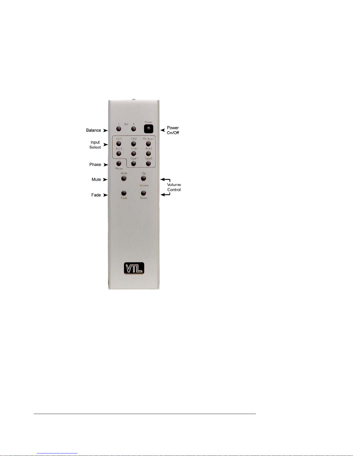
The Remote Control Hand-held Unit
Fig 3. Remote Control Unit
The Remote Control hand held unit supplied with this preamplifier allows the user to
perform the following functions:
• Power the preamplifier on and off. This is a toggle control, which changes the
state from one to the other each time it is pressed.
• Set the left and right channel balance offset
• Select any of the 8 inputs directly
TL6.5 Preamplifier Owner’s Manual
VTL
12
 Loading...