

VTL TL5.5 Owner's Manual

MaftnAtubes
usey-fiirnbb
HANDtrRAFTED IN THE UAA
VTL
TL5.5 Line
Stage
Preamplifier
IxrnoDI]CTION
I
Electrical
Safety
l{otice
1
Water and
Moisture
.
1
Location and
Ventilation
Servicing
Gr,ruNG SranrE,D
3
TL
5.5
Front Panel
Controls
.'
Inverted phase and
The Preamplffier's Back Panel
j
The Remote
Control
Hand-held
Unit
6
Fitting
the
Batteries
to the
Remote
Control
7
Connecting
Your Preamplifier to
your
system
8
Powering
your
system on
.. .
.... e
Using the
Preampltfier with
the
Remote
Control
e
Powering
the system ,ff
io
CI{APTER3
........ 1l
OpT,naTING
THE PREAMPLIFIE,R
II
Connecting and Selecting Source Components
t t
Power
On Stages
tl
Connecfing
the TL5.5 to a Home
Theater
5ystem.........
.......... I l
Using the Tape
Loop
to monitol recordtngs..
..... 12
Connectrnga second
pair
of
amp1ifers................
.................. 1-l
TL5.5
Prcamplifier
Owney's
tanual
VTL
Cang AND
Man.TTENANCE
OF
YOUR VTL
PREAMPLIFIER
17
Bngar IN PpruoD ,7
Changing
Tubes t8
Changing
the Main Fuse 20
Troubleshooting
2l
SpEcIFICATIONS 23
WannaNTY 24
WarranQ Registration
26
Serttic
TL5.5
Preamplifier
(lwneds
tanual
VTL
ii
CHAPTER
1
Itrtrot[rction
Congratulations nn-yzurpurchase
of a
VTLPure
tube
preamplfin
his hand
crafted equrpment is
designed
to deliver superb performance
for
your
listening
pleasure
for
marry
years
to
come.
Please
take a
moment
to
read
through
this ownels
manual. You
wdl
get an
idea
of the
installatron
procedures
needed
to
connect
this preamplifier
to the
rest
oi
vour
audio
system,
as
well
as
the various
functions
this preamplifier
can
perform. Please
take enough trme to
get
familiar
with the
features
of this
product.
After
you
have finished
reading
this
manual
please
keep it in
a sat-e
place
for
future
reference.
The
VTL
tearn
is
proud
that you
have
selected our pure tube preamplifier as a new
member
of
your
home
audio system. This
preamplifier
is
designed
to
gve
you the
convenience and
flexibility
to manage
all
your
audio
and
r,rdeo
sources, while at
the
sarne
nme givrrg you
the
musical
experience
that
is
the
most
alive and the truest to your source.
We
hope
you'll get
many hours
of enioyment from it,
Elec{rhal
SaffiV
Ndbe
Electncal
voltage from
power
cables
is hazardous.
We recoffrnend
that the power cord
connected
to this
unit be used with
a propedy grounded
oudet.
To
prevent
electncal
shock, do
not remove
the cover
of this
preamplifier while
the unit
is
powered
on.
Prior
to
connecting
this preamplifier to
ar-ry audio
or
video
equipment
in
your
system,
make
sure
this unit's
power
(and
the rest
of the equipment
connected to
its input
and
ouput
channels)
is
tumed off Adding
or
removing
input
or ouput
cables to the
preamplifierwhile
the system
is
powered
on
can cause
d*up
to the system.
Waterand
lllbisnure
The
preamplifier should
be used
N^y
from
water
or
moisture. If liqurd
enters the
preamplifier it must
be
immediately
returmed
to
your dealer
for
servrcing.
In
this
case
you
should under no
circumstances
try to power
the unit on
-
there zre
hazardous
voltages
present in
this unit that can
cause serious
iri,rry
if
they come
in
contact
with
you.
Location
and
\tentiHion
Install
this preamplifier in a location
that
is
stable urd well ventilated. If
the preamplifier is
placed
h
a built-in
installation,
ensure
that there
is
adequate
room for
a supply
of air to
flow
throug!
the ventilation
openin5.
Allow
at
least
3
-
5
inches
clearance on the
top and
TL5,5 Prcamplifier
OwncCs
Hanual
I
VTL
aroLuld the sides of the preamplifier.
Be
sure the
preamplifier
is
at
least
10
inches
away
from
your amplifier
to prevent possible
noise rntroduction rnto
your system.
Tiptoes
or
other
isolation
accessories
may
prove useful in
reducing mechanical
vibratrons.
Do not
place the preamplifier
next
to
heat
soLrrces such as
radiators, stoves
or other appliarrces.
Do
not
place the preamplifier
on
the
floor where small
children can tamper
wrth
the
equipment.
If it is not
possible
to place the preamplifier out of the
reach
of small children
it is recommended
that
you
remove
power cables when the eqtupment
is not in
use.
Servbittg
Do not
attempt
to service
the
preamplifier
beyond the
procedures
described
in
ttus
marrual. For
all other service and questions, please contact
your
authorized \TL dealer or
the
factory.
TL5.5 Prempllfier
Owney'c
Hanual
VTL
2
CHAPTER 2
Gettingffi
After
you open the carton you should
find
the
following
items inside:
.
The
preamplifier,
with a power cord
.
The remote
control
hand-held unit with trvo
AAA
batteries
o
This
Owner's
Manual, VTL
Qualitv
Assurance test document,
VTL
product warrans.
regstration
card
Remove
each
item from its
pack4ging
material and check to
make
sure
that
no
phvsicai
dam4ge
has
occurred during shipping of the unit.
There
should
be
no
rattles inside
either
oi the
preamplifier
or
remote control uruts.
took
througfr the
vent slots and check to see
that the tr"rbes
^pper properly seated
firmly
n their sockets. Contact
your
VTL dealer
immedrately if
physical damage
is detected.
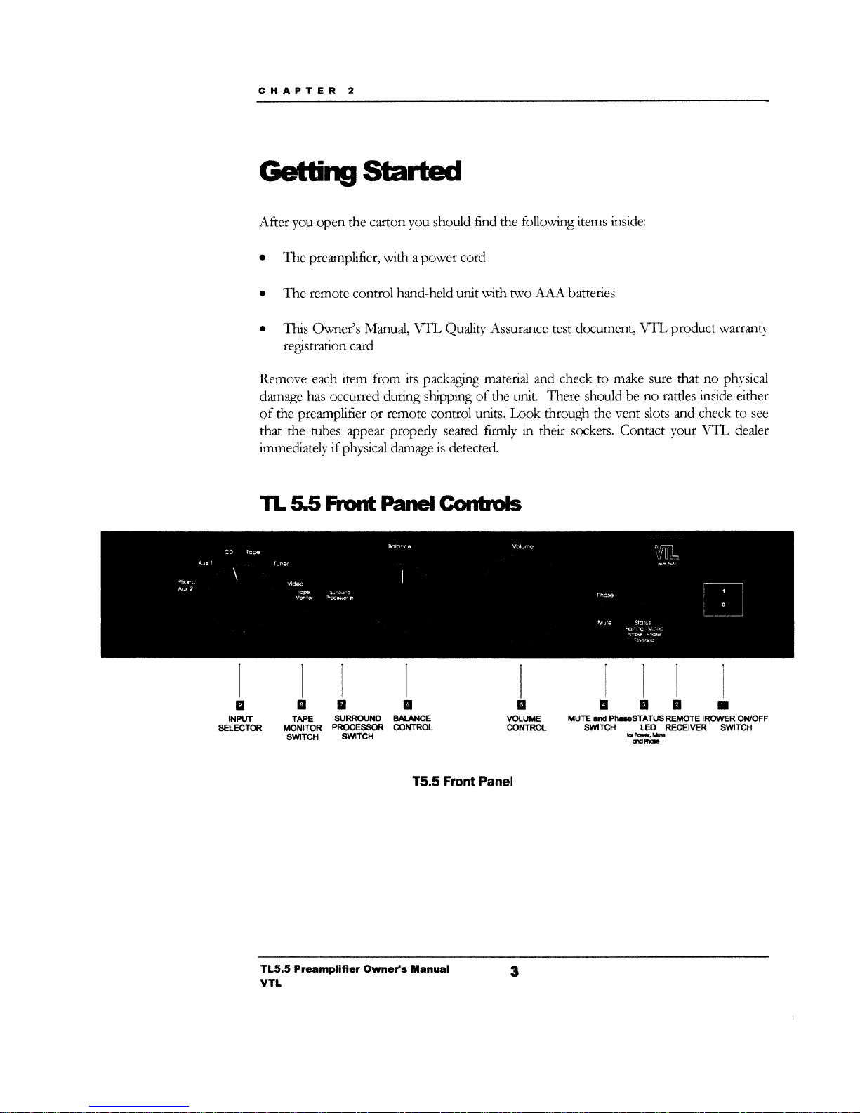
TLSS
front
Panel
Gonhls
E
VOLUME
CONTROT
E
INPUT
SELECTOR
qE
TAPE
SURRC'UND
INN|TOR
PROCESSOR
swlTcH
swlTcH
u
EAI.ANCE
@NTROL
EEEII
MUTE
STd PhS€STATTJSREIiOTE IRO1IYER ON/OFF
SWITCH
LED
RECEIVER SWITCH
frdhlr,trLlb
ANFE
T5.5 Front Panel
TL5.5 Prempllftcr Owncy's
tanual
VTL
3
You
can operate
the
various
controls and
switches
from
the
front
panel
to
access the full
functronaliw of the urut.
The
status
indrcation
I.trD
shorvs the various operating
modes
of
the urut.
l. The Pouvr
On/Of xvitch can be
used
to turn the preamplifier
on
and off.
Press
the
svzitch up to tum the preamplifier ON and press the switch down to tum the
r-nit
OFF.
Tlne
Status
LED
should be on
and off
respectively,
accordrng to
the
setting of
the
Poaer
Oa switch.
Galk
about
flashing LED)
2.
The
Renote
Rereiw window
allorvs the transmission of srgnal
from
the
remote hand-
heid
unit
to be
received
by the preamplifier.
Keep
tkus
window
clear
from
any
obstruction to allow
maximum
srgnal
transmission.
3.
The
Status
LED indicates
the
operating mode
of the
preamplifier. The modes
are:
Pwerqr ildoft
o
\X{ren
the
unit
is
powered
on, the
LED
light
will be
lit.
W}ren
the unit
is
powered off the
LED lght is
ott.
tub
ild openatirlg:
.
When
the unit
is in mute
the
LtrD hgfrt
is
blinkrng. When the r-urit
is
in
normal
operaung
mode,
the LED hght will
stay
lit
constandy.
Inrertcd
plmcand
nqr.fowerted
phGe
.
When
the unit
is
operatrng
out of phase, the
LED
vill
change to amber color.
If
the phase
is
normal,
then the
LEI)'s
color
is
green.
4.
The
Phase/Mutc
switch
is
a
momentary
togle
swrtch to allow
you to
switch the svstem
into
the mute
state or the phase reversed
state.
.
If
the preamplifier
is
currently in
the operabng state
-
press the switch down.
The
preamplifier
will
go
into
rnute
state as
indrcated
by the
flashing
Status
LtrD. If
the preamplifier is
currently
in
mute
state, clicking this switch
down
^g
tnwill
change the system
back
mto
the operating
state. Clicking the switch
in
the downward position
togles the system between
the
mute
and operating
state.
.
Clicking the switch
upward toggles the system
between the phase
reversed
and
phase normal
state.
Tl;.e
Status
LED
will
tum amber when the
system
is
in
pha^se reversed
state.
5.
The
Volume
Control
knob
changes
the
loudness
level of
the output
from
your
speaker
system. Tumrng
the knob
clockwise will
urcrease
the
volume level. Alternatively,
tuming the
knob
counter-clockwise will
decrease the
volume level.
6.
The
Sunuund
Pmnssor This
switch can be used
to change the
control of your
audro/video
system to the surround processor when
the swrtch
is
tumed to the
Prccessor Ia
position.
In
this
mode,
the surround system will
only control
all
of the
Tt5.5
Preampllfier Owney's Hanual
4
VTL
channels
oi your
systerrq
and
the preamplifier
is rn the unity
gain
mode.
In
thrs
mode
the
volume control
and the
amplificauon
stages
of
the
TL5.5
are blpassed
completely,
and
the signal
is
passed
to the
front
left
and
nght
amplifien
at precisely
the same
volume as
the surround
processor
is
putting
out.
In
the
default operaflng
mode
oi the preamp,
the Pranssor
switch
stays
n
the
down posinon.
Tkus means
that
the
preamplifierwill
not
be
receir,'ing
the
srgnal
from
the
surround processor.
The Tqe Morutor can be
used to
select v'hether the
input
source
is
coming
from
tape
monitor or
not.
If
you
wish to use the preamplifier
to
monitor an ongomg
recording
session
from
the tape
decb you can
select this
switch to
Tape
Monitor
mode. In
this
state the
plavback
from the preamplifier
will come directly
from the tape deck.
The
unit
is shipped
in
the
default-operatmg
mode
of the
preamp
with the swrtch
in
the
dorvn positron.
This means that the
input source
will
not
come
from
the
tape
deck,
but will be dependent
on the
nput
selection
made
on the
preamplifier.
The Balann Conhvl
knob
can be used
to set the
left
and
riglrt
channel
level. \X4een the
line
on the
knob is rn
the
12
o'clock
position
this
indrcates that the
left
and
nght
channels are equally
balanced.
\'ou
wrll
feel
a center
dent
in
the control
to
indicate
tlrrs
exact positron.
The Input
Sehctor
can be used to select
the source
component
for
the
preamplifier.
You
can
choose any one of
the six
inputs
bv tuming
the selector
knob
to
the
location
as
marked
above the
knob.
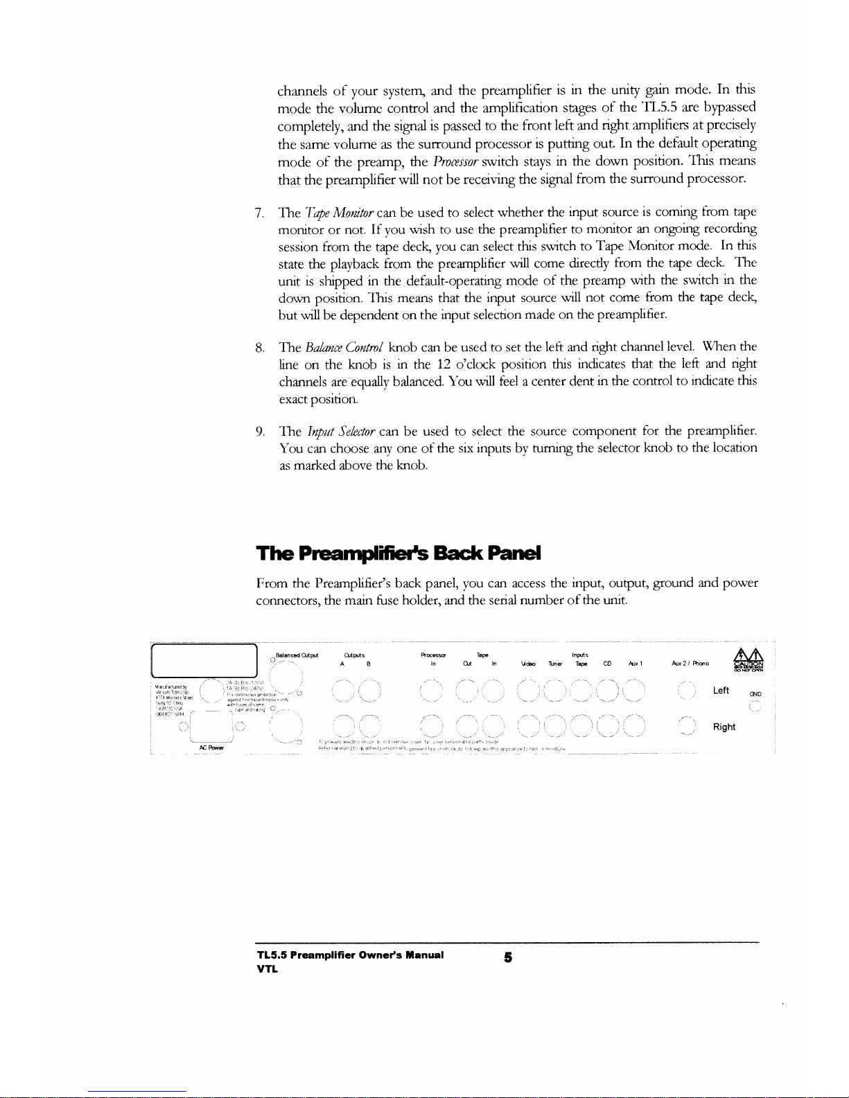
The Prcamifieils
Bact( Panel
From the
Preamplifier's
back panel, you can
access the
input,
output,
ground and power
connectors,
the
main
fuse
holder,
and
the serial
number
of
the unit.
8.
9.
M
Ptcs
Tapa
ln OJi
In
Intrns
Vd€o
Tuns Tape CD Arx
1 Arx 2 / Phso
CND
Right
TL5.5 Preamplifier Owneds
tanual
vTt
5
 Loading...